Geokon 6160 User manual

No part of this instruction manual may be reproduced, by any means, without the written consent of Geokon®.
The information contained herein is believed to be accurate and reliable. However, Geokon®assumes no responsibility for errors,
omissions or misinterpretation. The information herein is subject to change without notification.
Copyright © 2006-2019 by Geokon®
(Doc Rev T, 05/01/2019)
Installation Manual
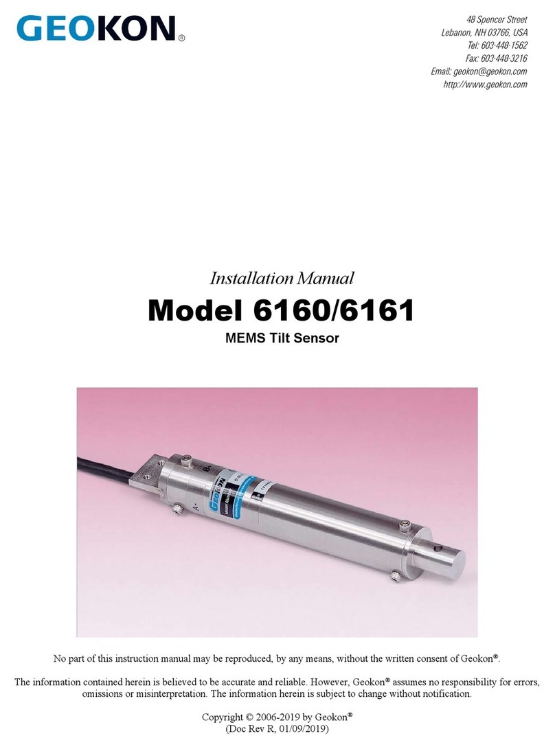
Model 6160/6161
MEMS Tilt Sensor


Warranty Statement
Geokon warrants its products to be free of defects in materials and workmanship, under normal
use and service for a period of 13 months from date of purchase. If the unit should malfunction,
it must be returned to the factory for evaluation, freight prepaid. Upon examination by Geokon,
if the unit is found to be defective, it will be repaired or replaced at no charge. However, the
WARRANTY is VOID if the unit shows evidence of having been tampered with or shows
evidence of being damaged as a result of excessive corrosion or current, heat, moisture or
vibration, improper specification, misapplication, misuse or other operating conditions outside of
Geokon's control. Components which wear or which are damaged by misuse are not warranted.
This includes fuses and batteries.
Geokon manufactures scientific instruments whose misuse is potentially dangerous. The
instruments are intended to be installed and used only by qualified personnel. There are no
warranties except as stated herein. There are no other warranties, expressed or implied, including
but not limited to the implied warranties of merchantability and of fitness for a particular
purpose. Geokon is not responsible for any damages or losses caused to other equipment,
whether direct, indirect, incidental, special or consequential which the purchaser may experience
as a result of the installation or use of the product. The buyer's sole remedy for any breach of this
agreement by Geokon or any breach of any warranty by Geokon shall not exceed the purchase
price paid by the purchaser to Geokon for the unit or units, or equipment directly affected by
such breach. Under no circumstances will Geokon reimburse the claimant for loss incurred in
removing and/or reinstalling equipment.
Every precaution for accuracy has been taken in the preparation of manuals and/or software,
however, Geokon neither assumes responsibility for any omissions or errors that may appear nor
assumes liability for any damages or losses that result from the use of the products in accordance
with the information contained in the manual or software.


TABLE of CONTENTS
1. INTRODUCTION ...................................................................................................................................................1
2. INSTALLATION ....................................................................................................................................................3
2.1 PRELIMINARY TESTS............................................................................................................................................3
2.2 INSTALLING MODEL 6160 SENSORS ....................................................................................................................3
2.2.1 Mounting Brackets ......................................................................................................................................3
2.2.2 Mounting the Sensor ...................................................................................................................................6
2.2.3 Sensor Protection........................................................................................................................................7
2.3 INSTALLING MODEL 6161 SENSORS ....................................................................................................................7
2.3.1 A Axis Tilt Adjustments ...............................................................................................................................8
2.3.2 B Axis Tilt Adjustments ...............................................................................................................................8
2.4 JUNCTION BOXES.................................................................................................................................................9
2.5 SPLICING..............................................................................................................................................................9
3. TAKING READINGS...........................................................................................................................................10
3.1 DATALOGGERS ..................................................................................................................................................10
3.2 RB-500 READOUT BOX .....................................................................................................................................10
3.3 MEASURING TEMPERATURE ..............................................................................................................................10
4. DATA REDUCTION ............................................................................................................................................11
4.1 TILT CALCULATION ...........................................................................................................................................11
4.2 TEMPERATURE CORRECTION .............................................................................................................................11
4.3 ENVIRONMENTAL FACTORS...............................................................................................................................11
5. TROUBLESHOOTING........................................................................................................................................12
APPENDIX A. SPECIFICATIONS.........................................................................................................................13
A.1 MEMS TILT SENSOR ........................................................................................................................................13
A.2 THERMISTOR.....................................................................................................................................................13
APPENDIX B. THERMISTOR TEMPERATURE DERIVATION...... ERROR! BOOKMARK NOT DEFINED.
APPENDIX C. SAMPLE CALIBRATION REPORT ...........................................................................................14
APPENDIX D. WIRING CODES ............................................................................................................................16
APPENDIX E. 6160 STANDARD ADDRESSABLE SYSTEMS..........................................................................17
APPENDIX F. PROGRAMMING THE MEMS TILTMETER WITH CRBASIC ............................................19
APPENDIX G. PROGRAMMING THE ADDRESSABLE MEMS TILTMETER WITH CRBASIC.............20

FIGURES
FIGURE 1-MODEL 6160 MEMS TILT SENSOR.............................................................................................................. 1
FIGURE 2-MOUNTING BRACKET FOR THE MODEL 6160 TILT SENSOR ......................................................................... 1
FIGURE 3-MODEL 6161A TILT SENSOR (VERTICAL ORIENTATION,BIAXIAL MODEL SHOWN)..................................... 2
FIGURE 4-MODEL 6161B TILT SENSOR (VERTICAL ORIENTATION,BIAXIAL MODEL SHOWN) ..................................... 2
FIGURE 5-TILTMETER MOUNTING BRACKETS.............................................................................................................. 3
FIGURE 6-DROP-IN ANCHOR INSTALLATION ................................................................................................................ 4
FIGURE 7-ANCHOR ROD .............................................................................................................................................. 5
FIGURE 8-UNIAXIAL OR BIAXIAL TILTMETER INSTALLATION DETAILS ....................................................................... 6
FIGURE 9-ADJUSTMENT SCREW LOCATIONS................................................................................................................ 8
FIGURE 10 -SAMPLE MODEL 6160 CALIBRATION REPORT...........................................................................................15
TABLES
TABLE 1-MODEL 6160 AND 6161 TILT SENSOR SPECIFICATIONS................................................................................13
TABLE 2-THERMISTOR RESISTANCE VERSUS TEMPERATURE...............................ERROR!BOOKMARK NOT DEFINED.
TABLE 3-CABLE 03-250V0 WIRING............................................................................................................................16
TABLE 4-ADDRESSABLE MEMS (LOGIC LEVEL STYLE)WIRING ...............................................................................17
TABLE 5-THERMISTOR BRIDGE CIRCUIT.....................................................................................................................18
EQUATIONS
EQUATION 1-INCLINATION VERSUS VOLTS ................................................................................................................11
EQUATION 2-TILT VERSUS VOLTS ..............................................................................................................................11
EQUATION 3-TILT VERSUS VOLTS CORRECTED FOR TEMPERATURE ..........................................................................11
EQUATION 4-CONVERT THERMISTOR RESISTANCE TO TEMPERATURE .................ERROR!BOOKMARK NOT DEFINED.

1
1. INTRODUCTION
The Geokon Model 6160 MEMS Tilt Sensor is designed for permanent long-term monitoring of
changes in tilt of structures such as dams, embankments, foundation walls, retaining walls,
buildings, and the like. There are two main types of Tilt Sensors: The Model 6160 is an adaption
of the tiltmeter used in Model 6150 In-Place Inclinometer, and the 6161 utilizes the same MEMS
sensors inside a Nema 4 enclosure. Examples of each type are shown in the Figures below. Each
style of housing contains either one or two Micro-Electro-Mechanical Systems (MEMS) sensors
oriented at 90 degrees to measure biaxial tilts. All types include a thermistor for measuring
temperatures.
They are designed to be attached to the structure so that they can sense and measure any tilting of
the structure in uniaxial or biaxial directions. Angular changes of as little as two arc seconds can
be detected.
Figure 1 - Model 6160 MEMS Tilt Sensor
Figure 2 - Mounting Bracket for the Model 6160 Tilt Sensor

2
Figure 3 - Model 6161A Tilt Sensor (Vertical Orientation, Biaxial model shown)
Figure 4 - Model 6161B Tilt Sensor (Vertical Orientation, Biaxial model shown)

3
2. INSTALLATION
2.1 Preliminary Tests
Prior to installation, the sensors need to be checked for proper operation. Each tilt sensor is
supplied with a calibration report, which shows the relationship between output voltage and
inclination. The tilt sensor electrical leads are connected to a Datalogger or the RB-500 readout
box (see Section 3 for readout instructions) Hold the sensor in an approximately vertical position
and observe the reading. The sensor must be held in a steady position. The current reading
should be close to the factory vertical reading provided on the calibration report. (See Appendix
C. for a sample calibration report.) The temperature indicated by the thermistor should be close
to the ambient temperature.
Checks of electrical continuity can also be made using an ohmmeter. Resistance between any
conductor and the shield or the case should exceed two megohms.
2.2 Installing Model 6160 Sensors
2.2.1 Mounting Brackets
The first step is to install the uniaxial/biaxial mounting bracket (Figure 5), which is
designed for mounting on vertical walls. The bracket may be mounted using a drop-in
anchor or an anchor rod that is epoxied or grouted in place. See Section 2.2.1 for
instructions using drop-in anchors, and Section 2.2.2 for anchor rods.
Figure 5 - Tiltmeter Mounting Brackets

4
2.2.1.1 Mounting with a Drop-in Anchor
1) Mark the location where the bracket will be installed.
2) Using a hammer drill, drill a 12 mm (0.5") hole approximately 37 mm (1.5") deep.
Clean the hole thoroughly, blowing out with compressed air if possible.
3) Insert the 3/8" drop-in anchor with setting pin into the hole. The threaded end should
be closest to the opening.
4) Insert the provided setting tool, small end first, into the anchor. Expand the anchor by
hitting the large end of the setting tool with several sharp hammer blows.
5) Thread the supplied 3/8-16 anchor rod into the anchor.
6) Attach the mounting bracket to the bolt using the supplied hardware, as illustrated in
Figure 6.
7) Use a leveling device to align the bracket vertically to the wall.
Figure 6 - Drop-in Anchor Installation
Top
View
Tilt A
_
+
Flat Washer
2" 3/8
-
16 Anchor Rod
Flat Washers
Lock Washer
3/8
-
16 Nuts
Wall
3/8" Drop
-
In Anchor
Setting Pin
Tilt B
+
_
10-32 Nuts
10-32 Cap Screws

5
2.2.1.2 Mounting with an Anchor Rod
1) Mark the location where the bracket will be installed.
2) Using a hammer drill, drill a 12 mm (0.5") hole approximately 100 mm (4") deep.
3) Clean the hole thoroughly, blowing out with compressed air if possible.
4) Mix the grout or epoxy and fill the hole.
5) Push the 1/2-13 threaded anchor rod into the hole. (Use a hammer if necessary to get
the anchor to reach the bottom.)
6) Let the anchor rod set before continuing the installation.
7) After setting, attach the mounting bracket to the bolt using the supplied hardware as
illustrated in Figure 7.
8) Use a bubble level or other leveling device to align the bracket vertically to the wall.
Figure 7 - Anchor Rod
Top View
Flat Washer
4" 1/2-13 Anchor Rod
Epoxy or Grout
Flats to Prevent Bolt Twisting
Flat Washers
Lock Washer
1/2-13 Nuts
Wall

6
2.2.2 Mounting the Sensor
1) Attach the tiltmeter to the mounting bracket using the supplied 10-32 cap screws,
washers, and nuts. The cap screws should be installed finger-tight at this time.
2) Attach a portable readout such as the RB-500 to the tiltmeter and observe the reading.
(See Section 3 for readout instructions.)
3) Adjust the sensor in the slot of the mounting bracket while observing the readout until
the tiltmeter reads within ±0.15 volts of the zero reading shown on the calibration
report supplied with the sensor. (See Appendix C for a sample calibration report.)
4) Tighten the cap screws to secure the tiltmeter in place.
5) Check the reading again after tightening to make sure it still reads within ±0.15 volts
of the zero reading. Figure 8 shows the completed installation.
For biaxial sensors: Perform the steps above with the A axis reading. The positive
direction of the B axis is 90° clockwise from the positive direction of the A axis. (When
looking downwards in plan. See Figure 8 below.) Adjustment of the B axis is as follows:
1) Loosen the 3/8-16 nut on the mounting bracket.
2) Adjust the sensor position by rotating the bracket while observing the readout of the B
axis until the tiltmeter reads within ±0.15 volts of the zero reading shown on the
calibration report supplied with the sensor.
3) Tighten the nut to secure the mounting bracket in place.
4) Check the reading again after tightening to make sure it still reads within ±0.15 volts
of the zero reading. Figure 8 shows the completed installation.
Figure 8 - Uniaxial or Biaxial Tiltmeter Installation Details
Top View
Tilt A
-
+
Instrument Cable
(Four conductor, 22 AWG)
10-32 Cap Screws
10-32 Nuts
Wall
Mounting Bracket
Tilt B
(Biaxial sensors
only)
-
+

7
2.2.3 Sensor Protection
If the tiltmeter is installed in an exposed location where damage due to vandalism,
construction, or other factors might occur, it should be covered with a protective
enclosure and/or insulation.
For best results, the tiltmeter should be shielded from direct sunlight.
2.3 Installing Model 6161 Sensors
1) Place the tiltmeter on the mounting surface.
2) Align the tiltmeter so that the A axis (and B axis if applicable) is aligned with the direction of
the expected tilt.
3) Use the holes in the tiltmeter mounting plate to mark where the drop-in anchors will be
installed.
4) Using a hammer drill, drill four 9.5 mm (3/8”) diameter holes approximately 32 mm (1.25")
deep. Clean the holes thoroughly, blowing out with compressed air if possible.
5) Insert the four 1/4" drop-in anchors with setting pin into the hole. The threaded end should be
closest to the opening.
6) Insert the provided setting tool, small end first, into the anchor. Expand the anchor by hitting
the large end of the setting tool with several sharp hammer blows.
7) Thread the supplied 1/4-20 threaded anchor rods into the anchors.
8) Slide the tiltmeter over the anchor rods until it is flush with the mounting surface.
9) Thread the 1/4-20 nuts onto the anchor rods until they are finger tight.
10) Attach a portable readout such as the RB-500 (see Section 3 for readout instructions) to the
tiltmeter and observe the reading of the A axis (and B axis if applicable).
11) If the readings are not within ±0.15 volts of the zero reading shown on the calibration
report supplied with the tiltmeter, follow the instruction in Section 2.3.1 and 2.3.2 to adjust the
position of the MEMS sensor(s). If the readings are within ±0.15 volts of the zero reading shown
on the calibration report, tighten the 1/4-20 nuts to secure the tiltmeter in place. Check the
reading again after tightening to make sure it still reads within ±0.15 volts of the zero reading.
(A sample calibration report is shown in Appendix C.)

8
2.3.1 A Axis Tilt Adjustments
1) Use a Phillips head screwdriver to loosen the A axis adjustment screw (refer to Figure
9 below).
2) Adjust the position of the sensor mounting bracket until the A axis of the tiltmeter
reads within ±0.15 volts of the zero reading shown on the calibration report supplied
with the sensor. (See Appendix C for a sample calibration report.)
2.3.2 B Axis Tilt Adjustments
1) Open the tiltmeter by unscrewing the four captive screws on the front of the
enclosure. Make sure that no dirt, water or other contaminants are allowed to
enter the enclosure.
2) Use the Allen wrench provided to loosen the B axis adjustment screw (see Figure 9).
(Note that on tiltmeters configured for horizontal orientation the B axis adjustment
screw is located underneath the sensor mounting bracket.)
3) Adjust the position of the sensor mounting bracket until the B axis of the tiltmeter
reads within ±0.15 volts of the zero reading shown on the calibration report supplied
with the sensor. (See Appendix C for a sample calibration report.)
4) Make sure the gasket on the underside of the cover is clean and properly seated inside
the groove.
5) Place the cover on the unit.
6) Tighten the cover screws a little at a time, working in a diagonal pattern, making sure
the cover closes and tightly and evenly
Figure 9 - Adjustment Screw Locations

9
2.4 Junction Boxes
For manual readout with an RB-500 readout box, cables from the individual sensors are
connected to a switchbox. If a Datalogger is used the cables are connected directly to the
Multiplexer. In both cases, the wiring code shown in Appendix D is used.
2.5 Splicing
The cable used for making splices should be a high-quality twisted pair type with 100%
shielding (with integral shield drain wire). When splicing, it is very important that the shield
drain wires be spliced together. Splice kits recommended by Geokon incorporate casts placed
around the splice then filled with epoxy to waterproof the connections. When properly made, this
type of splice is equal or superior to the cable in strength and electrical properties. Contact
Geokon for splicing materials and additional cable splicing instructions.

10
3. TAKING READINGS
3.1 Dataloggers
In most cases the 6160 and 6161 MEMS Tiltmeters will be monitored continuously and
automatically using a Datalogger. Connector pin designations for the various tiltmeter models
are shown in Appendix D.
3.2 RB-500 Readout Box
The RB-500 readout box is designed to take readings for manually transcribing into a field book;
it has no storage capabilities. This method is useful for reading systems that do not require
continuous monitoring. The RB-500 readout box is also useful during initial installations and for
setting up Datalogger systems. Connections to RB-500 are delineated on the readout.
3.3 Measuring Temperature
Although the temperature dependence of the MEMS tiltmeter is very small, the structure being
monitored is usually affected by temperature to some degree; therefore, the gauge temperature
should always be recorded, and efforts should be made to obtain readings when the instrument
and structure are at thermal equilibrium. The best time for this tends to be in the late evening or
early morning hours. (In landslide applications where the MEMS sensors are buried in the
ground, temperature variations are very small or nonexistent and ground movements are
unaffected by temperatures. In these situations, it is not necessary to measure temperatures.)
An important point to note is that sudden changes in temperature will cause both the structure
and the Tiltmeter to undergo transitory physical changes, which will show up in the readings. For
best results, the tiltmeter should be shielded from direct sunlight.
Each MEMS tilt sensor is equipped with a thermistor for reading temperature. This enables
temperature-induced changes in tilt to be distinguished from tilts due to other sources. Section
4.2 provides an equation to correct the readout of the sensor for temperature.
Please note that Geokon model RB-500 cannot read temperatures; a separate digital ohmmeter is
required. To read the temperature using an ohmmeter, connect the ohmmeter to the two
thermistor leads of the tilt sensor. Use Appendix B to convert the measured resistance to
temperature. (Since the resistance changes with temperature are so large, the effect of cable
resistance is usually insignificant. For long cables a correction can be applied, equal to
approximately 14.7 Ω per one thousand feet [48.5Ω per km] of 22 AWG stranded copper leads.
Multiply this factor by two to account for both directions.)

11
4. DATA REDUCTION
4.1 Tilt Calculation
The output of the MEMS Sensor is proportional to the sine of the angle of inclination from the
vertical. For the ±15-degree sensor the FS output is approximately ±4 volts. The reading (R) in
volts displayed on the RB-500 readout box, and the inclination (θ) is given by the equation:
θ=(R1-Rzero) G degrees
Equation 1 - Inclination Versus Volts
Where;
Ris the current reading in volts
Rzero is the reading at θ=zero
G is the Gauge Factor shown on the calibration report for the Model 6160 tiltmeter.
For measurements of tilt, i.e., changes of inclination, where R0 is the initial reading and R1 is a
subsequent reading, the small zero reading, Rzero at zero inclination cancels out so that:
Calculated Tilt = G(R1-R0)
Equation 2 - Tilt Versus Volts
4.2 Temperature Correction
The Model 6160 MEMS Tiltmeter has very small temperature sensitivity equal to +1 arc second
per degree centigrade rise. The tilt corrected for temperature is:
Tilt = G(R1corr – R0) degrees
Equation 3 - Tilt Versus Volts Corrected for Temperature
Where;
R1corr = R1– 0.0003 (T1-T0)
4.3 Environmental Factors
Since the purpose of the inclinometer installation is to monitor site conditions, factors that may
affect these conditions should be observed and recorded. Seemingly minor effects may have a
real influence on the behavior of the structure being monitored and may give an early indication
of potential problems. Some of these factors include, but are not limited to, blasting, rainfall,
tidal or reservoir levels, excavation and fill levels and sequences, traffic, temperature and
barometric changes, changes in personnel, nearby construction activities, seasonal changes, etc.

12
5. TROUBLESHOOTING
Maintenance and troubleshooting of the MEMS sensors used in the Model 6160 and 6161
Tiltmeters are confined to periodic checks of cable connections. The sensors are sealed and there
are no user serviceable parts.
Consult the following list of problems and possible solutions should difficulties arise. Consult
the factory for additional troubleshooting help.
Symptom: Tilt Sensor Readings are Unstable
Is there a source of electrical noise nearby? Most probable sources of electrical noise are
motors, generators, and antennas. Make sure the shield drain wire is connected to ground
whether using a portable readout or datalogger.
Does the readout work with another tilt sensor? If not, the readout may have a low battery or
be malfunctioning.
Symptom: Tilt Sensor Fails to Read
Is the cable cut or crushed? This can be checked with an ohmmeter. The nominal resistance
of the thermistor is 3000 ohms at 25 degrees C. If the approximate temperature is known, the
resistance of the thermistor leads can be estimated and used as a cable check. Remember to
add cable resistance when checking. Resistance of 24 AWG stranded copper leads are
approximately 25.7Ωper 1000 feet or 84.5Ωper km. Multiply this factor by two to account
for both directions. If the resistance reads infinite or very high (megohms), a cut wire must be
suspected. If the resistance reads very low (<20Ω), a short in the cable is likely.
Does the readout or datalogger work with another tilt sensor? If not, the readout or datalogger
may be malfunctioning.
Symptom: Thermistor resistance is too high.
Is there an open circuit? Check all connections, terminals, and plugs.
Symptom: Thermistor resistance is too low.
Is there a short? Check all connections, terminals, and plugs.
Water may have penetrated the interior of the tilt sensor. There is no remedial action.

13
APPENDIX A. SPECIFICATIONS
A.1 MEMS Tilt Sensor
Model:
6160
6161A
6161B
6161C
Range:
±15°
±15°
±15°
±15°
Full Scale Output:
±4 Volts
±4 Volts
±4 Volts
Digital
Frequency
Response:
-3db @ 8-28 Hz -3db @ 8-28 Hz -3db @ 8-28 Hz -3db @ 8-28 Hz
Resolution:1
±4 arc seconds
(±0.01mm/m)
±4 arc seconds
(±0.01mm/m)
±4 arc seconds
(±0.01mm/m)
±4 arc seconds
(±0.01mm/m)
Accuracy: 2
±0.05mm/m
(±10 arc seconds)
±0.05mm/m
(±10 arc seconds)
±0.05mm/m
(±10 arc seconds)
±0.05mm/m
(±10 arc seconds)
Linearity: 3
±0.07%FS
±0.07%FS
±0.07%FS
±0.07%FS
Thermal Zero
Shift:
0.0003 volt/°C rise 0.0003 volt/°C rise 0.0003 volt/°C rise 0.0003 volt/°C rise
Operating
Temperature
-20 to +80° C -20 to +80° C -20 to +80° C -20 to +80° C
Dimensions:
Diameter: 32 mm
Length:187 mm
L x W x H:
140 x 140 x 91 mm
L x W x H:
220 x 120 x 91 mm
L x W x H:
220 x 120 x 91 mm
Power
Requirements: 4
Uniaxial:
+12V (nom) @ 30mA (9V min. / 15Vmax.)
Biaxial:
+12V (nom) @ 45mA (9V min. / 15Vmax.)
Electrical Cable:
Uniaxial:
Three twisted pair (Six conductor) 24 AWG
Foil shield, Polyurethane jacket, nominal OD = 6.3 mm
Biaxial:
Six twisted pair (12 conductor) 24 AWG
Foil shield, Polyurethane jacket, nominal OD = 7.9 mm
One twisted pair
(two conductor)
22 AWG
Foil shielded,
Polyurethane jacket,
Nominal OD = 6.3 mm
Table 1 - Model 6160 and 6161 Tilt Sensor Specifications
Notes:
1Depends on readout equipment. For best results requires a 4 ½ digit digital voltmeter.
Averaging will yield resolution on the order of two arc seconds
2Based upon the use of a second order polynomial
3The output of the MEMS sensor is proportional to the sine of the angle of tilt
4Voltages in excess of 18V will damage the circuitry and are to be avoided
A.2 Thermistor
(see Appendix B also)
Range: -80 to +150° C
Accuracy: ±0.5° C

14
APPENDIX B. THERMISTOR TEMPERATURE DERIVATION
Thermistor Type: YSI 44005, Dale #1C3001-B3, Alpha #13A3001-B3
Resistance to Temperature Equation:
T= 1
A+B(LnR)+C(LnR)3-273.15 °C
Equation 4 - Resistance to Temperature
Where;
T =Temperature in °C.
LnR =Natural Log of Thermistor Resistance.
A =1.4051 ×10⁻³
B =2.369 ×10⁻⁴
C =1.019 ×10⁻⁷
Note: Coefficients calculated over the −50 to +150°C. span.
Ohms
Temp
Ohms
Temp
Ohms
Temp
Ohms
Temp
Ohms
Temp
201.1K
-50
16.60K
-10
2417
+30
525.4
+70
153.2
+110
187.3K
-49
15.72K
-9
2317
31
507.8
71
149.0
111
174.5K
-48
14.90K
-8
2221
32
490.9
72
145.0
112
162.7K
-47
14.12K
-7
2130
33
474.7
73
141.1
113
151.7K
-46
13.39K
-6
2042
34
459.0
74
137.2
114
141.6K
-45
12.70K
-5
1959
35
444.0
75
133.6
115
132.2K
-44
12.05K
-4
1880
36
429.5
76
130.0
116
123.5K
-43
11.44K
-3
1805
37
415.6
77
126.5
117
115.4K
-42
10.86K
-2
1733
38
402.2
78
123.2
118
107.9K
-41
10.31K
-1
1664
39
389.3
79
119.9
119
101.0K
-40
9796
0
1598
40
376.9
80
116.8
120
94.48K
-39
9310
+1
1535
41
364.9
81
113.8
121
88.46K
-38
8851
2
1475
42
353.4
82
110.8
122
82.87K
-37
8417
3
1418
43
342.2
83
107.9
123
77.66K
-36
8006
4
1363
44
331.5
84
105.2
124
72.81K
-35
7618
5
1310
45
321.2
85
102.5
125
68.30K
-34
7252
6
1260
46
311.3
86
99.9
126
64.09K
-33
6905
7
1212
47
301.7
87
97.3
127
60.17K
-32
6576
8
1167
48
292.4
88
94.9
128
56.51K
-31
6265
9
1123
49
283.5
89
92.5
129
53.10K
-30
5971
10
1081
50
274.9
90
90.2
130
49.91K
-29
5692
11
1040
51
266.6
91
87.9
131
46.94K
-28
5427
12
1002
52
258.6
92
85.7
132
44.16K
-27
5177
13
965.0
53
250.9
93
83.6
133
41.56K
-26
4939
14
929.6
54
243.4
94
81.6
134
39.13K
-25
4714
15
895.8
55
236.2
95
79.6
135
36.86K
-24
4500
16
863.3
56
229.3
96
77.6
136
34.73K
-23
4297
17
832.2
57
222.6
97
75.8
137
32.74K
-22
4105
18
802.3
58
216.1
98
73.9
138
30.87K
-21
3922
19
773.7
59
209.8
99
72.2
139
29.13K
-20
3748
20
746.3
60
203.8
100
70.4
140
27.49K
-19
3583
21
719.9
61
197.9
101
68.8
141
25.95K
-18
3426
22
694.7
62
192.2
102
67.1
142
24.51K
-17
3277
23
670.4
63
186.8
103
65.5
143
23.16K
-16
3135
24
647.1
64
181.5
104
64.0
144
21.89K
-15
3000
25
624.7
65
176.4
105
62.5
145
20.70K
-14
2872
26
603.3
66
171.4
106
61.1
146
19.58K
-13
2750
27
582.6
67
166.7
107
59.6
147
18.52K
-12
2633
28
562.8
68
162.0
108
58.3
148
17.53K
-11
2523
29
543.7
69
157.6
109
56.8
149
Table 2 - Thermistor Resistance Versus Temperature
55.6
150
Other manuals for 6160
2
This manual suits for next models
4
Table of contents
Other Geokon Accessories manuals

Geokon
Geokon 4900 User manual

Geokon
Geokon 4500HT-9-5 Manual

Geokon
Geokon 6160 User manual

Geokon
Geokon 4600 User manual

Geokon
Geokon 6160 User manual

Geokon
Geokon 4100 Series User manual

Geokon
Geokon LVRA1230B User manual

Geokon
Geokon 4000 Series User manual

Geokon
Geokon RB-500 User manual

Geokon
Geokon 4600 User manual