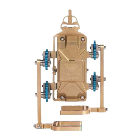
teching Craftsman DM17-S-T Technical specifications

组装手册
PRODUCT DESCRIPTION

Product name: Single-cylinder engine (overhead camshaft type)
Product model: DM17-S-T
Main materials: anodic aluminum oxide + stainless steel
Charging voltage: 10-20V DC
Battery capacity: 400mAh*2
Assembly diculty:
Product standards: GB/T9254-2008
GB/T17626.2-2006
Quality grade: A

Assembly instructions for Teching
Craftsman
“Teching Craftsman” is a metallic assembly model other than
a toy for playing only. It serves to improve hands-on skills of
children and youngsters, and let them learn common industrial
knowledge mainly. By keeping using our products, the user can
reach the goal of assembly – retting – creation in stages.
The requirements for product assembly are as follows:
◆ Perform assembly rigorously and orderly, keep the tabletop
tidy, look at drawings carefully, and pay attention to safety;
◆ If you have any doubt when adjusting any assembly
clearance or tightness after the completion of assembly,
please refer to our website or WeChat public account;
◆ The user is encouraged to modify part defects or tting
clearances, and apply lubricant under adult supervision to
further improve assembly;
◆ The user is encouraged to use simple material removal
tools (le, sandpaper, etc.) under adult supervision;
◆ The user is encouraged to modify or generally ret parts of
this product to enter the retting stage as early as possible;
◆ The user may disassemble this product and put it in the
package again according to the parts list attached hereto;
◆ If any part is lost, please inquire of or purchase it from us
(Teching store on www.taobao.com);
If you are willing to share with us, after completing product
assembly tasks of dierent diculty levels at dierent stages,
you will receive corresponding gifts, and have a chance to win
our special medals and take part in relevant events.

Safety Tips
1.Some safety awareness is required to use this product, and
improving safety awareness is also one of the functions of
this product;
2.This product is not intended for children below 8 years,
and adult guidance on assembly is recommended for children
below 10 years;
3. Use assembly tools rationally, assemble the parts in strict
conformity with the instruction manual, and avoid forcible
handling to avoid scratches; keep sharp points of tools or
parts away from the eyes to avoid contusions;
4.This product is made up of metallic parts mainly, and has a
certain level of hardness and a certain weight; please place it
properly to avoid bodily injuries;
5. During mechanical movement, do not put a nger or any
other part of the body within the movement range to avoid
contusions;
6.When any mechanical part is turning, do not put a nger or
any other part of the body beside it to avoid entanglement
and contusions;
7.Wire connectors must be connected according to the marks
specied in the instruction manual to avoid short-circuit or
failure arising from wrong connection;
8.Charge, discharge and place the battery as required; it is
advised to replace the battery when it has not been used for
3 months or more;
9.Do not prevent any part from running forcibly in any form; to
do this, turn o the power directly;
10.To ret this product, please pay attention to the relevant
part parameters, and avoid using any high-power electric part
that may result in an accident.

Contents
I. Basic knowledge on standard parts assembly………………1
II. Assembly instructions…………………………………..………3
1. Piston and connecting rod mechanism…………..…….…3
2. Crankshaft assembly ……………………………………..…6
3. Cylinder head assembly…………………………………….14
4. Camshaft, cylinder block and cylinder head assembly...18
5. Camshaft gear mechanism…………………………….…..21
6. Circuit system……………………………………………….25
7. Generator assembly ……………………………………….28
8. Mounting of timing belt (timing mechanism)…………...32
9. Guide pulley mechanism………………………………...…35
III. Adjustment of single-cylinder engine…………………....…39
IV. Basic structure and features of single-cylinder engine…40
V. Basic principle of piston engine…………………………..…42
VI. Parts list of single-cylinder engine………………………...49

I. Basic knowledge on standard
parts assembly
1. Mounting of screws
1
Right Rong
2. Mounting sequence of screws
Mount the screws diagonally in
order of number.
1 5 3
42
6

2
parallel push Oblique push
3.The method of installation of circlip
Yes(T) NO(F)
4. Lubricant mark
Where this mark is shown, it is recommended to apply create
to improve mechanical performance.

Connecting
rod (020)
Piston
(023)
II. Assembly instructions
1. Piston and connecting rod mechanism
1.1 Connection between piston and connecting rod
1.2 Mounting of piston pin
Piston pin
(022)
Piston
(023)
3

1.3 Mounting of snap ringAs shown below, insert the snap
rings into the snap ring slots on both ends of the piston pin.
Piston pin
(022)
Snap ring
(053)
4

1.4 Connection between connecting rod and crankshaft
M3 screw
(060)
Connecting
rod bearing
(021)
Piston
rod Assembly
(007)
1.5 Mounting of connecting rod bearing
5

(Assembly
completed)
Oil pump
turbine (024)
Turbine shaft
(038)
2. Crankshaft assembly
2.1 Assembly of oil pump turbine
6

End cap of
oil pump
(039)
M3 screw
(059)
Oil pump
tank
Oil pump
turbine
(024)
Front cover of
crankcase (001)
2.2 Connection of oil tank
2.3 Mounting of end cap of oil pump
7

2.4 Mounting of carrier gear shaft
Shaft
hole
Carrier gear
shaft (037)
(Assembly and connection within front cover completed)
8

2.5 Mounting of carrier gear and oil pump gear
Front cover of
crankcase
(001)
Carrier gear
(042)
Oil pump
gear (041)
Snap ring
(053)
Lubricant (2
positions)
2.6 Mounting of snap ring
9

Rear cover
of crankcase
(002)
Starting
motor
(016)
M1.6
screw
(062)
2.7 Mounting of starting motor
(Assembly and connection within rear cover completed)
10

2.8 Connection between crankshaft and rear cover of crankcase
Rear cover of
crankcase
(002)
Cranks
haft
(007)
Bearing
Lubricant (3
positions)
Locating
pin (057)
Locating
pin hole
2.9 Mounting of locating pin
11

Locating
pin (057)
Locating
pin (057)
Rear cover of
crankcase
(002)
Crankshaft (007)
Front cover
of crankcase
(001)
Locating
pin (057)
2.10 Assembly of crankcase
12

M3
screw
(058)
2.11 Mounting of connecting screws
(Assembly of crankcase completed)
13

3. Cylinder head assembly
3.1 Mounting of valves
Cylinder
head (008)
Valve
(032)
Valve
cover
(031)
Valve
spring (028)
Valve cap
(030)
3.2 Mounting of valve springs and valve caps
14

Spark
plug
(025)
Cylinder
head (008)
3.3 Mounting of spark plug
3.4 Combination of timing pulleys
Cam timing
base (012)
Cam timing
pulley (013)
Cam timing
cover pulley
(010)
M3
screw
(060)
15
Table of contents
Other teching Engine manuals
Popular Engine manuals by other brands
Mercury/Mariner
Mercury/Mariner Inboard 5.7 MPI ECT manual
Graco
Graco 204464 B Series Instructions-parts list
Mitsubishi
Mitsubishi TLE Series (FA instruction manual

Mitsubishi
Mitsubishi 6G7 user manual

ZIEHL-ABEGG
ZIEHL-ABEGG ZAtop SM210.60 operating instructions

Volvo Penta
Volvo Penta D3 Operator's manual
Mitsubishi Heavy Industries
Mitsubishi Heavy Industries Meiki TL Series instruction manual
Briggs & Stratton
Briggs & Stratton Vanguard 80000 Operator's manual

Grünwelt Maschinen
Grünwelt Maschinen GW Series owner's manual

Impco
Impco HHI Service manual
DR. BENDER
DR. BENDER EBL 33L manual

ZIEHL-ABEGG
ZIEHL-ABEGG ZAtop SM180.24/B Original operating instructions
