Chery SQR372 User manual

SQR7080 Maintenance Manual 372 Engine Mechanical System
Chery Automobile Co., Ltd
1
SQR372 Engine
Maintenance Manual
Chery Automobile Co., Ltd.
Forewords
In order to help the technical servicing personnel to have correct understanding and good command of the
cute Chery Model SQR7080 vehicle, and to master the skills for fast repairs and rational maintenance, a
special edition of the “Chery QQ Technical Service Manual—372 Engine Mechanics Division” is
compiled and published.
This Manual gives a detailed description on the dismounting, installating, checks and tests, adjustments
and diagnoses, technical standards and specifications for adjustments and diagnoses of various parts and
components as well as subsystems of Chery QQ 372 engines. This Manual is published by Chery
Automobile Co., Ltd.
Any parts or sections of this Manual shall not be copied or duplicated in whatever form or by whatever
approach without the written authorization of the publisher.
The right of interpreting the Manual belongs to the Service Department of Chery Car Marketing Co. Ltd
Editors
March of 2004
3、Special tools for maintenance:
Outer appearance Code and Name Purpose
Auxiliary devices for engine
dismounting and checks
Mounting onto engine
dismounting and check
stand
Engine dismounting and check stand Dismounting and
installing engine
Clockwise belt wheel wrench Camshaft clockwise
belt wheel dismounting
S
Spring bush pulling and removing
device
Installing crankshaft
oil seal

SQR7080 Maintenance Manual 372 Engine Mechanical System
Chery Automobile Co., Ltd
2
Throttle locking block removal
device
Auxiliary tools
Dismounting and
installation of throttle
spring locks
Flying wheel fixture
Dismounting and
installation of
crankshaft
Throttle guiding pipe punch
Removing and
installation of throttle
guiding pipe
Shaft oil seal replacer
S
T
Oil seal stand screw driver
Outer appearance Code and Name Purpose
Crankshaft belt wheel fixture Remove and install
crankshaft belt wheel
Wrench
Remove and install
can shaft slave gear
wheel
Replace throttle
spacing, adjust spacing
washer

SQR7080 Maintenance Manual 372 Engine Mechanical System
Water pump pulley assembly
wrench water pump Assembly
Measuring
tools
Feeler, gap gauge, caliper, ruler, cylinder gauge, gap ruler, pressure meter, torque
wrench
Tool Piston ring dismounting device
Oils Engine lubiricating oil, adhesion agents
Chapter 2 Timing Blet Service
1. Configuration diagram
1 Water pump pulley
2 Timing belt cover
3 Timing belt
4 Torsion shock absorber
5 Timing pulley damper
6 Tensioner
7 Crankshaft timing pulley
※ :Non-reusable part
Unit:N·m(kg·cm)
Chery Automobile Co., Ltd
3

SQR7080 Maintenance Manual 372 Engine Mechanical System
Remove torsional vibriation damper.
Remove water pump pulley.
Remove the water pump pulley according to the
illustration.
Remove with SST,if there are any.
Please remove with screwdriver and wrench
accordingly,if there is no SST at hand.
SST
Remove torsional vibriation damper
(1) Prevent the gear ring from rotating with SST.
(2) Remove bolt of torsional vibriation damper.
图29
Chery Automobile Co., Ltd
4

SQR7080 Maintenance Manual 372 Engine Mechanical System
Remove timing cover cap
Torque: 6±1N.m
Remove timing pulley damper
Remove the tensioner
(1)Carry out the operation at the upper thrust point
of compression of the first cylinder piston
(2) After removing the timing cover cap,turn the bolt
and rotate the timing gear clockwise with wrench,align
timing mark of camshaft timing gear with the cam
mark of camshaft cover cap;
Attention: You can rotate the engine clockwise
only,after installing the pulley;
Before removal,make a arrow mark on the position of
timing mark,assemble according to original state.
(3) Make sure that the crankshaft timing pulley wheel
mark is aligned with the mark of the oil pump.
(4) Remove the tensioner bolt, and take off the
tensioner
Do“mark”
Timing mark
Clockwise
Timing mark
Chery Automobile Co., Ltd
5

SQR7080 Maintenance Manual 372 Engine Mechanical System
Remove the timing belt.
[Caution] It is absolutely not allowed to use screw
driver or some other sharp-edged tools to remove the
belt.
Attention: Pay Attention to the following points while
using timing belt:
- Don’t bend the belt even at a small angle,otherwise
it will result in rope fracture inside the belt.
- - Service life of belt is short,don’t pollute the belt
with grease and water.
- You have no choice but rotate the engine
clockwise after installing the belt.
2.7 Remove the crankshaft timing gear
Chery Automobile Co., Ltd
6

SQR7080 Maintenance Manual 372 Engine Mechanical System
1 Make careful and detailed checks on the timing belt. Replace with new parts if any of the
conditions shown in the figure occurs.
(1)、Cracks on the back side rubber;
(2)、Cracks of teeth roots, cracks clearing off the fabric lining layer;
(3)、Tears and wears of fabric lining layer, missing rear teeth, broken teeth, etc.
(4)、Abnormal tears and wears on belt sides
Chap
Chap
Tears and
wears
Drop-off
of belt core
MIS
Abnormal
tears and wears
Chery Automobile Co., Ltd
7

SQR7080 Maintenance Manual 372 Engine Mechanical System
1 Even if the damages on the outer appearance can not be confirmed, the belt should be replaced
under any of the following circumstances:
(1)、If the water in the water pump is leaked, which makes it necessary to refill the water
continuously;
(2)、There are much oil stains on the belt, the belt should be replaced for the rubber will be
damaged when it is expanded;
Specifications and model of the timing belt
Model 372-1007081
Belt wide 25.3mm
Timing belt tensioner
Turn the belt tensioner supporting stand bolts to see if there are any abnormal sounds. Check to see if
there are any damages on the contacting surface of the belt.
Specifications and model of the timing belt tensioner
Model 372-1007030
Wide 27.0mm
Outside diameter φ50mm
Check to see if there are any damages on the outer appearance
Specifications and model of clockwise pulley
EF
Model
Item GL、ZL、GS、ZS
Diameter of camshaft timing
gear (mm)
φ110.7
+0.1-0.2
Diameter of crankshaft timing
gear (mm)
φ54.65
+0.7-0.13
2-3-4
Baffle of crankshaft timing gear
Check to see if there is any deformation
Standard size of crankshaft clockwisewheel:
Wide 28.6mm
Chery Automobile Co., Ltd
8

SQR7080 Maintenance Manual 372 Engine Mechanical System
Chery Automobile Co., Ltd
9
Installation
1 Installation of crankshaft timing gear
2 Installation of timing belt
(1)On the upper thrust point of the first cylinder
compression
① Place the camshaft timing gear around the front
end of the air exhaust camshaft so as to make the
positioning groove on the gear be aligned with the
positioning pin on the end surface of the camshaft.
Then use screws to fix the clockwise gear, with the
torque of 100 ± 5N.m.
(2) Make sure that the punched mark on the
crankshaft clockwise pulley is aligned with the mark
of the oil pump.
(3)Install timing pulley accordingly.
Timing mark
Timing mark
Timing mark
Clockwise
SQR7080 Maintenance Manual 372 Engine Mechanical System
Chery Automobile Co., Ltd
10
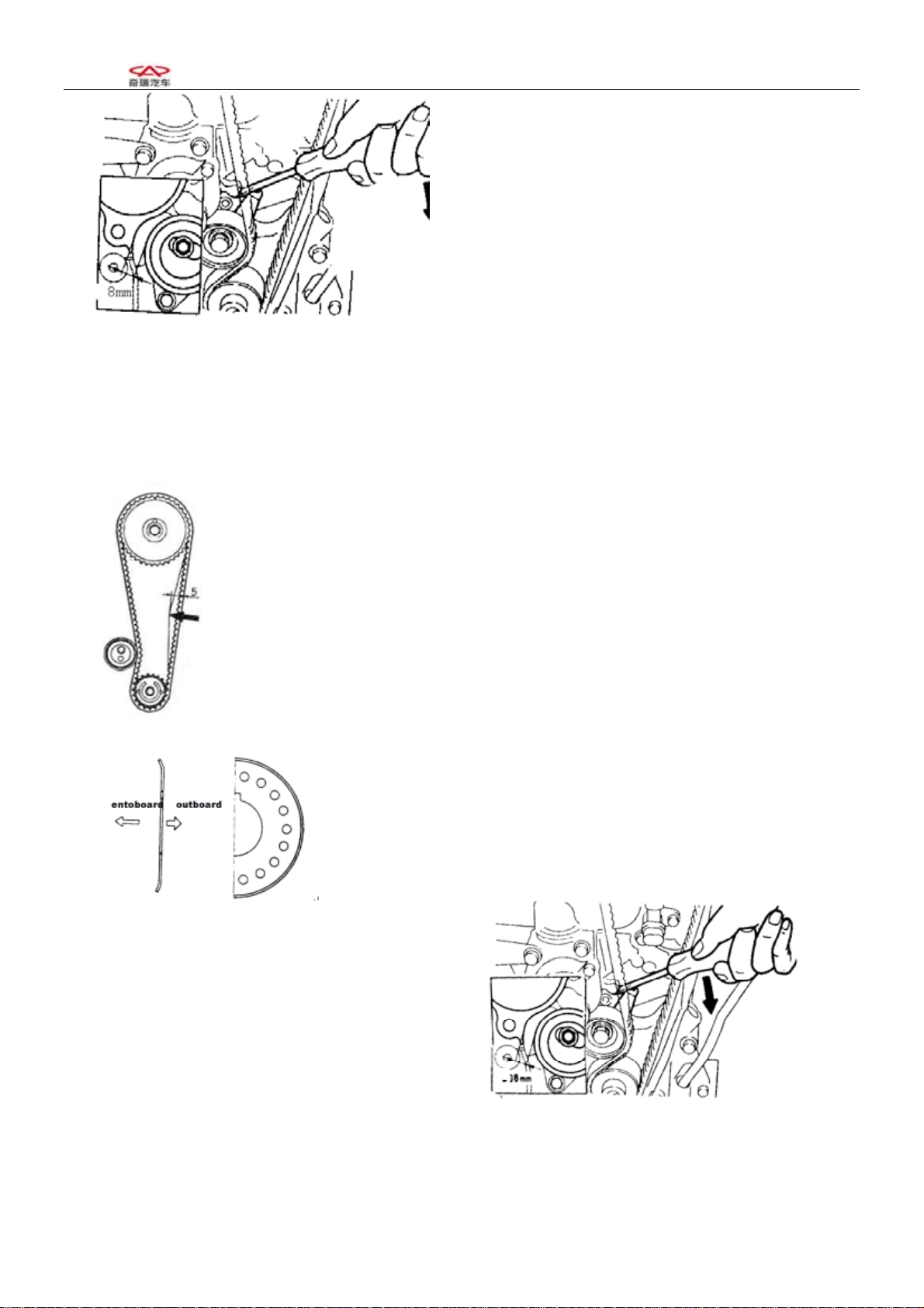
3 Install the tensioner
(1)Adjust the tension of the timing belt
As shown in the figure, make the space between the①
edge of the stretching wheel and the water pump case
arc to be about 8mm;
Tig②hten the bolt of the stretching wheel with a
torque of 25 ± 3N.m. Use a screwdriver to swing the
stretcher toward the right..
③Turn the crankshaft for two circles towards the
engine rotating direction, so that the camshaft pulley
and the crankshaft pulley matches the clockwise marks
respectively.
④Use hands to press down for about 5mm. The force
for pressing the clockwise belt is about: [Referrence]
20~30 N
Notice: When the deflection of the timing belt fails to
meet the specifications, the key is to adjust the
above-mentioned stretcher fastening bolt by widening
the spacing.
Tighten the S/A fixing bolt of the stretcher with the
specified torque of 25 ± 3N.m
4 Install the baffle of the crankshafte timing pulley
[Attention] Install the baffle towars the direction
shown in the right figure.

SQR7080 Maintenance Manual 372 Engine Mechanical System
5 Install the timing cover cap
Attention6±1N.m
SST
6 Install the torsional vibriation damper (use SST)
1)When there is no a flying wheel,
①Use the gear belt of SST to wrap part of the
crankshaft pulley .
②Lever of SST should be pulled to be immovable
(fixed),pay attention not to make the gear belt
moving,tighten the bolt according to the specified
torque of 98.0±10N.m{10±1kgm}
torque98.0±10N.m{10±1kgm}
SST
(4)、When there is a flying wheel,
①Use SST to prevent the toothed ring from turning
②Then tighten bolt of torsional vibriation damper.
3、Camshaft
3-1 Configuration diagram (the dismounting and installation of the clockwise belt are to be carried out in
the following procedures)
Chery Automobile Co., Ltd
11
SQR7080 Maintenance Manual 372 Engine Mechanical System
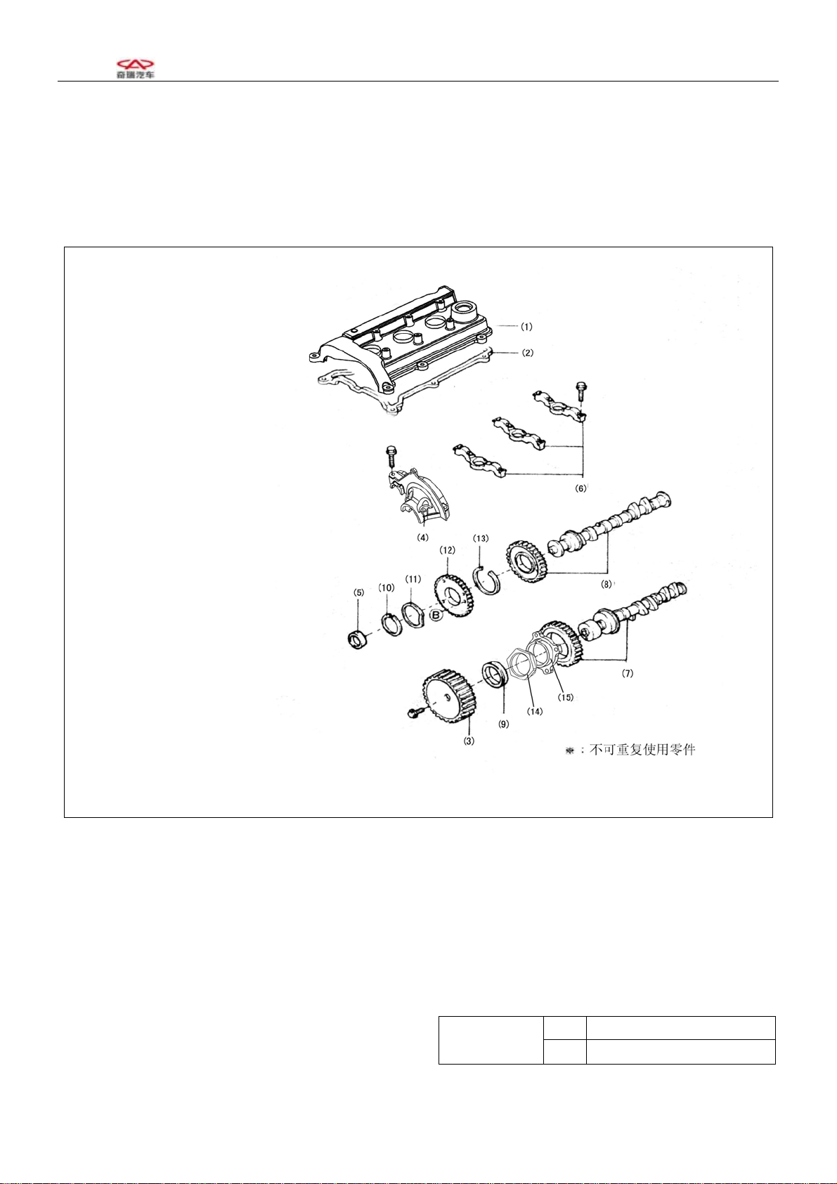
Chapter 3 Camshaft Service
3-1.Diagram ( Removal and installation order for timing belt)
(1) Valve cage cover
(2) Valve cage cover
gasket
(3) Camshaft timing
pulley
(4) Camshaft cover
(5) Circular plug
(6) Camshaft bearing
cap
(7) Exhaust camshaft,
(8) Intake camshaft,
(9) Oil seal
(10)Spring retainer
(11)Wave washer
(12)Iintake
camshaftsub-gear
(13)Snap ring
(14)Lock nut
(15)Flange
N
on-reusable part
3-2 Removal
Remove cylinder①
head cover assembly
Remove the valve chamber cover cap bolt
from two sides to the centre symmetrically.
Remove②valve chamber cover gasket
2 Routine check of valve
valve clearance standard:
IN 0.18±0.05
Va l v e
clearing EX 0.25±0.05
Chery Automobile Co., Ltd
12
SQR7080 Maintenance Manual 372 Engine Mechanical System
3 Use SST to dismount the camshaft clockwise gear
Attention· You must use SST to prevent the camshaft
from rotating.
Exhaust Intake
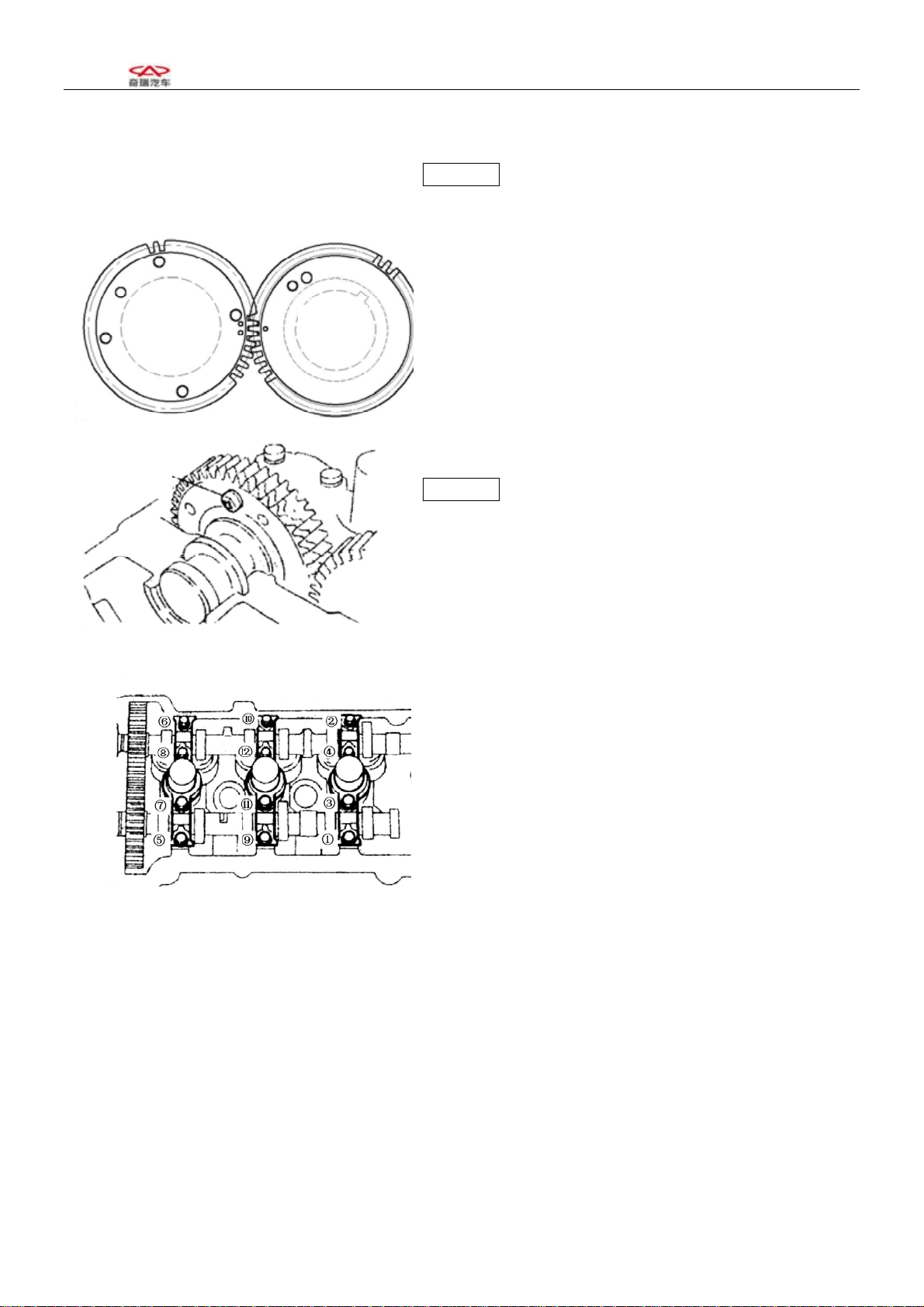
3 Removal of camshaft cover cap and camshaft
bearing cover
(1) Align the marks on the camshaft gears as shown in
the right figure.
Set bolt
(2)Use bolt to position the master and slave gears on
the air inlet camshaft, as shown in the right figure.
Attention In order to eliminte the radial force, keep the
camshaft in the leveled position before dismounting it
(to avoid possible damages caused by excessive radial
forces)
(3)Remove the bolts in the sequence shown in the
right figure;
Remove the camshaft bearing cover
(4)Remove the spark plug
(5)Remove the camshaft slave gear. Use the special
tool as shown in the right figure.
Clip the camshaft tightly,use pin of SSTto insert the
two pin holes of the gear;turn the gear,to keep the bite
state of master and slave gear;remove the fixing bolts of
slave gear.
[Attention] Do not damage the surface of the camshaft.
Chery Automobile Co., Ltd
13

SQR7080 Maintenance Manual 372 Engine Mechanical System
Chery Automobile Co., Ltd
14
SST
(3) Use tensioning apparatus to remove the bearing use
elastic snap ring,remove wave washer and teethed ring.
3-3 Camshaft
1 Use the caliper to measure the height of the camshaft.
If it is below the specified limits, make proper
replacement.
Camshaft Unit:mm
EF
Model
Item
ZL、
RL
GL、GS、
ZS
IN φ23.0
-0.02-0.033
Standard
EX φ23.0
-0.02-0.033
IN
φ
22.9
Limit EX φ22.9
2 Checks on camshaft axial clearance
(1)、When the axial spacing is measured with a cliper
to be larger than the benchmark value, the camshaft is to
be replaced.
The air inlet camshat axial clearance is 0.1~0.170mm。
The air exhaust camshaft axial spacing is 0.1 ~
0.173mm。
Limits for operation:0.18mm
3-4 Cleaning
1、Clear off the spark plug carbon accumulation with a
metal brush.

SQR7080 Maintenance Manual 372 Engine Mechanical System
3-5 Installation
①Under the circumstance of using SST,use the special
tools for fixing at the twoφ6 holes of the camshaft gear
S/A.
②Turn the slae gear to the right, match the mark hole
on the slave gear with the mark on the master gear, or
align the marks on the slave gear with the mark on the
master gear; then fix the slave gear with bolt. (thread:
M5; pitch: 0.8)
SST
2、Installation of the camshaft
[Attention] Size of the axial clearance of the camshaft
(1)、Smear lubricating oil at the camshaft gear section
and the cylinder cover axial diameter section.
(2)、Fix the camshaft slave gear by roughly adjusting on
the cyliner cover.
(3) It is necessary to measure the size of axial clearing
of camshaft.
Exhaust Intake
(4)Install camshaft,the timing mark must be aligned
shown as the right figure.
(5)Smear lubricating oil on the camshaft assembly, the
gears and the cyliner head axial diameter section.
3 Tighten the camshaft bearing cap shown as right
figure.
4 Remove the bolt for fixing the slave gear of the
camshaft assembly.
Chery Automobile Co., Ltd
15

SQR7080 Maintenance Manual 372 Engine Mechanical System
Chery Automobile Co., Ltd
16
SST
5 installation of camshaft head cap
Smear the fluid sealant on the camshaft head cap section
(with oil groove) shown as the right figure.
Tighten the bolts according to the sequences shown as
the right figure with the specified torques.
6 After smearing oil in the plug cap hole and assembling
surface of the plug,use SSTto press the plug lid
Attention· Install the plug lid shown as the right
illustration.
Keep unbiased with cylinder head end surface after
pressing.
outside
7 Smear engine oil on the oil seal installation port of
cylinder head,camshaft oil seal edge of blade and outside
ring,use M10 bolt (length 50-60 mm) and SST press the
cylinder,lower 1mm thatn the end surface of the
cylinder4 head.
Attention ·Under the condition of use the oil seal
repeatedly,press here with engine oil adhesive agent
- The oil seal should not be pressed inclining to one side.
Sealing line

SQR7080 Maintenance Manual 372 Engine Mechanical System
8 Installation of the timing gear of camshaft
After smearing the fluid sealant,use SST to prevent
rotating,tighten the timing gear bolt of camshaft
according to regulated torque of 100±5N.m.
9 Installation of valve chamber cover cap
The used base facing the cylinder cover of the timing⑴
belt cover must be cleaned thoroughly.
Install the new base correctly into the groove of the⑵
valve cage cover cap
Install valve cage cover cap to cylinder head⑶from two
sides to the centre symmetrically according to the
regulated torque of 6±1N.m
1 Use feeler gauge to check the throttle clearance.
Attention·Make sure to measure the clearance between
basic circle of cam and valve adjusting gasket.
Standard of valve clearance :
IN 0.18±0.05
valve
spacing EX 0.25±0.05
1 When it is beyond the benchmark value, the
adjustment washer has to be replaced and the clearance
should be adjusted.
[Attention] The valve number that goes beyond the
benchmark value has to be recorded, and the result of
measurements should be recorded as welll
(1) Use a caliper to measure and adjust the thickness of
the separation cushion.
SST
Chery Automobile Co., Ltd
17

SQR7080 Maintenance Manual 372 Engine Mechanical System
Chery Automobile Co., Ltd
18
(2)Select proper separation cushion on the basis of the
throttle thrusting rod benchmark values.
①IN
Selected cushion thickness = removed cushion
thickness + (measured throttle spacing – 0.18mm)
EX②
Selected cushion thickness = removed cushion
thickness + (measured throttle spacing –
0.25mm)
[Reference] there are 32 kinds of shim is thickness ,
shown as the illustration
2.18 2.40 2.62
2.20 2.42 2.64
2.22 2.44 2.66
2.24 2.46 2.68
2.26 2.48 2.70
2.28 2.50 2.72
2.30 2.52 2.74
2.36 2.58 2.80
2.32 2.54 2.76
2.38 2.6
(7) Use the selected adjusting gasket to adjust the
throttle clearance.
[Attention] Install the the feeler with the identification
mark facing downwards.
Forword
low er
(1) Turn the camshaft,make the cam lobe upwards to
make things convenient for replacing the gasket,make
the valve thrusting rod gap towards the inside.
(2) Turn the crankshaft and the bulging top of the cam
presses down the valve thrusting rod.
Valve lifte
r
nick

SQR7080 Maintenance Manual 372 Engine Mechanical System
Chery Automobile Co., Ltd
19
(3) Put SST on the valve thrusting rod from inside of
cylinder head,pay attention noy to press the adjusting
gasket,shown as the illustration.
(4) Turn the crankshaft to make the top of the cam
vertically upwards. Use special tools to press down the
valve thrusting rod and hold it in the place firmly.
(5) Use a screwdriver to stir up the separation cushion,
and use magnet bar to remove the separation cushion
from inside.
(6) Turn the crankshaft to make the cam top facing
downward. Press down the valve and use special tools to
remove it.
(7) Turn the crankshaft for 2—3 circles, then confirm
the throttle spacing. If it fails to be within the benchmark
value limits, check and adjust the throttle spacing in the
operational procedures described in (1)—(9).
SST
SST
SST
4. Cylinder head
4-1 Configuration diagram (Do the following operations in the procedures for the dismounting and
installation of the camshaft)

SQR7080 Maintenance Manual 372 Engine Mechanical System
(1) Spark plug20±1Nm
(2) Cylinder head
(3) Weather sealI
(4) Cylinder head gasket
(5) Adjust shim
(6) Valve lifter
(7) Keeper
(8) Valve spring seat
(9) Valve spring
(10) Iintake valve
(11) Exhaust valve
(12) Valve oil seal
(13) Valve seat
(14) Valve guide
※:
Non-reusable part
Unit:N·m(kg·cm)
4-2 Dismounting
1、Removal of spark plug
Chery Automobile Co., Ltd
20
Other manuals for SQR372
1
Other Chery Engine manuals


Popular Engine manuals by other brands


Nice
Nice Era Star P Series Instructions and warnings for installation and use

Stiga
Stiga TRE 352 Operator's manual

Tecumseh
Tecumseh OHV140 Operator's manual

Pentair
Pentair PENTEK 76PM2-50-4 owner's manual

YANGDONG
YANGDONG YD380D Operation & maintenance manual

Sumitomo Drive Technologies
Sumitomo Drive Technologies IB Series manual