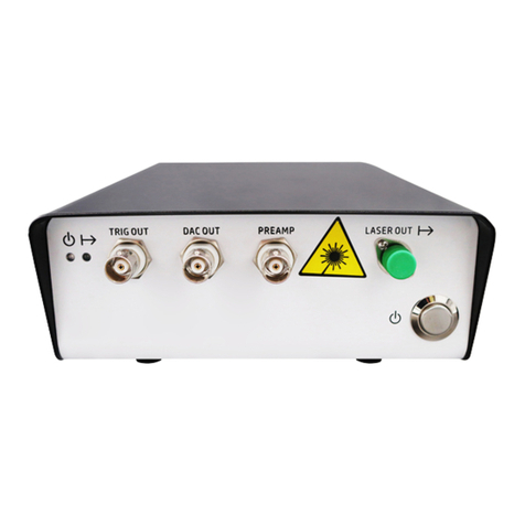
Techmach AWG5000 User manual


ጝሁႠీ!ൽጆ
1
Tale of Contents
Quick instructions for ultrasonic sensor or infrared sensor......................................Inside Front
Photoelectric sensor Techmach LS80 Manual......................................................OUTside Front
Safety and Warning....................................................................................................................2
Introduction..................................................................................................................................5
Technical specification..............................................................................................................7
Installation and Adjustment.......................................................................................................9
Troubleshooting............................................................................................................................22
Operation......................................................................................................................................13
Maintenance...............................................................................................................................24
Shipping and Storage................................................................................................................24
Warranty Policy & server after sale.......................................................................................... 25
Appendix I..................................................................................................................................................................................26
Appendix II.................................................................................................................................................................................27
Appendix III................................................................................................................................................................................28
AW5000 control enclosure................................................................................................................15

ጝሁႠీ!ൽጆ
2
Safety and Warning
Make sure carefully read this manual before your installing, wiring, starting, operating or making practices while
operating and maintaining this unit. Please operate the web guiding control system with necessary skill and complete
awareness of the Safety and Warning, make sure not operated by unqualified person.
We used signal words WARNING and CAUTION to indicate Hazard seriousness levels asfollows:
WARNING: is used to indicate the presence of a hazard, which can cause severe personal injury,
death, or substantial property damage if the warning is ignored.
CAUTION: is used to indicate the presence of a hazard, which will or can cause minor personal injury
or property damage if the warning is ignored.
However, please comply with instruction strictly no matter CAUTION or WARNING, as huge damage maybe caused
even if ignoring the CAUTION content.
PRIHIBIT and MANDATORY symbols are defined follows:
PRIHIBIT: Make sure NOT to do. For example: we use to indicate the warning “ No Kindling”.
MANDATORY: Make sure to do strictly. For example: we use to indicate the warning “EARTHING ”.
In this manual, we use signal words NOTE to indicate other functional Warnings, which maybe not cause property
damage, but still need your full attention. Please put this manual at the place where easy to get.
1. Read the fallowing carefully to defend against electric shock
WARNING
zz
zz
zMake sure the power supply is switched off first and verify that no supply voltage reserved on the switch
power with a multi-meter before your wiring or examination, otherwise serious electric shock may
be caused.
zz
zz
zMake sure the switch power earthed completely.
zz
zz
zWiring and examination may only be operated by the qualified person.
zz
zz
zMake sure the wiring only and must after installation of the viscosity control enclosure, otherwise the
serious electric shock may be caused.
zz
zz
zMake sure not damage or haul the cable, also unable to crush or hang the cable with heavy materials,
otherwise the serious electric shock may be caused.

ጝሁႠీ!ൽጆ
3
2.Read the fallowing carefully to defend against the fire:
zz
zz
zMake sure not use any tinder to install switch power or web guide control enclosure, otherwise a fire may
be caused.
zz
zz
zMake sure switching off the power supply first while any faults happens with the switch power or web
guide control enclosure. Otherwise, continue power-on may cause the fire.
3.Read the fallowing carefully to defend from damage:
1).Make sure input voltage of switch power comply with this instruction, otherwise serious damage to the switch power
may be caused.
2).Make sure correct wiring polarity (+, -), otherwise serious damage to the switch power may be caused.
4.Other warnings:
Please pay attention to follows, any error operation may cause serious personal injury, device damage or electric shock.
1).Transit and installation
zz
zz
zPlease use correct transport method based on weight of the device itself.
zz
zz
zMake sure not pile up over the reasonable quantity.
zz
zz
zMake sure to install the device at a firm place with the install methods described in this instruction.
zz
zz
zMake sure not stand on this device or put heavy material on the device.
zz
zz
zMake sure the device to be far away from any falling or impingement.
Operating environment:
Web Guiding Control enclosure and sensors:
Ambient temperature: -10 to +50 (Non-freezing)
Ambient Humidity: Less than 90% RH (Non-condensing)
Storage Temperature: -20 to +65 (Non-freezing)
Storage Humidity: Less than 90% RH ( Non-condensing)
Operating altitude: Less than 1000 m
Passline vibration: Less than 5.9m/s2
Linear Actuator :
Ambient temperature: -10 to +50 (Non-freezing)
Ambient Humidity: Less than 90% RH (Non-condensing)
Deposit Temperature: -20 to +65 (Non-freezing)
Deposit Humidity: Less than 90% RH (Non-condensing)
Operating altitude: Less than 1000 m
Passline vibration: Less than 5.9m/s2
cc
cc
c c
cc

ጝሁႠీ!ൽጆ
4
Caution:
zLinear Actuator and the sensor should be fastened on the mechanism firmly, otherwise will effect the
accuracy, even caused serious damage to this device.
zAs for installation of linear actuator, please distinguish the position between R end (fixed) and F end
(unfixed), otherwise serious damage to this mechanism will be caused, even rejected.
zWe suggest the user use specific adjusting bracket to finish the installation, and make sure a firmly
installation, otherwise will effect the accuracy or caused damage badly.
2). Wiring
Caution:
Make sure correct wiring connection, otherwise, the damage to switch power or viscosity control enclosure
maybe caused.
3). Initial operation and adjustment
Caution:
zPlease adjust and confirm your parameter setting before running, otherwise, unexpected affair maybe
happens.
zz
zz
zAny extreme parameter adjustment or change will cause an unstable running.
4). Operating
Caution:
zTo insure a timely running-stop and switching-off power supply immediately, please set outer
urgent-pause- switch.
zMake sure NOT disassemble this device for maintenance by any unqualified person.
zMake sure NOT to refit the device.
5).Abnormity handling
Caution:
Refer to the trouble shooting chapter first when fault happens, and eliminate the trouble according to
solution in this instruction. Make sure to verify the security before rerunning the device.
6).Waster handling
Caution:
Please handle the waster as a kind of general industrial waste.

ጝሁႠీ!ൽጆ
5
Introduction
AWG5000 is a high performance web guiding system with high accuracy, stability and reliability and quite simple to install
or operate. This system is compatible with Techmach’s compensated ultrasonic edge detectors, compensated IR edge
detectors and Linear Actuator.
Addition,AWG5000 support Ethernet, CAN and RS485 network communication and allowed to be remotely controlled by
a remote station or terminal.
A typical AWG5000 controlling system including four main components:
1.Web guide control enclosure
zThe control board is opto-isolated with PWM motor board, which enhances system’s reliability;
zThe System could save up to 128 unique non-volatile memory for user’s settable parameters and operating modes, and
auto-recovery after power interruption;
zOn-board parameter entry touch keypad control and 5 digits of LED display in bright blue colo;
zActuator end-of-travel limit:
Potentiometer input for electronically-adjustable limits;
Limit switch inputs for adjustable limits;
zInput voltage: 24VDC, 12VDC;
zNetwork:THERNET,CANBUS,RS485.
2.Switch power supply
zSwitch-selectable input voltage: single-phase, 220 20% VAC, 50HZ;
zOutput voltage: 24VDC [+V1 –V1]; 12VDC[+V2 –V2]
Caution:
zz
zz
zThe information contained herein is accurate at the time of publication, Techmach reserves the right to
make design changes to equipment described in this manual at any time and without notice.
zz
zz
zThe technician should comply with local rules during the installing process.
zz
zz
zThis mechanism should be installed, activated and operated by qualified person.
zz
zz
zRemove manually allowed.
+
-

ጝሁႠీ!ൽጆ
6
3.Edge Detector
1).Compensated ultrasonic Edge Detector
zFully compensated for temperature, humidity, dust, and most other process contaminants, and no manual operation
needed;
zImmune to passline variation and web flutter;
zIdeal for transparent or opaque film, paper, foil web materials.
2).Compensated IR Edge Detector
zFully compensated for temperature, humidity, dust, and most other process contaminants, and no manual operation
needed;
zImmune to passline variation and web flutter;
zIdeal for non-wovens and other opaque porous web materials.
4).Linear Actuator
zTechmach’s actuator is belt-driven and ball-screw designed for superior reliability and precision. The actuator uses a
ball bearing as its driver to make sure smooth motion & precise position. High industrial-grade thrust bearing are used in
all actuators. This special thrust bearing was used to trundle, enable a long lifetime and reliant running achieved
zThe center position of actuator is adjustable within the safe end-of-travel limit, more flexible and facility.
zDC Servo drive motor made the actuator respond more rapid and accurate
zFull product series optional
zSuitable for every web guide, unwind or rewind roll frame
Technical Parameters (Standard Specification)
Power supply: DC24V
Operating Temperature: - 10 ~ +50
Humidity: Less than 90% RH
Enclosure Size: (W HD) 190mm 220mm 90mm
c
c

ጝሁႠీ!ൽጆ
7
Technical Data
1.Web Guiding control enclosure
Power supply: 24VDC 1%,12VDC 1%;
Rated power consumption:120VA;
Enclosure: Protection class is IP54, embedded installation mode and wall-hanging installation mode is optional;
Splice performance: remote control allowed;
On-board entry keypad function:
Parameter setting
EdgeAselect
Edge B select
Centerline select
Actuator Retract
Actuator Extend
Automatic Mode
ManualMode
Auto-center Mode
Ambient Temperature: -10 ~50
Humidity: 0~90%, Non-Condensing;
Accuracy: within 0.1mm;
Web guiding speed: 25 mm/s;
Max drive load: 3000 kg.
2.Edge Detecter
Splice mode: selectable simulate or digital I/O (digital algorithms);
Temperature Range: -10 ~50
Response time: 4 milliseconds;
Material: electro-aluminum sheet, Chemical synthetic materials.
+
-+
-
cc;
c c

ጝሁႠీ!ൽጆ
8
3.Linear Actuator
Example of confirming the parameter:
Mode:
Max end-of-travel:
Max load rating:
Max Thrust
300 1500 3000
30 150 300
Type Load End-of-travel

ጝሁႠీ!ൽጆ
9
Installation and Debugging
Installation:
Note:
Make sure NO any electrical connections exits before the mechanism installation.
1).Control Enclosure (Refer to application drawing on appendix I)
zInstall the control enclosure on a rigid mount such as a wall or secure framework.
zDon’t install the control enclosure on the side of a dryer or in other high temperature areas.
zAlso, don’t install the control enclosure on a moving winder structure, such as unwind or rewind guide frame.
The cables supplied with the system have been chosen for specific shielding and capacitance properties. Do
not splice or replace these cables with any other style or configuration or cable, this can cause serious
degradation or complete loss of system performance. Do not splice cables. Long cables are available upon
request.
AW5000 control enclosure offers two kinds of installation modes:
embedded installation and wall-hanging installation
Embedded installation mode: Refer to appendix I for hatch size of mount. Fasten the inserted control enclosure with
the bow-angled accessory which is delivered together with the device.
Wall-hanging installation mode: Refer to appendix I for more. Install the web guide control enclosure to the given
position with the bolts.
100mm

ጝሁႠీ!ൽጆ
10
2).Linear Actuator
zTo Fix theActuator on both ‘R’ end and ‘F’ end, note ‘R’ is the fixed connection end, connecting with static parts, and ‘F’
end is the hinge joint end, connecting with the parts needed to move oppositely.
zWhen wall-hanging installation mode, drive motor ‘M’ should be subjacent. when embedded installation mode, the drive
motor ‘M’ should adopt assist-holding
zFurther to the safety consideration, we suggest the user installing a mechanical end-of-travel limit switch.
Side fixed plate Side fixed plate
RF
M
Note:
Make sure the actuator is in the servo-center position before installing the web guide. This may be
impossible until after static test.
CAUTION:
Special attention must be given to the actuator mounting. Any mechanical compliance or backlash in the
actuator mounting will seriously affect guiding accuracy. Deflections of a few thousandths of an inch will
reduce the performance of the system.
3). Edge Detector Sensor
zInstall the edge detector sensor . Refer to the edge detector sensor application drawings for the correct mounting
dimensions and position.
zTo simplify installation and adjustment, we suggest users select the auxiliary brackets supplied by TECHMACH.
zThe sensor cable should be long enough so that the sensor may be repositioned if the web width or web path changes.
The standard cable length is 4m. Longer cables are available upon request.
Application drawing on Appendix II shows how to install the Edge Detector.
Gjyfe!qmbuf
Bouj.xfbs
nbufsjbm
Bouj.xfbs
nbufsjbm
Tupq!cbggmf
Tjef!gjyfe!qmbuf
Frontview Side view

ጝሁႠీ!ൽጆ
11
TerminalName
Terminal code
wiring color blue Green Brown Red Yellow
User’s wiring
CAUTION:
If the actuator or guide mechanism hits a mechanical obstruction before the actuator stops automatically
at its end-of-travel limit, release the button immediately. Continued activation will cause serious damage
to the actuator motor and/or guide mechanism.
4).Switch power supply
CAUTION:
Make sure the terminal earthed with PE( protect earth) completely.
Adjustment
Refer to connection drawing of Appendix V to complete the whole electric connection.
Static Test
a).Turn the power switch on;
b).Press the MANUAL button;
c).Press the IN and Out buttons several times. The actuator and web guide mechanism should move freely and
without hesitation;
d). Press and hold the IN button. When the guide mechanism gets near the In limit, release the button;
e). Jog the IN button repeatedly until the actuator automatically stops at its end-of-travel limit.
f). Repeat the previous two steps using the OUT button to check the Out limit.
g). Press the CENTER button and verify that the actuator drives to the center of its stroke.
Dynamic Test
a).Press CENTER button and verify that the actuator drivers to the center of its stroke. This also places the web guide in
its center (or tram) position;
b).Thread the web through the machine and put a slight tension on it so the web is in its normal operating position.
Repeat steps c) through f) for each sensor;
c).Press the CENTER button;
d).Position the sensor.

ጝሁႠీ!ൽጆ
12
zz
zz
zEdge Detector: Place at the edge of the web. The edge detector’s null indictor LED will turn off when the edge detector
is positioned correctly. The scribed lines on the edge detector indicate the approximate location of the detector’s guide
point.
Note
The default calibration supplied with the system should work for most materials. However, if the null
indicator LED does not turn off the detector may need to be calibrated.
e).Press the AUTOMATIC button
f).Move the sensor left or right slowly and observe how the guide reacts. The guide should move the web so that it
follows (or chases) the movement of the sensor.
zz
zz
zEdge Detector: The guide should move the web so that the edge of the web is always aligned with the edge
detector’s guide point.
Note:
If the web guide does not follow the movement of the sensor and moves in same direction with offset of web
materials, then the sensor polarity not correct and must be changed. Refer to the system configuration
section of this manual for more information.

ጝሁႠీ!ൽጆ
13
Operation
The AWG5000 may be configured for a wide variety of applications, but most configurations share the same basic
operating procedure:
1).Press the Center button and wait for the web guide to drive to the center of travel.
2).Thread the web through the machine.
3).Position the sensors.
zz
zz
zNarrow array edge detector: Place the detector near the edge of the web. Move the detector towards the web until
its null indicator LED turns off.
Note:
The scribed lines on the edge detector indicate the approximate location of the detector’s guide point.
zz
zz
zTwo edge detectors (Centerline guiding): Press EDGE-A button, Place detector A near the edge of the web.
Move detectorAtowards the web until its null indicator LED turns off. Press EDGE-B button, Place detector B near the
opposite edge of the web. Move detector B towards the web until its null indicator LED turns off.

ጝሁႠీ!ൽጆ
14
4).Sensor’s operation modes, see configure of parameter 10 for more information.
5).Press AUTO button. The system will now guide the web in Auto mode.
6).System configuration:
a).verify the wiring connection carefully before turning on the power supply.
b).Note that the LED display will show dashes ‘- - - - -’ immediately after power is turned on, the dashes indicate that no
parameter is currently selected for examination or adjustment, but that the system is operating normally.

ጝሁႠీ!ൽጆ
15
4).Operating modes:
(AUTO): AUTOMODE;
(CENTER): CENTERMODE;
(MANUAL): MANUALMODE.
The parameters of AWG5000 control enclosure are described below:
0).Web compensation enable bit.
Parameter code number:00
The default setting is for Web Guiding Control.
Note that the display screen will show “00-00” immediately
after power is turned on and after the SETUP button is
pressed, now the system enters into the parameter setting
course;
(The front two digits of ’00-00’ means the parameter code
number, the later two digits means data value corresponding
to the parameter code number.);
Press the OUT or IN buttons so that you could select the
parameter you want to examine and/ or adjust. Each param-
eter has a unique code number.;
Press SETUP button to activate configure of a certain pa-
rameter code number;
Press the OUT or IN buttons to adjust the parameter value;
Press SETUP to store the new data value in non-volatile
memory;
To leave the data value at its original value press ESC;
zz
zz
z
zz
zz
z
zz
zz
z
zz
zz
z
zz
zz
z
zz
zz
z

ጝሁႠీ!ൽጆ
16
1).Input A Polarity
Parameter Code number: 01
Parameter Range: [0, 1], the default value is 0
0 — The actuator will move out when edge detectorAis blocked, or the Eagle Eye I sensor’s sight point is to the left of
the line or edge it is following.
1 — The actuator will move out when edge detectorAis unblocked, or the Eagle Eye I sensor’s sight point is to the right
of the line or edge it is following.
2).Input B Polarity
Parameter Code number: 02
Parameter Range: [0, 1], the default value is 0
0 — The actuator will move out when edge detector B is blocked, or the digital line guide’s sight point is to the left of the
line or edge it is following
1 — The actuator will move out when edge detector B is unblocked, or the digital line guide’s sight point is to the right of
the line or edge it is following
3).Maximum Deadband
Parameter Code number: 03
Parameter Range: [0-99 ],the default value is 28
The Maximum deadband is a zone around the sensor guide point where the motor drive is turned off. The higher the
Maximum Deadband value is set, the farther the web edge or line must move away from the guide point before the motor
drive is turned on. This parameter is typically used to compensate for edge curl and web flutter. The Maximum Deadband
value must be higher than the Minmium Deadband value.
4).Minimum Deadband
Parameter code number: 04
Parameter range: [ 0-99 ] The default value is 14
The minimum deadband is a zone around the sensor guide point that the web edge or line position enters this zone, it
must then move outside of the Maximum deadband zone before the motor drive is turned on. The minimum Deadband
value must be lower than the Maximum Deadband value.
5).Auto-Mode Speed Limit
Parameter code number: 05
Parameter range: [20-60], the default value is 26
This parameter limits the max speed of the actuator inAutomatic mode, the higher this value is, the faster the actuator
can move.
6).Manual-Mode Speed
Parameter code number: 06
Parameter range: [15-60], the default value is 30
This parameter determines how fast the actuator will move in Manual and Servo-Center mode . The
higher this value is, the faster the actuator will move.

ጝሁႠీ!ൽጆ
17
7).Manual Polarity
Parameter code number: 07
Parameter range: [0, 1], the default value is 0
0 — The actuator extends when the OUT mode is selected, and retracts when the IN mode is select
1 — The actuator extends when the IN mode is selected, and retracts when the OUT mode is selected
8).Power-up Mode
Parameter code number: 08
Data: [0-2], the default value is 0
0 — The system will power-up in Manual mode
1 — The system will power-up in Servo-Center mode
2 — The system will power-up in the same operating mode that was selected when last powered-down
9).Edge-Loss and Line-Loss Detection
Parameter Code number: 09
Data: [0, 1], the default value is 0
0 — Edge-Loss and Line-Loss detection are disabled
1 – Edge-Loss and Line-Loss detection are enabled
10).Sensor operation mode
Parameter Code number: 10
Parameter range: [0-3], the default value is 0
0 – Sensor on the mode of edge
11).Sensor’s regular interval
Parameter code number: 11
Parameter Range: [4-20], the unit is ms, the default value is 4ms
This parameter determines the sensor’s regular interval.
12).compensate time
Parameter code number: 12
Parameter range: [ 0-20], the default value is 0
This parameter is typically used to adjust the compensate time for edge defect, and the motor drive is turned off during
this compensate time, the motor drive is turned on after this compensation. Make sure Parameter 9 (Edge-Loss and
Line-Loss Detection) to be configured before enable this parameter.

ጝሁႠీ!ൽጆ
18
13).reserved for future use
Parameter code number: 13
14).reserved for future use
Parameter code number: 14
15).reserved for future use
Parameter code number: 15
16).reserved for future use
Parameter code number: 16
17).Recover the factory configure
Parameter Code number: 17
Parameter range: [0, 1], the default value is 0
0 – Default parameter configure disabled;
1 – Default parameter configure enabled.
18). Reserved for future use
Parameter code number: 18
19).Software Version
Parameter Code number: 19
This parameter displays the software version.
20).Software Version
Parameter Code number: 20
This parameter displays the software version.
21). Keypad lock/unlock
Parameter Code number: 21
Parameter Range: [0-1], the default value is 0
0 - - Keypad lock disabled;
1 — Keypad lock enabled.
When activate this parameter, press and hold ESC button for 5 seconds, the keypad will be locked, parameter configure
could not be modified, excepting press and hold ESC button for 5 seconds to unlock the keypad, then start the parameter
configure course.
22).Software Version
Parameter Code number: 22
This parameter displays the software version.
Table of contents
