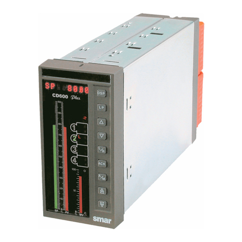
SMAR CD600 Plus User manual

Instalação mecânica do controlador
A gura 1 mostra o CD600 PLUS inserido
na abertura do painel (Vista de frente
do painel).
A gura 2 mostra a chave de fenda e o
parafuso da presilha do CD600 PLUS (Vista
de trás do painel)
A gura 3 mostra as presilhas inferior e su-
perior inseridas nas aberturas da carcaça do
CD600 PLUS para xá-lo no painel.
A gura 4 mostra a forma correta para
amarrar os cabos na parte traseira do
CD600 Plus, caso contrário, obstrui-se
o acesso aos resistores shunt.
Acesso livre a
conguração do
resistores shuts
Presilha Superior
Presilha Superior
Presilha Superior
Presilha
Inferior
Instalação elétrica do controlador
As guras 5 e 6 mostram as etiquetas coladas na lateral do CD600 Plus, modelo AC e DC, respec-
tivamente. Veja pelas legendas destas guras os signicados dos bornes.
Figura 5 - Etiqueta lateral com o diagrama de bornes para o CD600 Plus modelo AC.
Figura 6 - Etiqueta lateral com o diagrama de bornes para o CD600 Plus modelo DC
Para inserir o o de conexão das entradas/saídas e comunicação no bloco de terminais, proceda
de acordo com os seguintes passos:
1. Insira a chave de fenda na cavidade retangular do bloco de terminais (Não force a chave
de fenda na lateral do bloco, pois pode danicá-lo).
2. Gire a chave de fenda num ângulo de 90º. A cavidade para inserção do o abrirá.
3. Insira a parte descascada do o na cavidade e gire a chave de fenda novamente no sentido
oposto para “prensar” o o na cavidade.
Figura 7 - Bloco dos terminais do CD600 PLUS com seus terminais fechados e abertos.
Configuração da Estratégia de Controle
Consulte o manual do CONF600 para instalar o software de conguração.
Implementando a comunicação entre o controlador e o computador
1. Usando a porta serial do computador
Conecte a interface ICS 2.0P no terminal identicado na etiqueta do CD600 Plus com o
cabo especíco. (Consulte o manual da ICS 2.0P para maiores detalhes).
Figura 8 - Diagrama de ação do CD600 PLUS com a interface ICS2.0P.
2. Usando a conexão Ethernet
Para estabelecer uma conexão Ethernet, conecte a interface ENET-710 no terminal RS485
do CD600 Plus. Veja a gura 9. Rera-se ao manual do ENET-710 para maiores detalhes.
Consulte a seção de comunicação do manual do usuário do CD600 Plus para maiores detalhes
sobre a conguração dos blocos de comunicação.
smar
www.smar.com.br
C D 6 0 0 P L U G P
Figura 9 - Diagrama de ação do CD600 PLUS com a interface ENET-710.
NOTA
Insira somente o o descascado na cavidade para garantir o contato elétrico.
ATENÇÃO
Conecte o terra da carcaça antes de energizar o equipamento.
NOTA
O CD600 PLUS é congurado na fábrica para trabalhar com 4 loops. Veja no manual
do CD600 Plus mais informações sobre esse assunto.
CONECTOR FECHADO
INSIRA A CHAVE
DE FENDA NESTE
ESPAÇO VÁZIO
CONECTOR ABERTO
FIO DESCASCADO
INSERIDO
ROTACIONE A CHAVE DE
FENDA PARA EMPURRAR
A ALAVANCA E ABRIR O
CONECTOR AO LADO.
A gura 8 mostra as conexões dos cabos com os equipamentos:
CD600 PLUS
Quick Installation Guide
This appendix is a summary for the user to install the CD600 Plus. It assumes that the user has
a previous knowledge about it.
This appendix informs:
• Which tools and equipments are necessary to install it;
• How to install it (electrically and mechanically);
Tools and Equipments necessary for the Installation
The items necessary for the installation are:
• Screwdriver;
• Cables for power supply;
• Cables for I/O signals;
• Cables for communication;
• ICS 2.0P interface for serial communication or ENET-710 for Ethernet.
Procedures
Check the content of the CD600 PLUS packing (See section 9 – Installation, in the
CD600 Plus Manual)
Check:
• The model that matches the ordering code;
• The equipment did not have any damage during transportation;
• The CD600 Plus manual, CD with conguration software and xing clip to attach the
controller to the panel is inside the packing box according to the ordering code.
If some item of the code is not included, contact Smar Equipamentos Industriais Ltda.

NOTE
To guarantee the electrical contact insert only the uncovered wire in the cavity.
ATTENTION
Connect the housing ground before supplying the equipment.
NOTE
CD600 Plus is factory-configured to work with 4 loops. See in the CD600 Plus
manual for more information about this subject.
Electrical Installation of the controller
Figure 5 and 6 show the labels attached to the CD600 Plus side, AC and DC model, respectively.
See through theirs legend the terminals meanings.
Figure 5 – Side label with the terminal block diagram for the CD600 Plus AC model.
Figure 6 – Side label with the terminal block diagram for the CD600 Plus DC model.
To insert the connection wire for Input/Output and terminal block communication, follow the
steps below:
1. Insert the screwdriver in the rectangular cavity of the terminal blocks. (Do not force the
screwdriver in the block side, because it can damage it).
2. Rotate the screwdriver at a 90º angle. The cavity for the wire insertion will open.
3. Insert the uncovered part of the wire in the cavity and rotate the screwdriver again in the
opposite direction to press the wire in the cavity.
Figure 7 – CD600 Plus terminal block with its closed and open terminals.
Control strategy configuration
Consult the CONF600 in the users manual for installing the conguration software.
Establishing the communication between the controller and the computer
1. Using the computer serial gate
Connect the ICS 2.0P interface in the identied terminal in the label of the CD600 Plus
with the specic cable. (See the ICS 2.0P manual for more details).
Figure 8 – CD600 PLUS Wiring diagram with ICS2.0 interface.
2. Using Ethernet connection
To establish an Ethernet connection, connect the ENET-710 interface in the RS485 terminal
of the CD600 Plus. See gure 9. Refers to the ENET-710 manual for more details.
Refers to the communication section of the CD600 Plus user manual for more details about the
communication blocks conguration.
smar
www.smar.com
C D 6 0 0 P L U G E
Figure 9 - CD600 PLUS wiring diagram with an ENET-710 interface
CLOSED CONNECTOR
INSERT THE
SCREWDRIVER
IN THIS EMPTY
SPACE
OPENED CONNECTOR INSETED WIRE
ROTATE THE SCREWDRIVER
TO PRESS THE LEVER
AND OPEN THE
CONNECTOR BESIDE
Figure 8 shows the connections of the cable with the equipments:
The gure 1 shows the CD600 Plus
inserted in the panel cut-out (front
view of the panel).
Figure 2 shows the screwdriver and the
xing clip bolt of the CD600 Plus (back
view of the panel)
The gure 3 shows the lower and upper
xing clip inserted in the opening of the
CD600 housing to attach it to the panel.
Figure 4 shows the correct way to tie
the cables on the CD600 Plus back
part, so that access to the shunt
resistors is not obstructed.
Free access to
shunt resistors
conguration.
Presilha Superior
Upper xing clip
Presilha Superior
Lower
xing
clip
Mechanical Installation of the Controller CD600 PLUS
Guia de Instalação Rápida
Esse apêndice fornece um resumo para o usuário instalar o CD600 Plus. Supõe-se que o usuário
possui conhecimento sobre ele. Para informações detalhadas consulte os capítulos pertinentes
à instalação no manual do CD600 PLUS.
Este apêndice Informa:
• Quais são as ferramentas e equipamentos necessários para instalá-lo;
• Como instalá-lo (eletricamente e mecanicamente);
Ferramentas e Equipamentos utilizados na Instalação
Os itens necessários para a instalação são:
• Chave de fenda;
• Cabos para alimentação;
• Cabos para E/S de sinais;
• Cabos para comunicação;
• Interface ICS 2.0P para comunicação serial ou ENET-710 para Ethernet.
Procedimentos
Verifique o conteúdo da embalagem do CD600 PLUS (Consulte a seção 9 – Instalação,
no manual do CD600 Plus).
Verique:
• O modelo correspondente à sua ordem de pedido;
• O equipamento não sofreu nenhum dano durante o transporte;
• O manual do CD600 Plus, o CD com software de configuração e as presilhas para fixaro
controlador no painel estão na caixa de embalagem conforme o código de pedido.
Se algum(s) item(ns) do pedido acima não estiver na caixa de embalagem, comunique a Smar
Equipamentos Industriais Ltda.

NOTE
To guarantee the electrical contact insert only the uncovered wire in the cavity.
ATTENTION
Connect the housing ground before supplying the equipment.
NOTE
CD600 Plus is factory-configured to work with 4 loops. See in the CD600 Plus
manual for more information about this subject.
Electrical Installation of the controller
Figure 5 and 6 show the labels attached to the CD600 Plus side, AC and DC model, respectively.
See through theirs legend the terminals meanings.
Figure 5 – Side label with the terminal block diagram for the CD600 Plus AC model.
Figure 6 – Side label with the terminal block diagram for the CD600 Plus DC model.
To insert the connection wire for Input/Output and terminal block communication, follow the
steps below:
1. Insert the screwdriver in the rectangular cavity of the terminal blocks. (Do not force the
screwdriver in the block side, because it can damage it).
2. Rotate the screwdriver at a 90º angle. The cavity for the wire insertion will open.
3. Insert the uncovered part of the wire in the cavity and rotate the screwdriver again in the
opposite direction to press the wire in the cavity.
Figure 7 – CD600 Plus terminal block with its closed and open terminals.
Control strategy configuration
Consult the CONF600 in the users manual for installing the conguration software.
Establishing the communication between the controller and the computer
1. Using the computer serial gate
Connect the ICS 2.0P interface in the identied terminal in the label of the CD600 Plus
with the specic cable. (See the ICS 2.0P manual for more details).
Figure 8 – CD600 PLUS Wiring diagram with ICS2.0 interface.
2. Using Ethernet connection
To establish an Ethernet connection, connect the ENET-710 interface in the RS485 terminal
of the CD600 Plus. See gure 9. Refers to the ENET-710 manual for more details.
Refers to the communication section of the CD600 Plus user manual for more details about the
communication blocks conguration.
smar
www.smar.com
C D 6 0 0 P L U G E
Figure 9 - CD600 PLUS wiring diagram with an ENET-710 interface
CLOSED CONNECTOR
INSERT THE
SCREWDRIVER
IN THIS EMPTY
SPACE
OPENED CONNECTOR INSETED WIRE
ROTATE THE SCREWDRIVER
TO PRESS THE LEVER
AND OPEN THE
CONNECTOR BESIDE
Figure 8 shows the connections of the cable with the equipments:
The gure 1 shows the CD600 Plus
inserted in the panel cut-out (front
view of the panel).
Figure 2 shows the screwdriver and the
xing clip bolt of the CD600 Plus (back
view of the panel)
The gure 3 shows the lower and upper
xing clip inserted in the opening of the
CD600 housing to attach it to the panel.
Figure 4 shows the correct way to tie
the cables on the CD600 Plus back
part, so that access to the shunt
resistors is not obstructed.
Free access to
shunt resistors
conguration.
Presilha Superior
Upper xing clip
Presilha Superior
Lower
xing
clip
Mechanical Installation of the Controller CD600 PLUS
Guia de Instalação Rápida
Esse apêndice fornece um resumo para o usuário instalar o CD600 Plus. Supõe-se que o usuário
possui conhecimento sobre ele. Para informações detalhadas consulte os capítulos pertinentes
à instalação no manual do CD600 PLUS.
Este apêndice Informa:
• Quais são as ferramentas e equipamentos necessários para instalá-lo;
• Como instalá-lo (eletricamente e mecanicamente);
Ferramentas e Equipamentos utilizados na Instalação
Os itens necessários para a instalação são:
• Chave de fenda;
• Cabos para alimentação;
• Cabos para E/S de sinais;
• Cabos para comunicação;
• Interface ICS 2.0P para comunicação serial ou ENET-710 para Ethernet.
Procedimentos
Verifique o conteúdo da embalagem do CD600 PLUS (Consulte a seção 9 – Instalação,
no manual do CD600 Plus).
Verique:
• O modelo correspondente à sua ordem de pedido;
• O equipamento não sofreu nenhum dano durante o transporte;
• O manual do CD600 Plus, o CD com software de configuração e as presilhas para fixaro
controlador no painel estão na caixa de embalagem conforme o código de pedido.
Se algum(s) item(ns) do pedido acima não estiver na caixa de embalagem, comunique a Smar
Equipamentos Industriais Ltda.

NOTE
To guarantee the electrical contact insert only the uncovered wire in the cavity.
ATTENTION
Connect the housing ground before supplying the equipment.
NOTE
CD600 Plus is factory-configured to work with 4 loops. See in the CD600 Plus
manual for more information about this subject.
Electrical Installation of the controller
Figure 5 and 6 show the labels attached to the CD600 Plus side, AC and DC model, respectively.
See through theirs legend the terminals meanings.
Figure 5 – Side label with the terminal block diagram for the CD600 Plus AC model.
Figure 6 – Side label with the terminal block diagram for the CD600 Plus DC model.
To insert the connection wire for Input/Output and terminal block communication, follow the
steps below:
1. Insert the screwdriver in the rectangular cavity of the terminal blocks. (Do not force the
screwdriver in the block side, because it can damage it).
2. Rotate the screwdriver at a 90º angle. The cavity for the wire insertion will open.
3. Insert the uncovered part of the wire in the cavity and rotate the screwdriver again in the
opposite direction to press the wire in the cavity.
Figure 7 – CD600 Plus terminal block with its closed and open terminals.
Control strategy configuration
Consult the CONF600 in the users manual for installing the conguration software.
Establishing the communication between the controller and the computer
1. Using the computer serial gate
Connect the ICS 2.0P interface in the identied terminal in the label of the CD600 Plus
with the specic cable. (See the ICS 2.0P manual for more details).
Figure 8 – CD600 PLUS Wiring diagram with ICS2.0 interface.
2. Using Ethernet connection
To establish an Ethernet connection, connect the ENET-710 interface in the RS485 terminal
of the CD600 Plus. See gure 9. Refers to the ENET-710 manual for more details.
Refers to the communication section of the CD600 Plus user manual for more details about the
communication blocks conguration.
smar
www.smar.com
C D 6 0 0 P L U G E
Figure 9 - CD600 PLUS wiring diagram with an ENET-710 interface
CLOSED CONNECTOR
INSERT THE
SCREWDRIVER
IN THIS EMPTY
SPACE
OPENED CONNECTOR INSETED WIRE
ROTATE THE SCREWDRIVER
TO PRESS THE LEVER
AND OPEN THE
CONNECTOR BESIDE
Figure 8 shows the connections of the cable with the equipments:
The gure 1 shows the CD600 Plus
inserted in the panel cut-out (front
view of the panel).
Figure 2 shows the screwdriver and the
xing clip bolt of the CD600 Plus (back
view of the panel)
The gure 3 shows the lower and upper
xing clip inserted in the opening of the
CD600 housing to attach it to the panel.
Figure 4 shows the correct way to tie
the cables on the CD600 Plus back
part, so that access to the shunt
resistors is not obstructed.
Free access to
shunt resistors
conguration.
Presilha Superior
Upper xing clip
Presilha Superior
Lower
xing
clip
Mechanical Installation of the Controller CD600 PLUS
Guia de Instalação Rápida
Esse apêndice fornece um resumo para o usuário instalar o CD600 Plus. Supõe-se que o usuário
possui conhecimento sobre ele. Para informações detalhadas consulte os capítulos pertinentes
à instalação no manual do CD600 PLUS.
Este apêndice Informa:
• Quais são as ferramentas e equipamentos necessários para instalá-lo;
• Como instalá-lo (eletricamente e mecanicamente);
Ferramentas e Equipamentos utilizados na Instalação
Os itens necessários para a instalação são:
• Chave de fenda;
• Cabos para alimentação;
• Cabos para E/S de sinais;
• Cabos para comunicação;
• Interface ICS 2.0P para comunicação serial ou ENET-710 para Ethernet.
Procedimentos
Verifique o conteúdo da embalagem do CD600 PLUS (Consulte a seção 9 – Instalação,
no manual do CD600 Plus).
Verique:
• O modelo correspondente à sua ordem de pedido;
• O equipamento não sofreu nenhum dano durante o transporte;
• O manual do CD600 Plus, o CD com software de configuração e as presilhas para fixaro
controlador no painel estão na caixa de embalagem conforme o código de pedido.
Se algum(s) item(ns) do pedido acima não estiver na caixa de embalagem, comunique a Smar
Equipamentos Industriais Ltda.

NOTE
To guarantee the electrical contact insert only the uncovered wire in the cavity.
ATTENTION
Connect the housing ground before supplying the equipment.
NOTE
CD600 Plus is factory-configured to work with 4 loops. See in the CD600 Plus
manual for more information about this subject.
Electrical Installation of the controller
Figure 5 and 6 show the labels attached to the CD600 Plus side, AC and DC model, respectively.
See through theirs legend the terminals meanings.
Figure 5 – Side label with the terminal block diagram for the CD600 Plus AC model.
Figure 6 – Side label with the terminal block diagram for the CD600 Plus DC model.
To insert the connection wire for Input/Output and terminal block communication, follow the
steps below:
1. Insert the screwdriver in the rectangular cavity of the terminal blocks. (Do not force the
screwdriver in the block side, because it can damage it).
2. Rotate the screwdriver at a 90º angle. The cavity for the wire insertion will open.
3. Insert the uncovered part of the wire in the cavity and rotate the screwdriver again in the
opposite direction to press the wire in the cavity.
Figure 7 – CD600 Plus terminal block with its closed and open terminals.
Control strategy configuration
Consult the CONF600 in the users manual for installing the conguration software.
Establishing the communication between the controller and the computer
1. Using the computer serial gate
Connect the ICS 2.0P interface in the identied terminal in the label of the CD600 Plus
with the specic cable. (See the ICS 2.0P manual for more details).
Figure 8 – CD600 PLUS Wiring diagram with ICS2.0 interface.
2. Using Ethernet connection
To establish an Ethernet connection, connect the ENET-710 interface in the RS485 terminal
of the CD600 Plus. See gure 9. Refers to the ENET-710 manual for more details.
Refers to the communication section of the CD600 Plus user manual for more details about the
communication blocks conguration.
smar
www.smar.com
C D 6 0 0 P L U G E
Figure 9 - CD600 PLUS wiring diagram with an ENET-710 interface
CLOSED CONNECTOR
INSERT THE
SCREWDRIVER
IN THIS EMPTY
SPACE
OPENED CONNECTOR INSETED WIRE
ROTATE THE SCREWDRIVER
TO PRESS THE LEVER
AND OPEN THE
CONNECTOR BESIDE
Figure 8 shows the connections of the cable with the equipments:
The gure 1 shows the CD600 Plus
inserted in the panel cut-out (front
view of the panel).
Figure 2 shows the screwdriver and the
xing clip bolt of the CD600 Plus (back
view of the panel)
The gure 3 shows the lower and upper
xing clip inserted in the opening of the
CD600 housing to attach it to the panel.
Figure 4 shows the correct way to tie
the cables on the CD600 Plus back
part, so that access to the shunt
resistors is not obstructed.
Free access to
shunt resistors
conguration.
Presilha Superior
Upper xing clip
Presilha Superior
Lower
xing
clip
Mechanical Installation of the Controller CD600 PLUS
Guia de Instalação Rápida
Esse apêndice fornece um resumo para o usuário instalar o CD600 Plus. Supõe-se que o usuário
possui conhecimento sobre ele. Para informações detalhadas consulte os capítulos pertinentes
à instalação no manual do CD600 PLUS.
Este apêndice Informa:
• Quais são as ferramentas e equipamentos necessários para instalá-lo;
• Como instalá-lo (eletricamente e mecanicamente);
Ferramentas e Equipamentos utilizados na Instalação
Os itens necessários para a instalação são:
• Chave de fenda;
• Cabos para alimentação;
• Cabos para E/S de sinais;
• Cabos para comunicação;
• Interface ICS 2.0P para comunicação serial ou ENET-710 para Ethernet.
Procedimentos
Verifique o conteúdo da embalagem do CD600 PLUS (Consulte a seção 9 – Instalação,
no manual do CD600 Plus).
Verique:
• O modelo correspondente à sua ordem de pedido;
• O equipamento não sofreu nenhum dano durante o transporte;
• O manual do CD600 Plus, o CD com software de configuração e as presilhas para fixaro
controlador no painel estão na caixa de embalagem conforme o código de pedido.
Se algum(s) item(ns) do pedido acima não estiver na caixa de embalagem, comunique a Smar
Equipamentos Industriais Ltda.
Other manuals for CD600 Plus
1
Table of contents
Other SMAR Controllers manuals
Popular Controllers manuals by other brands

Mitsubishi Electric
Mitsubishi Electric MELSERVO EMC Installation guidelines
ascon
ascon QP Series instruction manual
Nexmosphere
Nexmosphere XN-180 quick start guide
HERA
HERA 24V WiFi Controller 2 DIM Assembly and operating instructions
Omega
Omega CNiS32 quick start guide

Motortech
Motortech MIC3+ installation instructions
