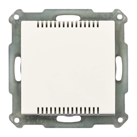
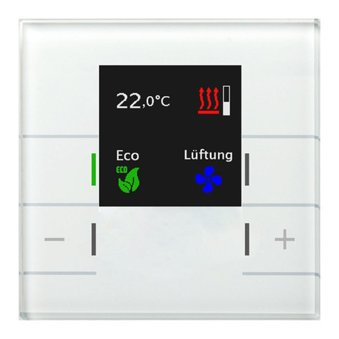
MDT Technologies KNX SCN-LCDGW.01 User manual

MDT technologies GmbH • 51766 Engelskirchen • Papiermühle 1
State 06/2017
Technical Manual
MDT Glass Central Operation Unit
SCN-LCDGW.01
SCN-LCDGS.01

Technical Manual –Glass Central Operation Unit SCN-LCDGx.01
MDT technologies GmbH • 51766 Engelskirchen • Papiermühle 1
2
2
1 Content
1 Content................................................................................................................................................. 2
2 Overview............................................................................................................................................... 6
2.1 Overview Devices .......................................................................................................................... 6
2.2 Usage & Areas of Application........................................................................................................ 6
2.3 Exemplary circuit diagram............................................................................................................. 7
2.4 Design & Usage.............................................................................................................................. 7
2.5 Functions ....................................................................................................................................... 8
2.7. Starting up .................................................................................................................................... 9
3 Communication objects...................................................................................................................... 10
3.1 Summary and Usage.................................................................................................................... 10
3.1.1 LCD-Display........................................................................................................................... 10
3.1.2 Room temperature controller.............................................................................................. 12
3.1.3 Ventilation Control............................................................................................................... 17
3.1.4 Key functions........................................................................................................................ 22
3.1.5 Time switch........................................................................................................................... 25
3.1.6 Logic settings........................................................................................................................ 27
3.2 Default settings of the communication objects .......................................................................... 28
3.2.1 LCD-Display........................................................................................................................... 28
3.2.2 Room Temperature Controller............................................................................................. 28
3.2.3 Ventilation Control............................................................................................................... 30
3.2.4 Key functions........................................................................................................................ 31
3.2.5 Time switch........................................................................................................................... 32
3.2.6 Logic functions...................................................................................................................... 33
4 General settings.................................................................................................................................. 34
5 Settings LCD-Display........................................................................................................................... 35
5.1 General........................................................................................................................................ 35
5.2 LCD-Alarm messages ................................................................................................................... 38
5.3 Display and Operation................................................................................................................. 39
5.3.1 Display in Standby-Mode...................................................................................................... 39
5.3.2 Display of the functional blocks ........................................................................................... 39
5.3.3 Presentation of text messages ............................................................................................. 40

Technical Manual –Glass Central Operation Unit SCN-LCDGx.01
MDT technologies GmbH • 51766 Engelskirchen • Papiermühle 1
3
3
6 Room Temperature Controller........................................................................................................... 41
6.1 Temperature Measurement........................................................................................................ 41
6.2 Alarm/Messages.......................................................................................................................... 43
6.3 Controller general........................................................................................................................ 45
6.3.1 Controller type ..................................................................................................................... 45
6.3.2 Operating modes & Setpoints.............................................................................................. 46
6.3.2.1 Operating mode - Comfort............................................................................................ 47
6.3.2.2 Operating mode - Night................................................................................................. 47
6.3.2.3 Operating mode - Standby ............................................................................................ 47
6.3.2.4 Operating mode - Frost/Heat protection...................................................................... 47
6.3.2.5 Priority of the operating modes.................................................................................... 48
6.3.2.6 Operating mode switchover.......................................................................................... 48
6.3.2.7 Operating mode after reset........................................................................................... 51
6.3.3 Setpoint offset...................................................................................................................... 52
6.3.4 Disable objects ..................................................................................................................... 54
6.3.5 Heating/Cooling request objects.......................................................................................... 55
6.3.6 Guiding ................................................................................................................................. 56
6.3.7 Dead zone............................................................................................................................. 58
6.3.8 Flow temperature limit ........................................................................................................ 60
6.4 Controller setting......................................................................................................................... 61
6.4.1 Control value ........................................................................................................................ 61
6.4.2 PI control continuous ........................................................................................................... 62
6.4.2.1 Max value of control value............................................................................................ 63
6.4.2.2 Heating/ cooling system................................................................................................ 63
6.4.2.3 Proportional range ........................................................................................................ 63
6.4.2.4 Reset time...................................................................................................................... 64
6.4.2.5 Send control value cyclic ............................................................................................... 64
6.4.3 PI control switching (PWM).................................................................................................. 65
6.4.3.1 PWM cycletime.............................................................................................................. 66
6.4.4 Two-step control (switching)................................................................................................ 67
6.4.4.1 Hysteresis ...................................................................................................................... 68
6.4.5 Direction of controller.......................................................................................................... 69
6.4.6 Additional level..................................................................................................................... 69
6.4.7 Additional settings for heating and cooling ......................................................................... 72
4.5.7.1 - 2 Pipe system .............................................................................................................. 72
6.4.7.2 4 Pipe-System ............................................................................................................. 73
6.4.7.3 Switchover heating and cooling .................................................................................... 75
Technical Manual –Glass Central Operation Unit SCN-LCDGx.01
MDT technologies GmbH • 51766 Engelskirchen • Papiermühle 1
4
4
7 Ventilation control.............................................................................................................................. 76
7.1 Step switch bit coded .................................................................................................................. 76
7.1.1 Day/Night switchover........................................................................................................... 77
7.1.2 Type of thresholds: Control value & Delta T ........................................................................ 78
7.1.3 Type of thresholds: Manual control only ............................................................................. 80
7.1.4 Behavior at lock.................................................................................................................... 80
7.1.5 Behavior at Init ..................................................................................................................... 81
7.1.6 Sticking protection................................................................................................................ 81
7.1.7 Priority.................................................................................................................................. 81
7.1.8 Status.................................................................................................................................... 82
7.2 Step Switch –binary coded ......................................................................................................... 82
7.3 Step switch simply....................................................................................................................... 83
7.4 Step switch as Byte...................................................................................................................... 83
7.5 External Control (Slave)............................................................................................................... 84
8 Key functions...................................................................................................................................... 85
8.1 Buttons grouped.......................................................................................................................... 85
8.1.1 Dimming ............................................................................................................................... 86
8.1.2 Shutter.................................................................................................................................. 88
8.1.3 Switch ................................................................................................................................... 89
8.2 Buttons separately ...................................................................................................................... 90
8.2.1 Switch ................................................................................................................................... 90
8.2.1.1 Switch on key press....................................................................................................... 90
8.2.1.2 Toggle on key press ....................................................................................................... 91
8.2.1.3 Send value on key press ................................................................................................ 91
8.2.2 Scene .................................................................................................................................... 92
8.2.3 Switch short/long ................................................................................................................. 94
8.2.4 Toggle Heating/Cooling........................................................................................................ 97

Technical Manual –Glass Central Operation Unit SCN-LCDGx.01
MDT technologies GmbH • 51766 Engelskirchen • Papiermühle 1
5
5
9 Time Switch ........................................................................................................................................ 98
9.1 Time settings ............................................................................................................................... 98
9.2 General time-switch settings..................................................................................................... 100
9.2.1 Call functions of time switch via direct menu .................................................................... 104
9.3 Function settings –Time Switch................................................................................................ 105
9.3.1 Key functions...................................................................................................................... 106
Key function: Send value......................................................................................................... 106
Key function: Dimming............................................................................................................ 111
Key function: Shutter............................................................................................................... 112
Key function: Scene................................................................................................................. 113
9.3.2 Assignment of cycle times.................................................................................................. 114
9.4 Controlling the timer on the device .......................................................................................... 116
10 Logic functions................................................................................................................................ 118
10.1 Behavior after rest................................................................................................................... 118
10.2 Settings Logic A-H.................................................................................................................... 119
10.3 Logic Inputs.......................................................................................................................... 121
11 Index............................................................................................................................................... 122
11.1 List of figures ........................................................................................................................... 122
11.2 List of tables............................................................................................................................. 124
12 Attachment..................................................................................................................................... 127
12.1 Statutory requirements........................................................................................................... 127
12.2 Routine disposal ...................................................................................................................... 127
12.3 Assemblage.............................................................................................................................. 127
12.4 Datasheet ................................................................................................................................ 127

Technical Manual –Glass Central Operation Unit SCN-LCDGx.01
MDT technologies GmbH • 51766 Engelskirchen • Papiermühle 1
6
6
2 Overview
2.1 Overview Devices
The manual refers to the following glass room temperature controller (order number printed in bold
letters):
▪SCN-LCDGW.01 Glass Operation Unit, white
oController type: Two-position, PI, PWM
oconfigurable LCD display with automatic brightness adjustment and adjustable alarm
messages
oventilation control controllable by bit, byte or binary coded
o2 keys configurable
ocan be set as system clock master
oTime Switch with 20 channels, 6 cycle times each channel
o8 logical blocks with 4 inputs
▪SCN- LCDGW S.01 Glass Operation Unit, black
osame function as before
2.2 Usage & Areas of Application
The glass operation unit combines the control of multiple disciplines in a single device. With the glass
control center Timer, ventilation functions, direct functions and room temperature control can be
realized. The device can be controlled via 4 buttons below the LCD display and allows control of the
most important functions even without ETS. In addition, the control panel can be used as a system
clock master.
Two of the four buttons are available to user’s free parameterization; the other two buttons are used
to operate the display. In addition, the screen can show up to 4 alarms that can be triggered via 1-bit
objects, as well as a 14-byte text message.
Up to 20 functions can be connected with up to 6 cycle time in the time switch. All functions, set in
the timer, can be named individually and can be selected directly from the control panel.
Furthermore the timer switch has an astro and a random function.
Also a complete controlling of the room temperature can be realized by the integrated room
temperature controller. The heating as well as the air-conditioning can be controlled.
By using the ventilation control, fan coils and other ventilation devices can be controlled. The
ventilation control can work with a control value as well with temperature difference between
setpoint and current value. Also a manual control is possible.

Technical Manual –Glass Central Operation Unit SCN-LCDGx.01
MDT technologies GmbH • 51766 Engelskirchen • Papiermühle 1
7
7
2.3 Exemplary circuit diagram
Figure 1: Exemplary circuit diagram
2.4 Design & Usage
The following figure provides an overview of the structure and controls:
Figure 2: Design & Usage
1 = Programming button (lateral notch in the housing below the glass)
2 = Button for switching between the functional blocks
3 = Button for specific functions of the function block shown
4 & 5 = Buttons for switching in each functional block
1
2
3
4
5

Technical Manual –Glass Central Operation Unit SCN-LCDGx.01
MDT technologies GmbH • 51766 Engelskirchen • Papiermühle 1
8
8
2.5 Functions
The functions of the glass operation unit are divided into the areas of Time settings, LCD display,
temperature control, ventilation control, time switch and configuration of the keys. In each area, the
following settings can be made:
▪Time settings
In this menu, the time switch can be set as master or as slave and the sending condition of
the time can be set. Furthermore, the location data for the astro function can be made here.
Moreover, a time clock can be set which allows cyclic switching functions.
▪LCD Display
The presentation and the brightness of the display can be set here. Furthermore the
language of the Display and an inverting of the colors can be set here.
▪Temperature Controller
The temperature controller is again divided into the following sub-menus:
oTemperature measurement
In this menu, settings for temperature measurements, such as min / max values and
sensor configurations can be parameterized.
oAlarm/Messages
Alarms / messages, which show falling below or exceeding certain temperatures, can be
set here. Also messages, which are shown at the display, can be set here.
oController general
The desired function (Heating and/or Cooling) are set in this menu. Furthermore the
setpoints and operating modes can be set here.
oController settings
If one type of controller is set, the behavior of the manipulated variable can be set here.
The setting options depend on the used controller.
▪Ventilation Control
The ventilation control allows the control of fans and can be controlled as well manually as
by the current value of the output value or by the difference between setpoint and current
value.
▪Key function of button C/D
The key function can be set as well grouped as separately. As well switching function as
shutter and dimming functions can be used.
▪Functions of time switch
Up to 20 functions can be activated and parameterized further. Furthermore, for each
function up to 6 cycle times can be adjusted.
▪Logic settings
8 logic functions using XOR, AND, OR can be activated and send 1-bit values, 1-byte values or
calling scenes.

Technical Manual –Glass Central Operation Unit SCN-LCDGx.01
MDT technologies GmbH • 51766 Engelskirchen • Papiermühle 1
9
9
2.6. Settings at the ETS-Software
Selection at the product database:
Manufacturer: MDT Technologies
Product family:
Product type: Any
Medium Type: Twisted Pair (TP)
Product name: SCN-LCDGW.01
Order number: SCN-LCDGW.01
2.7. Starting up
After wiring the allocation of the physical address and the parameterization of every channel follow:
(1) Connect the interface with the bus, e.g. MDT USB interface
(2) set bus power up
(3) Press the programming button at the device(red programming LED lights)
(4) Loading of the physical address out of the ETS-Software by using the interface(red LED goes
out, as well this process was completed successful)
(5) Loading of the application, with requested parameterization
(6) If the device is enabled you can test the requested functions(also possible by using the ETS-
Software)

Technical Manual –Glass Central Operation Unit SCN-LCDGx.01
MDT technologies GmbH • 51766 Engelskirchen • Papiermühle 1 • Phone: +49-2263-880 • Fax: +49-2263-4588 • [email protected] • www.mdt.de
10
10
3 Communication objects
3.1 Summary and Usage
3.1.1 LCD-Display
Nr.
Name
Object function
Data type
Direction
Info
Usage
Tip
Objects for LCD-Display:
27
Day/Night
Switching
DPT 1.001
receive
Display responds
to input telegram
Control buttons,
Visu, external
status, Time
Switch
Communication object is
permanently displayed and
used for switching the
backlight of the display
54
Time
Receive status
DPT 10.001
receive
Display responds
to input telegram
Time Switch,
Group
monitor(once),
Visu
Communication object is
permanently displayed and
used to show the right time of
day. Value should be sent
regularly to achieve sufficient
accuracy.
55
Date
Send/Receive state
DPT 11.001
receicve/
send
Master = Time
switch sends date;
Slave = Time
switch receives
date
Time switch,
group monitor
(once), Visu
Communication object is
always shown and
sends/receive the date

Technical Manual –Glass Central Operation Unit SCN-LCDGx.01
MDT technologies GmbH • 51766 Engelskirchen • Papiermühle 1 • Phone: +49-2263-880 • Fax: +49-2263-4588 • [email protected] • www.mdt.de
11
11
56
Date and Time
Send/Receive state
DPT 19.001
receicve/
send
Master = Time
switch sends time
and date;
Slave = Time
switch receives
time and date
Time switch,
group monitor
(once), Visu
Communication object is
always shown and
sends/receive the time and
date
57-
60
Message 1-4
Alarm input fort text
message
DPT 1.001
receive
Display responds
to input telegram
Status objects,
Alarm objects…
Communication object will
appear if alarms are activated
in the Alarms menu. By
receiving a 1, the set message
is shown on the display
61
Message 14 Byte
Variable text message
DPT 16.000
receive
Display responds
to input telegram
Visu, Control unit,
Tableau
Communication object is
displayed as soon as this
alarms / messages is enabled
in the menu; can display
arbitrary string.
Table 1: Overview objects - LCD Display

Technical Manual –Glass Central Operation Unit SCN-LCDGx.01
MDT technologies GmbH • 51766 Engelskirchen • Papiermühle 1 • Phone: +49-2263-880 • Fax: +49-2263-4588 • [email protected] • www.mdt.de
12
12
3.1.2 Room temperature controller
Nr.
Name
Object function
Data type
Direction
Info
Usage
Tip
Objects for room temperature controller:
0
Actual temperature
value
Transmit temperature
value
DPT 9.001
send
Controller sends
current
temperature
Visu, Display,
Diagnostic,…
Communication object is
shown permanent and sends
according to the setting its
current value or can only be
read via the bus
1
max. temperature
Exceeded value
DPT 1.001
send
Controller sends
state
Visu, Display,
Diagnostic,…
Communication object is
shown when messages are
active
2
min. temperature
Below the value
DPT 1.001
send
Controller sends
state
Visu, Display,
Diagnostic,…
Communication object is
shown when messages are
active
3
Frost alarm
Send alarm
DPT 1.001
send
Controller sends
state
Visu, Display,
Diagnostic,
Additional stage,…
Communication object is
shown when alarms are active

Technical Manual –Glass Central Operation Unit SCN-LCDGx.01
MDT technologies GmbH • 51766 Engelskirchen • Papiermühle 1 • Phone: +49-2263-880 • Fax: +49-2263-4588 • [email protected] • www.mdt.de
13
13
4
Heat alarm
Send alarm
DPT 1.001
send
Controller sends
state
Visu, Display,
Diagnostic,
Additional stage,…
Communication object is
shown when alarms are active
5
External sensor
Read external sensor
DPT 9.001
receive
Controller receives
external
temperature
Input for external
temperature
Communication object is
shown when sensor is set to at
least 10% external sensor
6
Setpoint comfort
Set setpoint
DPT 9.001
receive
Controller receives
new absolute
setpoint
Visu, Opereating
keys, Control unit
Object is permanent shown
when the controller is active. A
new setpoint can be set via this
object.
7
Manual setpoint value
offset
Reduction/Increase
DPT 9.002
receive
Controller receives
new setpoint
offset
Visu, Display,
Operating keys,
Control unit
Object is shown when the
setpoint offset via 2 Byte
object is active. The setpoint is
shifted according to the
current setpoint.
8
Control value heating
Send control value
DPT 1.001/
DPT 5.001
send
Controller sends
manipulated value
Heating actuator,
actuators
Object is shown when the
controller is set to heating. The
DPT depends to the controller
type (two-level & PWM –
DPT1.001, PI-DPT5.001).

Technical Manual –Glass Central Operation Unit SCN-LCDGx.01
MDT technologies GmbH • 51766 Engelskirchen • Papiermühle 1 • Phone: +49-2263-880 • Fax: +49-2263-4588 • [email protected] • www.mdt.de
14
14
8
Control value
heating/cooling
Send control value
DPT 1.001/
DPT 5.001
send
Controller sends
manipulated value
Heating actuator,
actuators
Object is shown when the
controller is set to heating and
cooling. The DPT depends to
the controller type (two-level
& PWM –DPT1.001, PI-
DPT5.001).
9
Control value additional
heating
Send control value
DPT 1.001
send
Controller sends
manipulated value
Heating actuator,
actuators
Object is shown when the
controller is set to heating and
an additional stage is activated.
The DPT depends to the
adjusted controller type (two-
level & PWM –DPT1.001, PI-
DPT5.001).
10
Control value cooling
Send control value
DPT 1.001/
DPT 5.001
send
Controller sends
manipulated value
Heating actuator,
actuators
Object is shown when the
controller is set to cooling. The
DPT depends to the controller
type (two-level & PWM –
DPT1.001, PI-DPT5.001).
11
Mode comfort
Switch mode
DPT 1.001
receive
Controller
switches mode
Visu, Opereating
keys, Control unit
Object is always shown and
switches the operating modes
according to the adjusted
priority.
12
Mode Night
Switch mode
DPT 1.001
receive
Controller
switches mode
Visu, Opereating
keys, Control unit
Object is always shown and
switches the operating modes
according to the adjusted
priority.
13
Mode Frost/Heat
protection
Switch mode
DPT 1.001
receive
Controller
switches mode
Visu, Opereating
keys, Control unit
Wird standardmäßig
eingeblendet. Betriebsart
schaltet in Abhängigkeit der
eingestellten Priorität.

Technical Manual –Glass Central Operation Unit SCN-LCDGx.01
MDT technologies GmbH • 51766 Engelskirchen • Papiermühle 1 • Phone: +49-2263-880 • Fax: +49-2263-4588 • [email protected] • www.mdt.de
15
15
14
Heating disable object
Disable heating
DPT 1.003
recieve
Controller
diasables heating
Visu, Opereating
keys, Control unit
Can be activated in the settings
when the controller is set to
heating.
15
Cooling disable object
Disable cooling
DPT 1.003
recieve
Controller
diasables cooling
Visu, Opereating
keys, Control unit
Can be activated in the settings
when the controller is set to
cooling.
17
Heating request
Send request
DPT 1.001
send
Controller sends
heating request
Actuator for
switching the
heating pump…
Can be activated in the settings
when the controller is set to
heating.
18
Cooling request
Send request
DPT 1.001
send
Controller sends
cooling request
Actuator for
switching the
cooling pump…
Can be activated in the settings
when the controller is set to
cooling.
19
Heating/Cooling
switchover
0 = cooling, 1 = heating
DPT 1.001
receive
Controller
switches between
heating and
cooling
Visu, Opereating
keys, Control unit
Can be activated in the
parameter when the controller
is set to heating and cooling.
20
Outside temperature
Read external sensor
DPT 9.001
receive
Controller receives
temperature from
outside sensor
Outdoor
temperature
sensor
Object is shown when the
guiding is activated in the
parameter
21
Max memory value
Read memory
DPT 9.001
send
Controller sends
max. temperature
Visu, Display,
Diagnostic…
Object is shown when the
min/max values are activated
22
Min memory value
Read memory
DPT 9.001
send
Controller sends
min. temperature
Visu, Display,
Diagnostic…
Object is shown when the
min/max values are activated
23
Min/Max Memory Reset
Reset memory
DPT 1.001
receive
Controller resets
min/max values
Visu, Opereating
keys, Control unit
Object is shown when the
min/max values are activated

Technical Manual –Glass Central Operation Unit SCN-LCDGx.01
MDT technologies GmbH • 51766 Engelskirchen • Papiermühle 1 • Phone: +49-2263-880 • Fax: +49-2263-4588 • [email protected] • www.mdt.de
16
16
24
Reset setpoint value
Parameter read in
DPT 1.001
receive
Controller resets
the setpoints to
the values which
are set in the
parameter
Visu, Opereating
keys, Control unit
Object is always shown when
the controller is active
25
DPT_HVAC Status
Send controller status
-
send
Controller sends
current state
Visu, Display,
Diagnostic,…
Object is always shown when
the controller is active
28
Error external sensor
Error message
DPT 1.001
send
Controller sends
state
Visu, Display,
Diagnostic,…
Object is always shown when
the controller is active
29
Actual setpoint
Send setpoint
DPT 9.001
send
Conntroller sends
current setpoint at
a read request
Visu, Display,
Diagnostic,…
Object is always shown when
the controller is active
30
RHCC Status
Send controller status
DPT 22.101
send
Controller sends
current state
Visu, Display,
Diagnostic,…
Object is always shown when
the controller is active
31
Mode selection
Select mode
DPT 20.102
receive/
send
Controller
switches between
operating modes
and sends the
current operating
mode if activated
Visu, Operating
keys, Control unit,
Display,
Diagnostic, …
Communication object is
permanently displayed when
the controller was activated.
Via the parameter “Send status
on object 31 mode selection”,
the sending of this object can
be activated. So this object can
be directly used by home
servers and visualizations.

Technical Manual –Glass Central Operation Unit SCN-LCDGx.01
MDT technologies GmbH • 51766 Engelskirchen • Papiermühle 1 • Phone: +49-2263-880 • Fax: +49-2263-4588 • [email protected] • www.mdt.de
17
17
32
Manual setpoint value
offset
Increase/Reduction
(1 = + adjusted step,
0 = - adjusted step)
DPT 1.001
receive
Controller receives
setpoint value
offset via a 1 Bit
object
Visu, Operating
keys, Control unit,
Display,
Diagnostic, …
Object is shown when
parameter “Setpoint value
offset via” is set to 1 Bit object
and shifts the set value
depending on the current
setpoint. The amount of
displacement can be set in the
parameters.
33
Flow temperature
Read external sensor
DPT 9.001
receive
Controller receives
temperature from
external sensor
external
temperature
sensor
Object is shown when the
limitation of flow temperature
is activated.
Table 2: Overview communication objects - Room Temperature Controller
3.1.3 Ventilation Control
Nr.
Name
Object function
Data type
Direction
Info
Usage
Tip
Objects for Ventilation Control:
38
Ventilation Control
Block
DPT 1.003
receive
Controller locks
ventilation control
Visu, Operating
keys, Control unit,
Display, …
Object is only shown when the
locking function was activated
in the settings
39
Ventilation Control
Level 1
DPT 1.001
send
Controller
switches level 1
Actuator for
controlling a
ventilation
system, Fan-Coil
actuator
Object is shown at the setting
step switch bit coded

Technical Manual –Glass Central Operation Unit SCN-LCDGx.01
MDT technologies GmbH • 51766 Engelskirchen • Papiermühle 1 • Phone: +49-2263-880 • Fax: +49-2263-4588 • [email protected] • www.mdt.de
18
18
39
Ventilation Control
Bit 0
DPT 1.002
send
Controller
switches Bit 0
Actuator for
controlling a
ventilation
system, Fan-Coil
actuator
Object is shown at the setting
step switch binary coded

Technical Manual –Glass Central Operation Unit SCN-LCDGx.01
MDT technologies GmbH • 51766 Engelskirchen • Papiermühle 1 • Phone: +49-2263-880 • Fax: +49-2263-4588 • [email protected] • www.mdt.de
19
19
40
Ventilation Control
Level 2
DPT 1.001
send
Controller
switches level 2
Actuator for
controlling a
ventilation
system, Fan-Coil
actuator
Object is shown at the setting
step switch bit coded
40
Ventilation Control
Bit 1
DPT 1.002
send
Controller
switches Bit 1
Actuator for
controlling a
ventilation
system, Fan-Coil
actuator
Object is shown at the setting
step switch binary coded
39
Ventilation Control
Level 1+2
DPT 1.001
send
Controller
switches level 1
und 2
Actuator for
controlling a
ventilation
system, Fan-Coil
actuator
Object is shown at the setting
step switch simply
41
Ventilation Control
Level 3
DPT 1.001
send
Controller
switches level 3
Actuator for
controlling a
ventilation
system, Fan-Coil
actuator
Object is shown at the setting
step switch bit coded
41
Ventilation Control
Bit 2
DPT 1.002
send
Controller
switches Bit 2
Actuator for
controlling a
ventilation
system, Fan-Coil
actuator
Object is shown at the setting
step switch binary coded
41
Ventilation Control
Level 1+2+3
DPT 1.001
send
Controller
switches level 1, 2
und 3
Actuator for
controlling a
ventilation
system, Fan-Coil
actuator
Object is shown at the setting
step switch simply

Technical Manual –Glass Central Operation Unit SCN-LCDGx.01
MDT technologies GmbH • 51766 Engelskirchen • Papiermühle 1 • Phone: +49-2263-880 • Fax: +49-2263-4588 • [email protected] • www.mdt.de
20
20
42
Ventilation Control
Level 4
DPT 1.001
send
Controller
switches level 4
Actuator for
controlling a
ventilation
system, Fan-Coil
actuator
Object is shown at the setting
step switch bit coded
42
Ventilation Control
Level 1+2+3+4
DPT 1.001
send
Controller
switches level 1, 2,
3 und 4
Actuator for
controlling a
ventilation
system, Fan-Coil
actuator
Object is shown at the setting
step switch simply
43
Ventilation Control
1 Byte Status ventilation
level
DPT 5.010
send
Controller sends
current status
Visu, Operating
keys, Control unit,
Display, …
Object must be activated in the
settings by the parameter “Use
status object 43 as”. Object
sends the current level: Value 1
= Level 1, Value 2 = Level 2…
43
Ventilation Control
Status for ventilation
active
DPT 1.001
send
Controller sends
current status
Visu, Operating
keys, Control unit,
Display, …
Object must be activated in the
settings by the parameter “Use
status object 43 as”. Object
sends whether the ventilation
is active or not.
44
Ventilation Control
Control value
DPT 5.001
send
Controller sends
manipulated value
Actuator for
controlling a
ventilation
system, Fan-Coil
actuator
Object is shown at the setting
„Step switch as Byte“
45
Ventilation Control
Object priority
DPT 1.001
receive
Controller receives
incoming telegram
Visu, Operating
keys, Control unit,
Display, …
Object must be activated in the
settings and can call several
states.
This manual suits for next models
1
Table of contents
Other MDT Technologies Controllers manuals

MDT Technologies
MDT Technologies AKH-0400.01 User manual

MDT Technologies
MDT Technologies AKU-0816.01 User manual

MDT Technologies
MDT Technologies AKK UP Series User manual

MDT Technologies
MDT Technologies JAL-01UP.02 User manual

MDT Technologies
MDT Technologies BE-GT2TW.01 User manual

MDT Technologies
MDT Technologies JAL-0206.01 User manual

MDT Technologies
MDT Technologies RF-TA55A2.01 User manual

MDT Technologies
MDT Technologies AKH-0400.01 User manual

MDT Technologies
MDT Technologies SCN-RT1UP.01 User manual

MDT Technologies
MDT Technologies AMI-0416.03 User manual