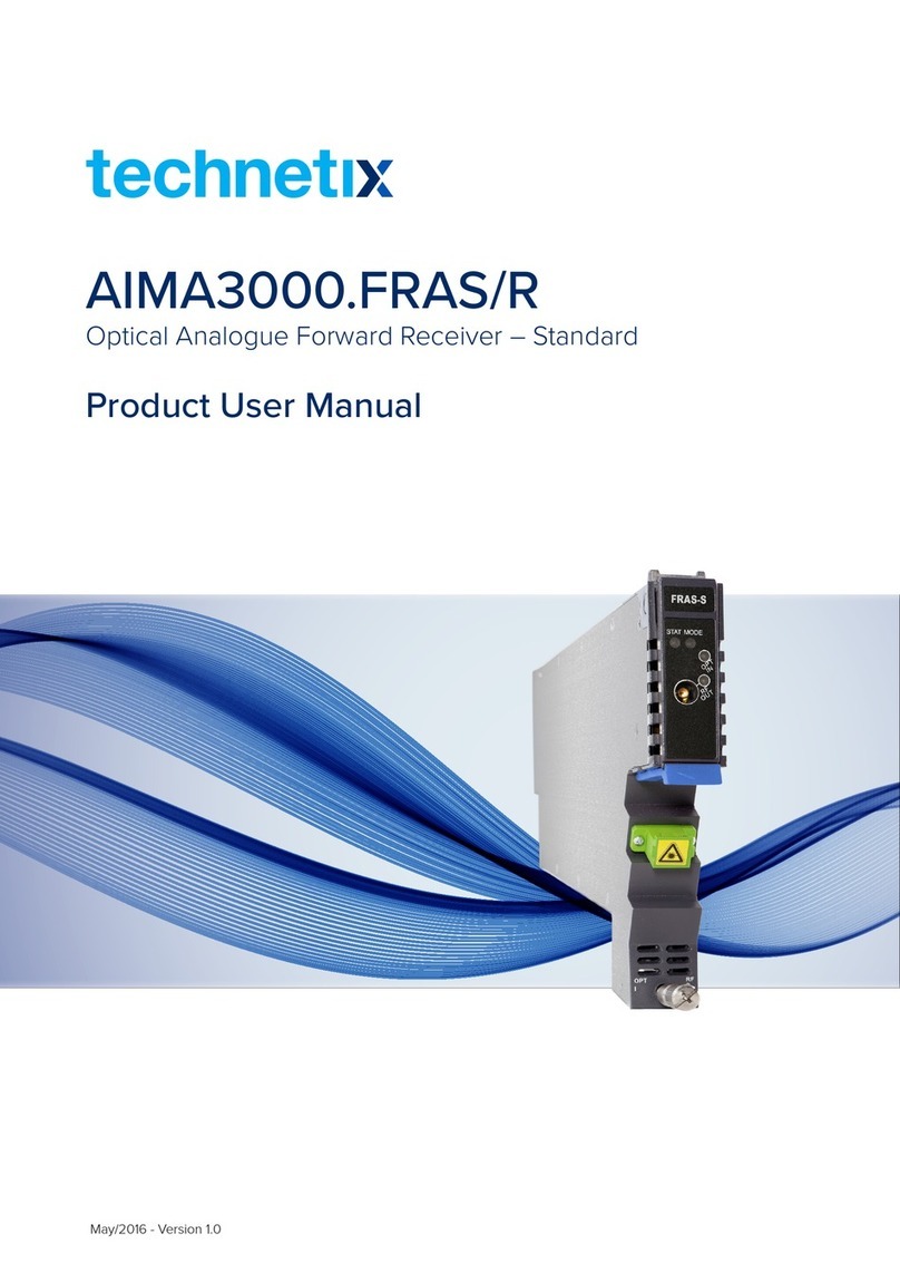
technetix AIMA3000 User manual

AIMA3000.RRAS-G-R
Online
Email: customer.service.[email protected]
Website: technetix.com
Jan/2018 - EU - V2
User Manual

AIMA3000.RRAS/G/R Product User Manual
Technetix Group Limited
AIMA3000.RRAS/G/R
Analogue Return Receiver Series
Product User Manual

AIMA3000.RRAS/G/R Product User Manual
Technetix Group Limited
Contents
1 About This Manual ....................................................................................................................................................5
1.1 Related Documentation........................................................................................................................................................................5
1.2 Technical Support...................................................................................................................................................................................5
2 Precautions.................................................................................................................................................................6
3 Overview.....................................................................................................................................................................7
3.1 RRAS Overview .......................................................................................................................................................................................7
3.1.1 About the RRAS..............................................................................................................................................................................7
3.1.2 Features for the RRAS..................................................................................................................................................................8
3.1.3 Order Details for RRAS ................................................................................................................................................................8
3.1.4 Specifications for the RRAS........................................................................................................................................................9
3.1.5 Block Diagram for RRAS..............................................................................................................................................................10
3.2 RRAG Overview.......................................................................................................................................................................................11
3.2.1 About the RRAG.............................................................................................................................................................................11
3.2.2 Features for the RRAG .................................................................................................................................................................12
3.2.3 Order details for RRAG ................................................................................................................................................................12
3.2.4 Specifications for the RRAG .......................................................................................................................................................13
3.2.5 Block Diagram for RRAG .............................................................................................................................................................14
3.3 RRAR Overview .......................................................................................................................................................................................15
3.3.1 About the RRAR .............................................................................................................................................................................15
3.3.2 Features for the RRAR..................................................................................................................................................................16
3.3.3 Order Details for RRAR ................................................................................................................................................................16
3.3.4 Specifications for the RRAR........................................................................................................................................................17
3.3.5 Block Diagram for RRAR..............................................................................................................................................................18
4 Functional Overview.................................................................................................................................................19
4.1 Automatic Gain Control.........................................................................................................................................................................19
4.2 Manual Gain Control..............................................................................................................................................................................19
4.3 Output Level Control Chart for RRAS...............................................................................................................................................19
4.4 Output Level Control Chart for RRAG ..............................................................................................................................................20
4.5 FBC Function Description (Only for RRAS-Q-M) ...........................................................................................................................21
4.6 Hot-Swap Function Overview.............................................................................................................................................................23
5 Module details ...........................................................................................................................................................24
5.1 Front Panel and Rear Panel View......................................................................................................................................................24
5.1.1 Front Panel View............................................................................................................................................................................25
5.1.2 Rear Panel View.............................................................................................................................................................................26
6 Installation ..................................................................................................................................................................27
6.1 Preparatory Work for Installation .......................................................................................................................................................27
6.2 Unpacking.................................................................................................................................................................................................27

AIMA3000.RRAS/G/R Product User Manual
Technetix Group Limited
6.3 Power and Cooling Requirements....................................................................................................................................................27
6.4 Module Installation .................................................................................................................................................................................28
6.4.1 Checking the optical input-signal level ..................................................................................................................................29
6.5 Connecting the optical cables ..................................................................................................................................................29
6.5.1 Using the Sliding Fibre Guide....................................................................................................................................................29
6.5.2 Using the Fibre Tray......................................................................................................................................................................32
6.5.3 Cleaning the Fibre Connector Ends and the Front-panel Optical Ports......................................................................34
6.5.4 Connecting the Optical Fibres ..................................................................................................................................................35
6.6 Connecting RF cables...........................................................................................................................................................................35
6.7 Redundancy Connection (for RRAR only) .......................................................................................................................................36
6.8 Power-on testing.....................................................................................................................................................................................36
6.9 Module Removal .....................................................................................................................................................................................37
7 Module Configuration & Alarms .............................................................................................................................38
7.1 Port configuration ...................................................................................................................................................................................38
7.2 Setting up the RF Input level...............................................................................................................................................................39
7.3 Factory Default Settings .......................................................................................................................................................................41
7.4 Reboot RRAS / RRAG Module.............................................................................................................................................................42
7.5 Upgrade RRAS / RRAG Firmware ......................................................................................................................................................43
7.6 Hot-swap Configuration........................................................................................................................................................................44
7.7 Backup and Restore Feature..............................................................................................................................................................45
7.8 Alarm Monitoring.....................................................................................................................................................................................46
7.8.1 Alarm Status Pages .......................................................................................................................................................................46
7.8.2 Alarm Settings Configuration.....................................................................................................................................................49
7.8.3 LED Status Indicators....................................................................................................................................................................52
7.9 Log Management....................................................................................................................................................................................54
7.10 Port Configuration...................................................................................................................................................................................55
7.10.1 Using the Port Configuration Page ..........................................................................................................................................55
7.10.2 Optical Input Port Signal..............................................................................................................................................................57
7.10.3 RF Configuration ............................................................................................................................................................................58
7.11 Redundancy Configuration and Alarms (for RRAR only) ............................................................................................................59
8 Module Application...................................................................................................................................................61
8.1 RRAS NPR Curve.....................................................................................................................................................................................61
8.2 RRAG NPR Curve....................................................................................................................................................................................61
9 Common Faults..........................................................................................................................................................62
9.1 Status LED Fault Indications................................................................................................................................................................62
9.2 Common Faults – Resultant LED Status..........................................................................................................................................62
9.3 Other Faults..............................................................................................................................................................................................63
10 Declaration of Conformity .......................................................................................................................................64

AIMA3000.RRAS/G/R Product User Manual
Technetix Group Limited
1 About This Manual
1.1 Related Documentation
The following documents may be used in conjunction with this manual:
■ Technetix.AIMA3000 - Product User Manual
■ Technetix.AIMA ASMM - Product User Manual
■ AIMA3000 NMS Web Management System Product User Manual
■ Technetix.NMS3-EPSM - Basic Inventory Management
■ Technetix.NMS3-EPSM - Basic Alarm Management
■ Technetix.NMS3-EPSM - Basic System Management
■ Technetix.NMS3-EPSM - Basic Template Management
1.2 Technical Support
If you need help in the process of setting up and maintaining an RRAS/G/R, please contact Technetix technical
support sta:
Europe:
Technetix BV
Kazemat 5
NL-3905 NR Veenendaal
P.O. Box 385
NL-3900 AJ Veenendaal
The Netherlands
Phone: +31 318 58 59 59
Email: customer.service.[email protected]

AIMA3000.RRAS/G/R Product User Manual
Technetix Group Limited
2 Precautions
WARNING!
This equipment is intended for indoor applications. To prevent fire or electrical shock, or
damage to the equipment, do not expose units to water or moisture.
■ You should carefully read and thoroughly understand the contents of the manual before .
installing and using this equipment.
■ A typical connector is the SC/APC 8°. Note: An 8 ° angle polished optical connectors must
be used.
■ At any time, there may be dangerous voltage inside the device.
■ Do not power up before the cover and the panels of the equipment are installed and the
enclosure is closed
Cleaning
Only use a damp cloth for cleaning the front panel. Use a soft dry cloth to clean the top of the unit.
DO NOT use any spray cleaners or chemicals of any kind.
Outage or overload requiring service and repairs
Unplug the unit and refer the servicing to Technetix qualified service personnel only.
Servicing and repairs
DO NOT attempt to service this unit yourself. Refer all servicing needs to Technetix qualified service
personnel only.
WARNING!
Exposure to class 1M laser radiation is possible. Access should be restricted to
trained personnel only. Do not view exposed fibre or connector ends when handling
optical equipment.

AIMA3000.RRAS/G/R Product User Manual
Technetix Group Limited
3 Overview
3.1 RRAS Overview
3.1.1 About the RRAS
The Technetix AIMA3000 RRAS series Analogue Return Receiver - Standard is designed for multi-services operators to
increase network-return capacities for the ever-growing demand for bandwidth, while minimising physical headend space
and power usage.
With the optional embedded Full Band Capture (FBC) module, it enables the operator to capture and monitor the return
path spectrum helping the operator to quickly find and locate the upstream noise and the related upstream signal levels.
Advanced spectrum analysing software is available as in a standalone version or as module within Technetix NMSE
Software suite. It also can be easily integrated into operators exist network management system.
Next to above mentioned online management and controlling capabilities the can also be conveniently monitored and
controlled through a computer directly connected to one of the Ethernet ports of the ASMM module.
All module settings are retained in non-volatile memory to ensure trouble-free operation. Bulk updating, automatic
uploading and downloading of configuration files is possible using Technetix NMSE web-based management system.

AIMA3000.RRAS/G/R Product User Manual
Technetix Group Limited
3.1.2 Features for the RRAS
■ Bandwidth 5 ~ 204 MHz to meet EuroDOCSIS and DOCSIS 3.0 / 3.1 frequency band requirements
■ RF output 48 dBmV with a -6 dBm optical input and an OMI of 6%
■ Wide band receiver (1260~1620nm) to suit CWDM and DWDM applications
■ Allows up to 64 receivers (4x16 Modules) in only 4 RU of space
■ User-selectable MGC or AGC
■ Easy to install due to RF-Paddle board backplane design
■ Plug-and-play and hot-swappable
■ Dedicated testport per return channel
■ Full Band Capture oers automated and 7*24 return path/upstream RF and data performance monitoring and analysis
■ Help operators pre-emptively identify and address spectrum variances
■ Lower capital expenses by eliminating the need for expensive test equipment
■ Web-browser access eliminates the need for a thick client and a mobile APP is available
■ An intuitive user interface similar as meter adapt to user’s operating habits
■ Improve network maintenance eciency and Increase customer satisfaction
■ FBC software which can work independently, in Technetix NMSE or be integrated into third-party systems
■ FCC, CE and RCM (1) compliant
(1) See Declaration of Conformity for current status.
3.1.3 Order Details for RRAS
A-RRAS–[W]-[X]-[Y]-[Z] Analogue Return Receiver - Standard
Options:
W Optical ports
Q Quad (4)
XFBC function (1)
M With FBC Management
Y Optical Connector Type
S SC/APC (2)
E E2000/APC
F FC/APC
L LC/APC
Z Bandwidth
20 5~204 MHz (Standard)
(1) Option for FBC Management configurations only, if not used omit X when making an order.
(2) Standard option. Contact a Technetix Sales Representative for availability of other options.

AIMA3000.RRAS/G/R Product User Manual
Technetix Group Limited
3.1.4 Specifications for the RRAS
Optical Performance
Optical wavelength 1260 ~ 1620 nm
Optical inputs -18 ~ +2 dBm
Optical return loss > 50 dB
Optical connectors 4 x SC/APC (1), FC/APC, LC/APC, E2000/APC
RF Performance
RF bandwidth 5 ~ 204 MHz
RF output level (2) 48 dBmV
RF flatness ± 0.75 dB (5 ~ 204 MHz)
Gain adjustment 0 ~ 52 dB in 0.5 dB increments (default 42 dB)
RF impedance 75 Ω
RF return loss > 16 dB
Receiver isolation > 60 dB
RF test point relative to RF -20 ±1 dB
Output port
RF connectors 4 x GSK-type female
RF test points 4 x Mini-SMB
Alarms and status Front-panel LEDs, SNMP Traps
Notes:
(1) Standard option. Contact a Technetix Sales Representative for availability of other options.
(2) Measured in a typical system with -6 dBm optical input, 6 % OMI, gain setting adjusted to maximum
(the stated RF output level does not necessarily apply with other optical input levels). dBuV= 60 + dBmV.
Link Performance
CNR (3) > 48 dB
IMD2 (4) < -52 dBc
NPR (5) > 35 dB
(over dynamic range of 15 dB)
Notes:
(3) Measured @ -2 dBm ,6% OMI, 4 Channels
(4) RRAS: Measured in a typical system with Technetix ODN4P-RT, 4 channels, (11.5 MHz, 26.5 MHz, 45.5 MHz, and 58.5 MHz), 0 dBm, 6 % OMI. IMD2 is
measured at f1 ± f2.
(5) RRAS: Measured in a typical system with Technetix ODN4P-RT, 10 km single mode optical fibre using 35 MHz noise loading.

AIMA3000.RRAS/G/R Product User Manual
Technetix Group Limited
General
Power supply Powered via AIMA3000 backplane
Power consumption < 8.5 W
Operating temperature -5 ~ +55 °C
Storage temperature -25 ~ +70 °C
Operating/storage humidity Max. 90% RH (non-condensing)
Dimensions (W*D*H) 24.6 * 410 * 152.5 mm
Weight 0.95 kg
Network management Technetix NMSE or through ASMM’s Web Interface
With the FBC module
Frequency Capture 5 to 204 MHz
Dynamic range 60 dB
Spectrum Lines 3, including live, max hold and min hold
RBW UP from 30 KHz
VBW Auto adaptable
Vertical Markers 2
3.1.5 Block Diagram for RRAS

AIMA3000.RRAS/G/R Product User Manual
Technetix Group Limited
3.2 RRAG Overview
3.2.1 About the RRAG
The Technetix AIMA3000 RRAG series Analogue Return Receiver- RFoG are designed for multi-service operators to
increase network return capacity and meet an ever-growing demand for bandwidth, while minimising physical headend
space and increasing power eciency.
The RRAG is designed to plug into Technetix latest generation Advanced Intelligent Multi-Service Headend Platform
(AIMA3000). The RRAG is specially designed to accommodate low power optical input as low as -28 dBm. The RRAG
incorporates four independent optical return-path receivers that operate at wavelengths between 1260-1620 nm. The
design allows up to 64 independent receivers in 4 RU of space. The user can set each receiver individually for manual
gain control (MGC) mode. The unit has a low noise profile and high-performance amplifiers to ensure good signal-to-noise
ratio as well as low distortion characteristics. The RRAG is compatible with RFoG ONU (R-ONU) as well as Technetix micro
nodes DPON. With versatile RF outputs, the RRAG is flexible for various headend configurations.
The RRAG can also be conveniently monitored and controlled through a computer connected to one of the Ethernet ports
via the ASMM module. All module settings are retained in non-volatile memory to ensure trouble-free operation. Bulk
updating is possible using Technetix NMSE web-based management system.

AIMA3000.RRAS/G/R Product User Manual
Technetix Group Limited
3.2.2 Features for the RRAG
■ Upstream bandwidth 5 - 85 MHz with DOCSIS 3.0 support
■ RF output 48 dBmV with a -20 dBm optical input and an OMI of 10%
■ 1260 - 1620 nm operating wavelength, to suit CWDM, DWDM, and RFoG applications
■ Wide optical input from -28 dBm to -12 dBm
■ 19-inch 4RU chassis supports up to 16 Application Modules
■ A single RRAG module has 4 optical inputs; a full chassis supports up to 64 channels
■ Real-time alarm monitoring
■ Remote firmware upgrade and auto upload/download of configuration files through ASMM web interface or
using Technetix NMSE
■ Plug-and-play hot-swappable
■ Easy to install, with blind mate RF connectors
■ Independent RF test points for ease of setup and maintenance
■ A single receiver consumes less than 2 W of power
■ FCC, CE and RCM (1) compliant
(1) See Declaration of Conformity for current status.
3.2.3 Order details for RRAG
A-RRAG–[X]-[Y]-[Z] Analogue Return Receiver - RFoG
Options:
W Optical ports
Q Quad (4)
Y Optical Connector Type
S SC/APC *
E E2000/APC
F FC/APC
L LC/APC
Z Bandwidth
20 5~85 MHz (Standard)
* Option for FBC Management configurations only, if not used omit X when making an order.

AIMA3000.RRAS/G/R Product User Manual
Technetix Group Limited
3.2.4 Specifications for the RRAG
Optical Performance
Optical wavelength 1260 ~ 1620 nm
Optical inputs -28 ~ -12 dBm
Optical return loss >50 dB
Optical connectors 4 x SC/APC (1), FC/APC, LC/APC, E2000/APC
RF Performance
RF bandwidth 5 ~ 85 MHz
RF output level (2) 48 dBmV (108 dBuV) @-20 dBm optical input 10% OMI, full gain.
RF flatness ± 0.75 dB
Gain range 42 ~ 52 dB in 0.5 dB increments
RF impedance 75 Ω
RF return loss > 16 dB
Receiver isolation > 55 dB
RF test point relative to -20 ±1 dB
RF output port
RF connectors 4 x GSK-type female
RF test points 4 x Mini-SMB
Alarms and status Front-panel LEDs, SNMP Traps
Equivalent Input 4 pA/sqr(Hz)
Noise Current
Link Performance
CNR (2) > 38 dB
IMD2 (2) < -47 dBc
NPR (@ -22 dBm) > 30 dB (over 10 dB dynamic range)
General
Power supply Powered via AIMA3000 backplane
Power consumption < 8.0 W
Operating temperature 0 ~ +55 °C
Storage temperature -20 ~ +70 °C
Operating/storage humidity Max. 90% RH (non-condensing)
Dimensions (W*D*H) 24.6 * 410 * 152.5 mm
Weight 0.87 kg
Network management Technetix NMSE or through ASMM’s Web Interface
Notes:
(1) Standard option. Contact a Technetix Sales Representative for availability of other options.
(2) Measured in a typical system with a -20 dBm optical input, an OMI of 10%, and gain set to maximum (the stated RF output level may dier with other
optical input levels). And dBuV= 60 + dBmV.

AIMA3000.RRAS/G/R Product User Manual
Technetix Group Limited
3.2.5 Block Diagram for RRAG

AIMA3000.RRAS/G/R Product User Manual
Technetix Group Limited
3.3 RRAR Overview
3.3.1 About the RRAR
The Technetix AIMA3000 RRAR series Analogue Return Receiver - Redundant (RRAR) are designed for multi-services
operators to increase network-return capacities for the ever-growing demand for data and voice bandwidth, while
minimizing physical headend space and power requirements.
The RRAR, is designed to plug into Technetix latest generation Advanced Intelligent Multi- Service Headend Platform
(AIMA3000). The RRAR incorporates four independent optical return-path receivers that can operate at any wavelength
between 1260~1620 nm. This density allows up to 64 independent receivers in only 4 RU of space. The user can set
each receiver individually for operation in either manual gain control (MGC) mode or automatic gain control (AGC) mode
based on optical input power. The unit has a low-noise profile and high performance amplifiers to ensure a good signal-
to-noise ratio as well as low distortion characteristics. The RRAR is compatible with Technetix existing optical nodes
including the ODN1P, ODN2P, ODN4P, and ODN2000. With high RF outputs, the RRAR can be adapted to work with
various headend configurations.
The RRAR can also be conveniently monitored and controlled through a computer connected to one of the Ethernet ports
via the ASMM module.
All module settings are retained in non-volatile memory to ensure trouble-free operation. Bulk updating, automatic
uploading and downloading of configuration files is possible using Technetix NMSE web-based management system.

AIMA3000.RRAS/G/R Product User Manual
Technetix Group Limited
3.3.2 Features for the RRAR
■ Bandwidth 5 ~ 204 MHz to meet EuroDOCSIS and DOCSIS 3.1 frequency band requirements
■ RF output 48 dBmV with a -6 dBm optical input and an OMI of 6%
■ Operates between 1260 ~ 1620 nm wavelength, to suit CWDM and DWDM applications
■ 19-inch 4RU chassis supports up to 16 Application Modules
■ A single RRAR module has 4 optical inputs; the full chassis supports up to 64 channels
■ User-selectable MGC or AGC
■ Real-time alarm monitoring
■ Remote firmware upgrade and auto upload/download of configuration files through ASMM web interface or
using Technetix NMSE
■ Plug-and-play and hot-swappable
■ Easy to install, with blind mate RF connectors
■ Independent RF test points for ease of setup and maintenance
■ A single receiver consumes less than 3 W of power
■ Fully FCC, CE, and RCM compliant
3.3.3 Order Details for RRAR
A-RRAR–[X]-[Y]-[Z] Analogue Return Receiver - Redundant
Options:
W Optical ports
Q Quad (4)
Y Optical Connector Type
S SC/APC (1)
E E2000/APC
F FC/APC
L LC/APC
Z Bandwidth
20 5~204 MHz (Standard)
(1) Option for FBC Management configurations only, if not used omit X when making an order.

AIMA3000.RRAS/G/R Product User Manual
Technetix Group Limited
3.3.4 Specifications for the RRAR
Optical Performance
Optical wavelength 1260 ~ 1620 nm
Optical inputs -20 ~ +2 dBm
Optical return loss > 55 dB
Optical connectors 4 x SC/APC (1), FC/APC, LC/APC, E2000/APC
RF Performance
RF bandwidth 5 ~ 204 MHz
RF output level (2) 35 dBmV per channel (Full Gain)
RF flatness ±0.75 dB (5 ~ 204 MHz)
Gain adjustment 0 ~ 45 dB in 0.5 dB increments (default 42 dB)
RF impedance 75 Ω
RF return loss > 18 dB
Receiver isolation > 60 dB
RF test point relative to -20 ±1 dB
RF output port
RF connectors 4 x GSK-type female
RF test points 4 x Mini-SMB
Alarms and status Front-panel LEDs, SNMP Traps
Redundant switching time < 50 ms
Equivalent Input Noise 4 pA/sqr(Hz)
Link Performance
CNR (3) > 53 dB
IMD2 (4) < -60 dBc
NPR (5) 44 / 15 dB (over dynamic range of 15 dB)
General
Power supply Powered via AIMA3000 backplane
Power consumption < 5 W per receiver
Operating temperature -5 ~ +55 °C
Storage temperature -40 ~ +70 °C
Operating/storage humidity Max. 90% RH (non-condensing)
Dimensions (W*D*H) 24.6 * 410 * 152.5 mm
Weight 0.87 kg
Network management Technetix NMSE or through ASMM’s Web Interface
Notes:
(1) Standard option. Contact a Technetix Sales Representative for availability of other options.
(2) Measured in a typical system with -13 dBm optical input, 7% OMI, gain setting adjusted to typical (the stated RF output level does not necessarily apply
with other optical input levels). dBuV= 60+dBmV.
(3) Measured in a typical system with Technetix Standard Return Transmitter, 4 channels (11.5 MHz, 26.5 MHz, 45.5 MHz and 58.5 MHz), -6 dBm, 7% OMI,
Output level 44 dBmV per Channel.
(4) Measured in a typical system with Technetix Standard Return Transmitter, -13 dBm optical input, 35 MHz noise loading.

AIMA3000.RRAS/G/R Product User Manual
Technetix Group Limited
3.3.5 Block Diagram for RRAR

AIMA3000.RRAS/G/R Product User Manual
Technetix Group Limited
4 Functional Overview
4.1 Automatic Gain Control
The micro-controller monitors the optical input power and controls the gain. Alarms are activated if the levels are outside
the normal working range.
In AGC mode, the output gain automatically adjusts according to the optical input signal level (within a range of ± 5 dBm) to
ensure RF output stability.
4.2 Manual Gain Control
The user can select the MGC mode when the input power is relatively stable or the user has special requirements based
o the input signal. The user can regulate the gain to accommodate a wide range of input signals and ensure an ideal
output index.
4.3 Output Level Control Chart for RRAS
The output signal level depends on the transmitter configuration, transmitter laser, the received optical RF input signal
level, the receiving device configuration and the link loss.
With the Technetix optical transmitter, when the optical input signal has an OMI of 6% and the module output gain is 42 dB,
the corresponding relationship between the optical input signal power and the output level is shown in the diagram below.
OMI 6%, Gain 42 dB
OPT dBm input RF OUT (dBmV)
2 64
1 62
0 60
-1 58
-2 56
-3 54
-4 52
-5 50
-6 48
-7 46
-8 44
-9 42
-10 40
-11 38
-12 36
-13 34
-14 32
-15 30
-16 28
-17 26
-18 24

AIMA3000.RRAS/G/R Product User Manual
Technetix Group Limited
4.4 Output Level Control Chart for RRAG
The output signal level depends on the transmitter configuration, transmitter laser, the received optical RF input signal
level, the receiving device configuration and the link loss.
With the Technetix optical transmitter, when the optical input signal has an OMI of 15% and the module output gain is 42 dB,
the corresponding relationship between the optical input signal power and the output level is shown in the diagram below.
OMI 15%, Gain 42 dB
OPT dBm input RF OUT (dBmV)
-12 56
-13 54
-14 52
-15 50
-16 48
-17 46
-18 44
-19 42
-20 40
-21 38
-22 36
-23 34
-24 32
-25 30
-26 28
-27 26
-28 24
Other manuals for AIMA3000
1
This manual suits for next models
3
Table of contents
Other technetix Receiver manuals
