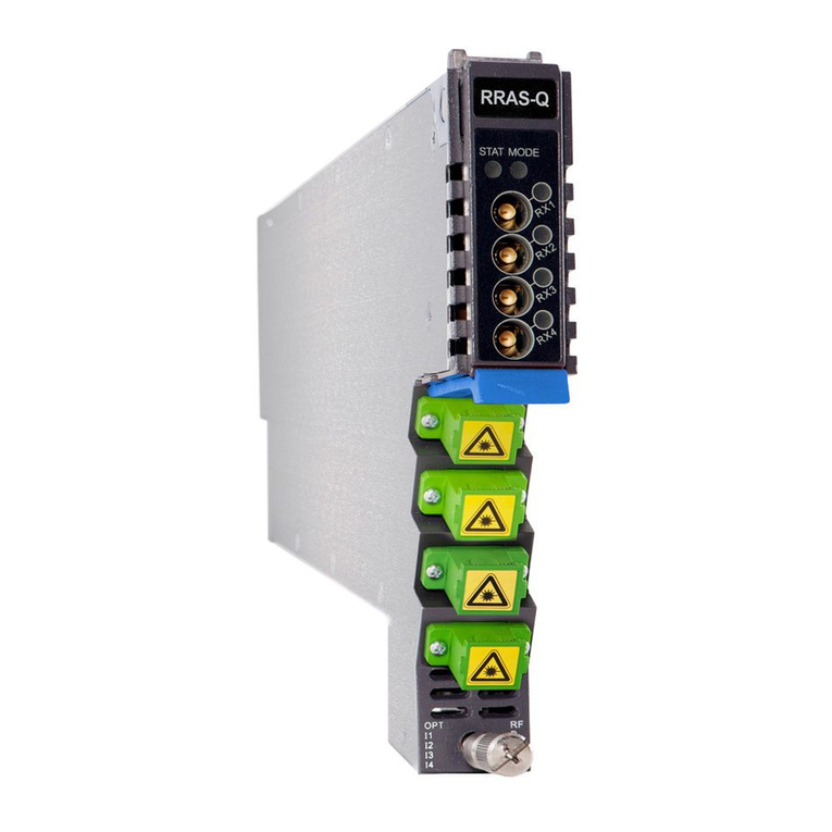
technetix AIMA-FRAS Operational manual

AIMA-FRAS
OPTICAL ANALOG
FORWARD RECEIVER
Online
Email: customer.service.[email protected]
Website: technetix.com
2018-08/EN V1
Technetix Group Limited
Product user manual

2018-08/EN V1
Product user manual
AIMA-FRAS
Technetix Group Limited
Contents
1 About this manual .....................................................................................................................................................1
1.1 Related documentation ..............................................................................................................................................................................1
1.2 Document conventions.............................................................................................................................................................................1
1.3 Technical support........................................................................................................................................................................................1
2 Precautions.................................................................................................................................................................2
3 Overview.....................................................................................................................................................................3
3.1 FRAS overview.............................................................................................................................................................................................3
3.1.1 Product description........................................................................................................................................................................3
3.1.2 Key features ....................................................................................................................................................................................3
3.1.3 Specifications..................................................................................................................................................................................4
3.1.4 Block diagram.................................................................................................................................................................................6
3.1.5 Order details ...................................................................................................................................................................................7
3.2 FRAR overview ...........................................................................................................................................................................................8
3.2.1 Product description ......................................................................................................................................................................8
3.2.2 Key features...................................................................................................................................................................................8
3.2.3 Specifications................................................................................................................................................................................9
3.2.4 Order details..................................................................................................................................................................................10
3.2.5 Block diagram...............................................................................................................................................................................11
4 Module characteristics .............................................................................................................................................12
4.1 Module appearance and port layout ....................................................................................................................................................12
4.1.1 Overview............................................................................................................................................................................................12
4.1.2 Front panel layout .........................................................................................................................................................................13
4.1.3 Rear panel layout...........................................................................................................................................................................14
5 Installation ..................................................................................................................................................................15
5.1 Preparatory work for installation ............................................................................................................................................................15
5.2 Unpacking....................................................................................................................................................................................................15
5.3 Module installation ....................................................................................................................................................................................16
5.4 Connecting optical cables ......................................................................................................................................................................17
5.4.1 Using the sliding fibre guide......................................................................................................................................................17

2018-08/EN V1
Product user manual
AIMA-FRAS
Technetix Group Limited
5.4.2 Using the fibre tray......................................................................................................................................................................20
5.4.3 Cleaning the fibre connector ends and front panel optical ports................................................................................22
5.4.4 Connecting the optical fibres...................................................................................................................................................23
5.5 Redundancy connection (for FRAR only) ...........................................................................................................................................23
5.6 Check module LEDs.................................................................................................................................................................................24
5.7 Test the optical input signal ....................................................................................................................................................................25
5.8 Test the RF output signal.........................................................................................................................................................................25
6 Module configuration and alarm setup.................................................................................................................26
6.1 Port configuration screen .........................................................................................................................................................................26
6.2 Restore factory defaults...........................................................................................................................................................................31
6.3 Reboot...........................................................................................................................................................................................................32
6.4 Alarms monitoring......................................................................................................................................................................................33
6.4.1 Alarm Status Page.........................................................................................................................................................................33
6.4.2 Module Operating Voltage and Temperature Alarm........................................................................................................34
6.4.3 Module Port Alarms.....................................................................................................................................................................35
6.4.4 Alarm Monitoring Configuration..............................................................................................................................................36
6.4.5 Input/Output Status Monitoring ...............................................................................................................................................37
6.5 Logs management ....................................................................................................................................................................................38
6.6 Device upgrade .........................................................................................................................................................................................39
6.7 FBC function description (only for FRAS-S-M) ..................................................................................................................................40
6.7.1 Spectrum...........................................................................................................................................................................................40
6.7.2 QAM analyser ................................................................................................................................................................................42
6.7.3 Constellation...................................................................................................................................................................................43
6.8 Redundancy configuration and alarms (only for FRAR).................................................................................................................46
7 Troubleshooting.........................................................................................................................................................48
7.1 Indicator for determining faults................................................................................................................................................................48

12018-08/EN V1 Technetix Group Limited
Product user manual
AIMA-FRAS
1 About this manual
1.1 Related documentation
The following documents may be used in conjunction with this manual:
■AIMA3000 - Product user manual
■AIMA ASMM - Product user manual
■AIMA3000 NMS web management system product user manual
■NMS3-EPSM - Basic inventory management
■NMS3-EPSM - Basic alarm management
■NMS3-EPSM - Basic system management
■NMS3-EPSM - Basic template management
1.2 Document conventions
Before you use the manual, please familiarise yourself with the format used in this manual.
‘*’Asterisk: Points marked with an asterisk means there is a corresponding note on the page.
1.3 Technical Support
If you need help in the process of setting up and maintaining an FPAS, please contact Technetix's technical
support sta:
Europe:
Technetix BV
Kazemat 5
NL-3905 NR Veenendaal
P.O. Box 385
NL-3900 AJ Veenendaal
The Netherlands
Phone: +31 318 58 59 59
Email: customer.service.[email protected]

22018-08/EN V1 Technetix Group Limited
Product user manual
AIMA-FRAS
2 Precautions
WARNING!
This equipment is intended for indoor applications. To prevent fire or electrical shock, or
damage to the equipment, do not expose units to water or moisture.
■You should carefully read and thoroughly understand the contents of the manual before installing
and using this equipment.
■A typical connector is the SC/APC.
Note: 8° angle polished optical connectors must be used.
■At any time, there may be dangerous voltage inside the device.
■DO NOT power up before the cover and the panels of the equipment are installed and the
enclosure is closed.
Cleaning
Only use a damp cloth to clean the front panel. Use a soft dry cloth to clean the top of the unit.
DO NOT use any spray cleaners or chemicals of any kind.
Outage or overload requiring service and repairs
Unplug the unit and refer the servicing to qualified service personnel only.
Servicing and repairs
DO NOT attempt to service this unit yourself. Refer all servicing needs to qualified service personnel only.

32018-08/EN V1 Technetix Group Limited
Product user manual
AIMA-FRAS
3 Overview
3.1 FRAS overview
3.1.1 Product description
The Analog Forward Path Receiver - Standard (FRAS) is designed to plug into the latest generation Advanced Intelligent
Multi-services Access platform - the AIMA3000.
The FRAS is available in single and dual port configurations. It incorporates a low noise front-end circuit that receives
optical wavelengths from 1260 nm to 1620 nm and converts them into RF signals for Master Antenna Television (MATV),
CATV, and broadband applications. The supported RF bandwidth is from 45 to 1218 MHz.
The module oers a superior frequency response with a low distortion profile and low noise characteristics.
The FRAS optical receiver module features automatic gain control (AGC), which is based on broadband detection or
through optional pilot signal detection.
The RF output AGC threshold level and the slope can be managed remotely.
3.1.2 Product Key Features
■Plug-and-play AIMA3000 platform module
■Superior performance with a low noise profile and minimal distortion characteristics
■High RF output for flexible deployment
■Supports Automatic Gain Control (AGC) for a stable RF output
■Electronic slope control
■Electronic gain setting and AGC adjustable thresholds
■Broadband GaAs amplifier technology
■Support for CENELEC and NTSC standards up to 110 channels (analog and digital)
■Comprehensive status monitoring and alarm with the NMS network management software
■HMS compliant
■Remote firmware upgrade and auto upload/download of configuration files through ASMM web interface or using
the NMSE
■Bulk firmware updates through the NMSE
■FCC, CE and RCM(1) compliant
(1) See Declaration of Conformity for current status.

42018-08/EN V1 Technetix Group Limited
Product user manual
AIMA-FRAS
3.1.3 Specifications
Optical performance
Optical bandwidth 1260 - 1620 nm
Optical input -5 - +3 dBm
Optical return loss > 60 dB
Optical connector SC / APC
(1), FC / APC, LC / APC, E2000 / APC
RF performance
RF bandwidth 45 - 1218 MHz
RF output level(2) 40 dBmV
RF flatness ± 0.75 dB
Gain adjustment 0 - 20 dB
Slope adjustment 0 - 7 dB
ACG range (input variation) 10 dB
AGC accuracy ±0.5 dB over AGC range
RF impedance 75 Ω
RF return loss > 16 dB
RF test point relative to RF output port -20 ± 1 dB
RF OUT connector GSK-type female
RF test point Mini-SMB
Alarms and status Front-panel LEDS, SNMP traps
Notes:
(1) Standard option. Contact a Technetix Sales Representative for availability of other options.
(2) Measured in a typical system with 0 dBm optical input, 3% - 4% OMI, and dBuV=60+dBmV.
Link Performance(1)
CNR > 53 dB
CSO > 65 dB
CTB > 70 dB

52018-08/EN V1 Technetix Group Limited
Product user manual
AIMA-FRAS
General
Power supply Powered via AIMA3000 backplane
Power consumption < 12 W (without FBC module)
< 17 W (with FBC module)
Operating temperature -5 - 55°C
Operating humidity 90% (non-condensing)
Storage temperature -25 - +70°C
Storage humidity 90% (non-condensing)
Dimensions (W*D*H) 24.6 * 410 * 152.5 mm
Weight 0.88 kg
Network management NMSE or through ASMM’s web interface
With the FBC Module
Frequency capture range 45 - 1000 MHz
Demodulation mode QAM64, QAM256
Metrics and functions available Level, SNR, MER, BER and live spectrum
Notes:
(3) Loaded with 77 NTSC channels, measured with PBN referenced optical transmitter, 0 dBm, 3% - 4% OMI.

62018-08/EN V1 Technetix Group Limited
Product user manual
AIMA-FRAS
3.1.4 Block diagram
Figure 3-1 block diagram FRAS
Table 3-1 FRAS block diagram glossary
Parameters Glossary RF
OPTICAL INPUT Optical input port
ATTENUATOR Pre-attenuator
MID AMPLIFIER Mid-stage amplifier
SLOPE Slope control
OUTPUT STAGE Post-amplifier
RF OUTPUT RF output port
RF TEST -20 dB -20 dB RF output test port
RF DETECTOR RF sensor
FBC Full band capture
BIAS Bias voltage measurement
CPU Micro-processor
TO BACKPLANE AND COMMS Module power and
communication interface
MODULE POWER SUPPLIES Supply bus

72018-08/EN V1 Technetix Group Limited
Product user manual
AIMA-FRAS
3.1.5 Order details
A-FRAS-[W]-[X]-[Y]-[Z] Analog Forward Receiver – Standard
Options:
W Optical input ports
S Single(1)
XFBC function(1)
Y Optical connector type
S SC/APC(2)
F FC/APC
L LC/APC
E E2000/APC
ZBandwidth
1G 45 - 1000 MHz (standard)
12 45 - 1218 MHz
Notes:
(1) Option for FBC Management configurations only. Please omit X when selecting a model without FBC function.
(2) Standard option. Contact a Technetix Sales Representative for availability of other options.

82018-08/EN V1 Technetix Group Limited
Product user manual
AIMA-FRAS
3.2 FRAR overview
3.2.1 Product description
The Analog Forward Receiver - Redundant (FRAR) is designed to plug into the latest generation of Advanced Intelligent
Multi-services Access platform - the AIMA3000.
The FRAR is available in single port configurations. It incorporates a low noise front-end circuit that receives optical
wavelengths from 1260 nm to 1620 nm and converts them into RF signals for Master Antenna Television (MATV), CATV, and
broadband applications. The supported RF bandwidth is from 45 to 1218 MHz.
The module oers a superior frequency response with a low distortion profile and low noise characteristics.
The FRAR optical receiver module features automatic gain control (AGC), which is based on broadband detection.
The RF output AGC threshold level and the slope can be managed remotely.
3.2.2 Product Key Features
■DOCSIS 3.1 Compatible with operating bandwidth up to 1218 MHz
■Plug-and-play with the AIMA3000 platform
■Superior performance with a low noise profile and minimal distortion characteristics
■High RF output for flexible deployment
■Supports Automatic Gain Control (AGC) for a stable RF output
■Electronic slope control
■Electronic gain setting and AGC adjustable thresholds
■Broadband GaAs amplifier technology
■Support for CENELEC and NTSC standards up to 110 channels (analog and digital)
■Comprehensive status monitoring and alarm with NMS network management software
■SCTE-HMS MIB compliant
■Remote firmware upgrade and auto upload/download of configuration files through ASMM web interface or using
the NMSE
■Bulk firmware updates through the NMSE
■Fully FCC, CE, and RCM compliant
(1) See Declaration of Conformity for current status.

92018-08/EN V1 Technetix Group Limited
Product user manual
AIMA-FRAS
3.2.3 Specifications
Optical performance
Optical bandwidth 1260 - 1620 nm
Optical input -10 - +3 dBm
Optical return loss > 50 dB
Optical connector SC/APC
(1), FC/APC, LC/APC, E2000/APC
RF performance
RF bandwidth 45 - 1218 MHz
RF output level(2) 40 dBmV
RF flatness ± 0.75 dB
Gain adjustment 0 - 20 dB
Slope adjustment 0 - 7 dB
ACG range (input variation) 10 dB
AGC accuracy ± 0.5 dB over AGC range
RF impedance 75 Ω
RF return loss > 16 dB
RF test point relative to RF output port -20 ± 1 dB
RF OUT connector GSK-type female
RF test point Mini-SMB
Alarms and status Front-panel LEDS, SNMP traps
Redundant switching time Typical: < 30 ms
Link Performance(1)
NTSC (4) CENELEC (42 ch) (5)
CNR > 52 dB > 52 dB
CSO > 68 dB > 70 dB
CTB > 70 dB > 70 dB
General
Power supply Powered via AIMA3000 backplane
Power consumption < 12 W
Operating temperature -5 - +55 °C
Operating humidity 90% (Non-condensing)
Storage temperature -25 - +70 °C
Storage humidity 90% (Non-condensing)
Dimensions (W*D*H) 24.6 * 410 * 152.5 mm
Weight 0.88 kg
Network management NMSE or through ASMM’s Web Interface
Notes:
(1) Standard option. Contact a Technetix Sales Representative for availability of other options.
(2) Measured in a typical system with 0 dBm optical input, 3% - 4% OMI.
(3) dBuV=60+dBmV.
(4) Loaded with 77 NTSC channels, measured with an optical transmitter @ 0 dBm, 3% - 4% OMI.
(5) Loaded with 42 CENELEC channels, measured with an optical transmitter @ 0 dBm, 3% - 4% OMI.

102018-08/EN V1 Technetix Group Limited
Product user manual
AIMA-FRAS
3.2.4 Order details
A-FRAR-[W]-[Y]-[Z] Analog Forward Receiver – Redundant
Options:
X Optical input ports
S Single(1)
Y Optical connector type
S SC/APC*
F FC/APC
L LC/APC
E E2000/APC
ZBandwidth
1G 45 - 1000 MHz (standard)
12 45 - 1218 MHz
Notes:
*Option for FBC Management configurations only. Please omit X when selecting a model without FBC function.

112018-08/EN V1 Technetix Group Limited
Product user manual
AIMA-FRAS
3.2.5 Block diagram
Figure 3-2 FRAR block diagram
Table 3-2 FRAS block diagram glossary
Parameters Glossary
OPTICAL INPUT Optical input port
ATTENUATOR Pre-attenuator
MID AMPLIFIER Mid-stage amplifier
SLOPE Slope control
OUTPUT STAGE Post-amplifier
RF OUTPUT RF output port
RF TEST -20 dB -20 dB RF output test port
RF DETECTOR RF sensor
BIAS Bias voltage measurement
CPU Micro-processor
TO BACKPLANE AND COMMS Module power and
communication interface

122018-08/EN V1 Technetix Group Limited
Product user manual
AIMA-FRAS
Figure 4-1 module appearance
4 Module characteristics
4.1 Module appearance and port layout
4.1.1 Overview

132018-08/EN V1 Technetix Group Limited
Product user manual
AIMA-FRAS
4.1.2 Front panel layout
Figure 4-2 FRAS front panel layout
Table 4-1 FRAS front panel functions
Item
No. Item Description
1MODE
LED
Module gain control mode indicator
MGC: Green light Blinking
AGC: Green
2 STATUS
LED
Module working alarm indicator
Normal: Green
Minor alarm: Orange
Major alarm: Red
3OPT IN
LED
Optical input signal status indicator
ON: Green
Input signal slightly high/low: Orange
Input signal too high/low: Red
4RF OUT
LED
RF output signal status indicator
ON: Green
Output RF level slightly high/Low: Orange
Output RF level too high/low: Red
5RF OUT
TP RF output test port
Item
No. Item Description
6
Orange
tab
retaining
clip
Used to plug and anchor the module.
The orange tab retaining clip will pop-up
after pressing the release and plug module
7 OPT IN Optical forward signal input port
8Mounting
screw Module fastening screw

142018-08/EN V1 Technetix Group Limited
Product user manual
AIMA-FRAS
4.1.3 Rear panel layout
Figure 4-3 FRAS rear panel layout
Table 4-2 FRAS rear panel functions
Item
Number Item Description
1 RF output port Forward RF signal output port
2 Air vent Air vent allowing air to flow out of the module
3 Multi-pin connector Power supply and communication port
4 Placement pin Used to position the module in the chassis
5 Redundancy connector RF1 input test point

152018-08/EN V1 Technetix Group Limited
Product user manual
AIMA-FRAS
5 Installation
5.1 Preparatory work for installation
Before installing this device, you must ensure that the unit is intact and ready for installation.
Unpack and check the unit: Open the box to check for any damage that may have occurred during shipment.
If damage is found, please contact a Technetix customer support representative.
Necessary equipment and tools for installation:
Table 5-1 Necessary equipment and tools for installation
5.2 Unpacking
Unpack the module. Keep the packaging materials for future transport needs.
Check the package manifest, record the product module type, serial number, purchase date, and any other relevant
information to facilitate later management and maintenance.
Table 5-2 Packing manifest
Tools/Modules Description
Phillips screwdriver PH1/PH2 For use with the AIMA3000 chassis
FRAS / FRAR module The module to install into the AIMA3000 chassis
No. Description Qty
1 FRAS/FRAR module 1
2 Product user manual (CD) 1
3 Individual test sheet (Certificate of Performance) 1

162018-08/EN V1 Technetix Group Limited
Product user manual
AIMA-FRAS
5.3 Module installation
1. Gently press down the retainer clip and release the leaver
Hinged tab AIMA module
Retaining clip
Module fastening screw
2. Hold the AIMA module casing upright, align it with the AIMA3000 slide rails for the correct slot,
and insert the module until it reaches the multi-pin connector.
DO NOT use excessive force when inserting the module, but ensure the RF connectors at the rear of the module are
securely connected to the chassis's RF connectors.
AIMA-FPAS Product User Manual
Pacific Broadband Networks 15 January 2015 Page 16 of 36
5.3 Module Installation
1. Gently depress the orange retaining clip and release the hinged tab
2. Hold the AIMA module casing upright, align it with the AIMA3000 slide rails for the correct slot,
and insert the module until it reaches the multi-pin connector.
DO NOT use excessive force when inserting the module, but ensure the RF connectors at the
rear of the module are securely connected with the chassis's RF connectors.
CAUTION!
The module MUST be installed correctly to ensure a proper
connection of the module’s multi-pin connector and the backplane.
Tip:
When inserting the module into the guide rails, vertically tilt the module slightly to check
that the guides are properly seated on the rails. The module is guided to the correct
position using the large metal fastening screw on the lower part of the front panel.
Hinged tab
Orange retaining clip
AIMA module
Module fastening screw
CAUTION!
The module MUST be installed correctly to ensure the module's multi-pin connector and
backplane are properly connected.
Tip:
When inserting the module into the guide rails, vertically tilt the module slightly to check that the
guides are properly seated on the rails. The module is guided to the correct position using the large
metal fastening screw on the lower part of the front panel.
Table 5-1 Depress the clip and release the hinged tab

172018-08/EN V1 Technetix Group Limited
Product user manual
AIMA-FRAS
3. After the module is inserted, gently push the hinged tab until it snaps into the retaining clip. While pushing
down on the hinged tab, the AIMA module will pair with the power bus and will lock into the chassis.
4. When the module is fully seated within the chassis, on the AIMA module, fasten the spring-loaded mounting
screw. Only use fingers to fasten the mounting screw. DO NOT use a screwdriver.
5.4 Connecting optical cables
For the convenience of the user, the AIMA3000 Chassis has a Sliding Fiber Guide to help the operator to arrange the
cables. For the specific steps to connect the fibre, please refer to the instructions in section 5.4.1.
5.4.1 Using the sliding fibre guide
The sliding fibre guide is located in the lower-left corner of the chassis if looking at the front of the chassis, and is
designed to help installation of the optical fibre cabling. To access the sliding fibre guide you will need to remove the rear
panel located on the back of the chassis firstly.
CAUTION!
If force is required to insert a module, then it may not be correctly seated on the slide rails,
or the mounting screw may be misaligned.
1. Unscrew the two thumbscrews on the rear panel.
Figure 5-3 unscrew the thumbscrews on the rear panel
Table of contents
Other technetix Receiver manuals
