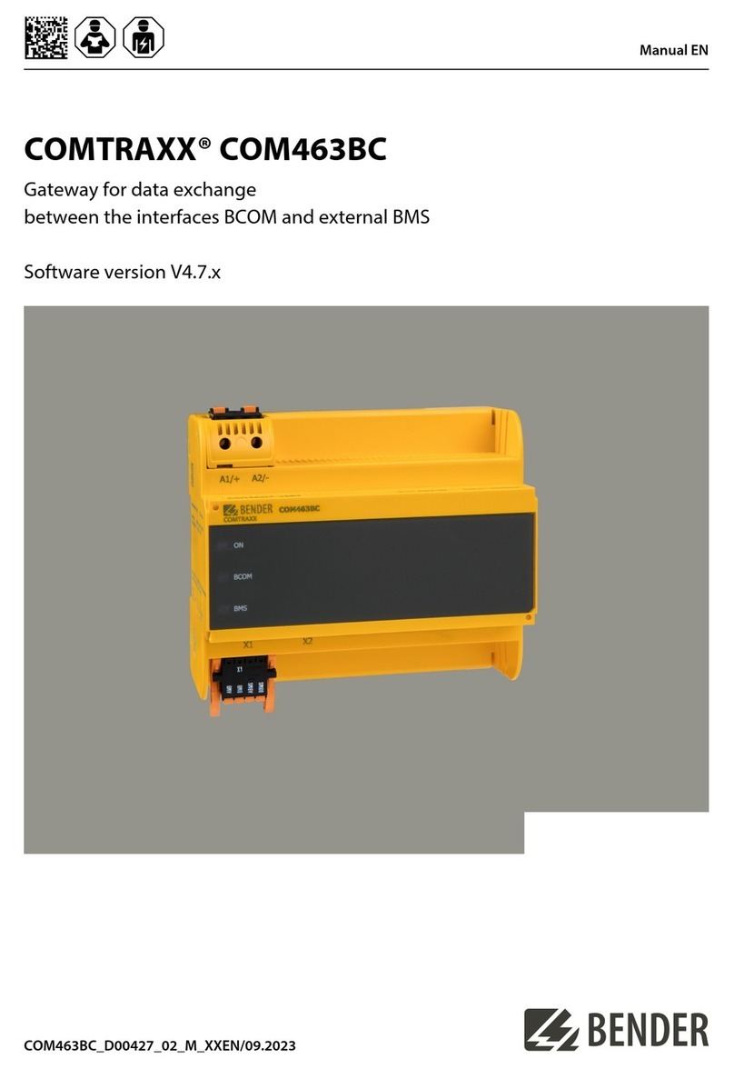
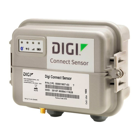
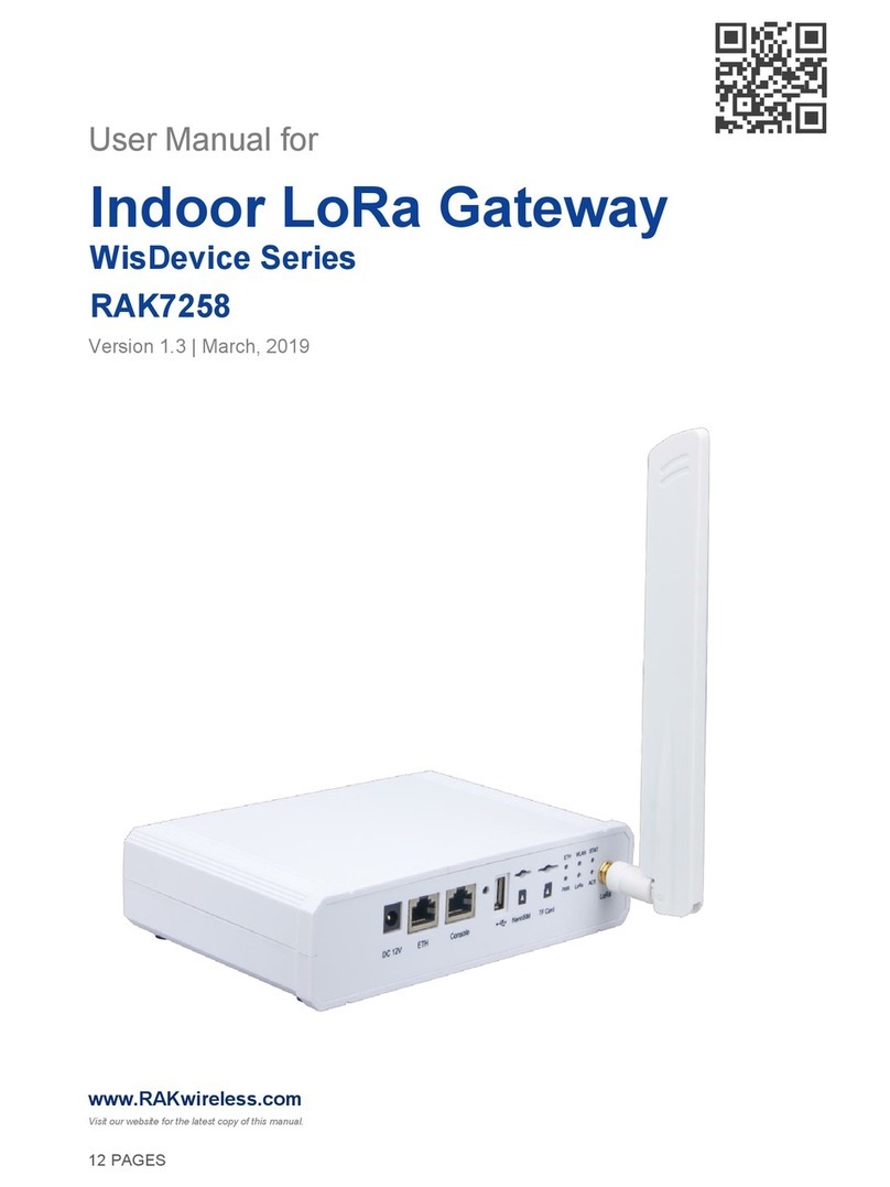
Technica Engineering MEDIAGATEWAY User manual

MEDIAGATEWAY
Manual-Version: 5.0
HW-Version: v2.1a to v2.6
USER MANUAL
March 2020
FW-Version: v4.4.0

MEDIAGATEWAY User Manual
2
CONTENT
1GENERAL INFORMATION........................................................................................... 5
1.1 Functionality and Features of the MediaGateway ............................................. 5
1.2 Warranty and Safety Information ........................................................................ 7
1.3 Declaration of Conformity.................................................................................... 8
1.4 Scope of Delivery .................................................................................................. 9
2HARDWARE INTERFACES ........................................................................................ 10
2.1 Connectors..........................................................................................................10
2.1.1 Power Connector - Black MQS Connector................................................. 11
2.1.2 Switch Connectors –Blue MQS Connectors.............................................12
2.1.3 RJ-45 Ethernet connectors .........................................................................13
2.1.4 SFP Slot ........................................................................................................ 13
2.1.5 Micro HDMI connector ................................................................................ 13
2.2 Other Interfaces .................................................................................................. 13
2.2.1 Status LEDs..................................................................................................13
2.2.2 Push Button (Reset to default) ................................................................... 14
3CONFIGURATION OF DEVICE................................................................................... 15
3.1 Access to Webserver.......................................................................................... 15
3.2 Save changes......................................................................................................15
3.3 System Information tab...................................................................................... 16
3.4 Control Panel tab ................................................................................................ 17
3.4.1 Control panel................................................................................................ 17
3.4.2 MediaGateway Feature Activation ............................................................. 18
3.5 Switch Status tab................................................................................................ 20
3.5.1 Global Configuration ................................................................................... 20
3.5.2 ARL Table Status ......................................................................................... 21
3.5.2.1 Dynamic ARL Table .............................................................................. 22
3.5.2.2 Static ARL Table ................................................................................... 23
3.5.3 Ports overview ............................................................................................. 27
3.6 Port Information (dependent on Global configuration mode) ........................27
3.6.1 Ports Information while No VLAN tagging is active ................................. 27
3.6.1.1 Ethernet Port RJ-45 .............................................................................. 28
3.6.1.2 SFP module port ...................................................................................30

MEDIAGATEWAY User Manual
3
3.6.1.3 S1-P4 (CPU) and internal ports (P4 and P8) ...................................... 32
3.6.1.4 100BASE-T1 Ports ................................................................................ 33
3.6.2 Port Information while Single VLAN tagging is active.............................. 35
3.6.2.1 Ethernet Port RJ-45 .............................................................................. 36
3.6.2.2 SFP module port ...................................................................................38
3.6.2.3 S1-P4 (CPU) and internal ports (P4 and P8) ...................................... 40
3.6.2.4 100BASE-T1 Ports ................................................................................ 42
3.6.3 Port Information while Double VLAN tagging is active ............................ 44
3.6.3.1 Ethernet Port RJ-45 .............................................................................. 45
3.6.3.2 SFP module port ...................................................................................47
3.6.3.3 S1-P4 (CPU) and internal ports (P4 and P8) ...................................... 50
3.6.3.4 100BASE-T1 Ports ................................................................................ 52
3.6.4 Important VLAN tagging rules.................................................................... 54
3.7 CAN Gateway ...................................................................................................... 55
3.7.1 Communication mode: UDP ....................................................................... 57
3.7.2 Communication mode: Raw .......................................................................59
3.7.3 Communication mode: Speed RAW...........................................................61
3.7.4 Communication mode: Extreme RAW .......................................................63
3.7.5 Difference between all RAW modes........................................................... 66
3.7.6 Structure of a CANEthernet packet........................................................ 66
3.7.6.1 Structure of UDP-Packet ...................................................................... 66
3.7.6.2 Structure of RAW-Packet ..................................................................... 66
3.7.6.3 Structure of Payload from the UDP or RAW ethernet frame.............66
4Configuration Examples ........................................................................................... 68
4.1 Logging communication between two DUTs ................................................... 68
4.2 Get access by third communication partner .................................................... 71
5PTP AND 802.1AS in the MediaGateway ................................................................ 73
5.1 Protocol ............................................................................................................... 73
5.2 Transport of time-synchronization information............................................... 73
5.3 Propagation delay measurement ...................................................................... 75
5.4 802.1AS in the MediaGateway...........................................................................76
5.5 Limitations in MediaGateway using 802.1AS................................................... 76
6Diagnostic Frames .................................................................................................... 77
6.1 Board Configuration Frame (0x8001) ............................................................... 77

MEDIAGATEWAY User Manual
4
6.2 Port Information Frame (0x8002) ..................................................................... 79
7MediaGateway Remote Control ...............................................................................81
7.1 Reset Device........................................................................................................ 82
7.2 Import Configuration .......................................................................................... 82
7.3 Export Configuration .......................................................................................... 83
7.4 Dynamic Configuration....................................................................................... 83
7.5 Check Status ....................................................................................................... 83
7.6 Set WakeUp Line Status.....................................................................................84
7.7 Get WakeUp Line Status.....................................................................................84
7.8 Set Port Enabled/Disabled (only 100BASE-T1-Ports)...................................... 85
7.9 Set Port to Master/Slave (only 100BASE-T1-Ports)......................................... 86
7.10 Reset to default ............................................................................................... 87
7.11 Get System Information.................................................................................. 87
8APPLICATION AND FIRMWARE UPDATE ............................................................... 89
8.1 Preconditions and important information ........................................................ 89
8.2 Update .................................................................................................................89
9TROUBLESHOOTING AND FAQ................................................................................ 90
9.1 All 100BASE-T1 LEDs are lit permanently.........................................................90
9.2 Four 100BASE-T1 LEDs of one Switch are lit permanently............................. 90
9.3 No access to webserver anymore.....................................................................90
9.4 Host LED is blinking fast.................................................................................... 90
9.5 Problems with website interface....................................................................... 91
9.6 Delay Time for Ethernet packets through the MediaGateway ........................91
9.7 AVB Support........................................................................................................91
9.8 Maximum Frame Size......................................................................................... 91
10 LIST OF FIGURES....................................................................................................... 92
11 CHANGELOG ............................................................................................................. 94
12 CONTACT................................................................................................................... 95

MEDIAGATEWAY User Manual
5
1GENERAL INFORMATION
1.1 Functionality and Features of the MediaGateway
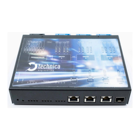
Figure 1-1: MediaGateway
The Technica Engineering MediaGateway allows users to connect and loop through
up to 12 100BASE-T1-based devices on the physical layer and to establish virtual point-
to-point connections, thus enabling filter and control of data streams (routing,
mirroring, forwarding).
It can work as Converter between 100BASE-T1 and Standard Ethernet.
Extra functions as CAN-Gateway and FlexRay Logging are available.
Features:
12 Ports 100BASE-T1 Ethernet
Ports Gbit Ethernet (10/100/1000) BASET Full duplex) for Logging data output
and configuration
1 Port Gigabit Ethernet SFP module socket
Automotive Tyco MQS Connector for 100BASE-T1 and power supply
Easy configuration via webserver and via data telegram
Import and export of configuration
Wake up functionality
CAN/LIN/FR interfaces (requires customer specific software)
Power output for attached devices (VBAT max. 1,2 Ampere in total [Fused])

MEDIAGATEWAY User Manual
6
Possibility to reset to default settings by pushbutton
Robust steel case
General Information:
Power requirement:
7 to 16 Volt DC (nominal 12 Volt DC)
Power consumption:
7-12 Watt
Size:
195 x 143 x 33 mm
Weight:
0,77kg
International Protection:
IP 2 0
Operating temperature:
-40°Celsius to +80°Celsius
StartUp Time
The StartUp time is valid for HW-Variants 2.1a and higher, and Software 3.7 and higher.
If there is information needed about older variants of the MediaGateway, please
PowerUp and Processor Boot Time:
65
ms
Configuration Time depending on complexity
47-55
ms
100BASE-T1 LinkUp Time
20-130
ms
Note: The RJ-45 GB-Ports need about 3-4 seconds linkup time due to Autonegotiation.
LINKS:
The User can download the latest firmware and documentation for the MediaGateway
here:
https://technica-engineering.de/produkt/media-gateway/

MEDIAGATEWAY User Manual
7
1.2 Warranty and Safety Information
Before operating the device, read this manual thoroughly and retain
it for your reference.
The latest documentation for the MediaGateway can be downloaded
here:
https://technica-engineering.de/produkt/media-gateway/
Use the device only as described in this manual.
Use only in dry conditions.
Do not apply power to a damaged device.
Do not open the device. Otherwise warranty will be lost.
This device is designed for engineering purpose only.
Special care has to be taken for operation.
Do not use this device in a series production car.
As this device is likely to be used under rough conditions, warranty is
limited to 1 year.
Manufacturer liability for damage caused by using the device is
excluded.
Caution: The device can get hot.
Do not cover the device due to fire danger.
Do not place the device near to highly flammable materials due to fire
danger.
If you wish to discard a 100BASE-T1 MediaConverter from Technica
Engineering GmbH, please contact your dealer or supplier for further
information.
This symbol is only valid in the European Union. If you wish to discard
this product, please contact your local authorities or dealer and ask
for the correct method of disposal. Technica Engineering GmbH is
registered as manufacturer of the brand "Technica Engineering" and
the device type "Small devices of Information- and
Telecommunications- technology for exclusive use in non-private
Households”. WEEE reg. No. DE 20776859

MEDIAGATEWAY User Manual
8
1.3 Declaration of Conformity
Figure 1-2: Declaration of conformity

MEDIAGATEWAY User Manual
9
1.4 Scope of Delivery
The delivery includes:
1x MediaGateway
1x Cable-set
o1x 1m Ethernet Cable
o1x Black MQS Connector
o3x Blue MQS Connectors
o100BASE-T1 cabling
oMQS Crimps
oPower cabling
o4mm Banana-plugs
Additional cable-sets can be ordered. Please write us at order@technica-
engineering.de.

MEDIAGATEWAY User Manual
10
2HARDWARE INTERFACES
2.1 Connectors
On the label on top of the device you can see an overview about all HW interfaces of
the MediaGateway:
Figure 2-1: Label of MediaGateway with pinning information

MEDIAGATEWAY User Manual
11
2.1.1 Power Connector - Black MQS Connector
The Tyco Electronics (TE) Micro Quad Lock System (MQS) is used.
Name
Picture
Part Number
Tyco, MQS Abdeckkappe 2x9 Pol, black
Alternative
1-967416-1
1-1355350-1
Tyco, MQS Buchsengehäuse 2x9 Pol
Alternative
965778-1
962108-2
Tyco crimp contact
928999-1
Table 2—1: Parts of black MQS connector
Note: You can use the official Tyco tool for these crimp contacts. A cheaper variant is
the crimp tool for “PSK” contacts.
Pin
Function
Pin
Function
1
Battery +12 Volt Input
10
Wake up line 3 (Output only)
2
Power Ground
11
CAN E plus
3
CAN C plus
12
CAN E minus
4
CAN C minus
13
CAN D plus
5
CAN A plus
14
CAN D minus
6
CAN A minus
15
CAN B plus
7
Wake up line 2
16
CAN B minus
8
Wake up line 1
17
FlexRay plus
9
LIN Bus
18
FlexRay minus
Table 2-2: Pinning of black MQS connector
Note: CAN interfaces can only be used with CAN Gateway option and FlexRay Logging
only with FlexRay option. For further Information please contact
The power supply for the device is supplied by Pin 1 (12Volt) and Pin 2 (Ground).
Requirements for the MediaGateway itself: 12 Volts DC up to 1 Ampere (typical
600mA)

MEDIAGATEWAY User Manual
12
Please note, that the power supply for the 12 Volts camera power output is also
supplied form Pins 1 and 2.
Warning: If you apply a voltage higher than 16 Volts, the device will be damaged!
A wake-up line can be connected on Pins 7 or 8. The wake-up line should have the
same voltage level as the power supply (12 Volts). A high level on one of these pins
wakes up the ECU from sleep mode and keeps it active. If the voltage on this pin drops
below approx. 6 Volts for more than about 3 seconds, the ECU will enter sleep mode
until voltage increases and it wakes again.
The LIN interface on Pin 9 can be used to communicate with the microcontroller by
LIN bus. In the default software there is no data transmission specified. This interface
may only be used in customer specific software.
The FlexRay interface on Pins 17 and 18 can be used to communicate with the
microcontroller by the FlexRay bus. In the default software there is no data
transmission specified. This interface may only be used in customer specific software.
2.1.2 Switch Connectors –Blue MQS Connectors
The Tyco Electronics (TE) Micro Quad Lock System (MQS) is used.
Pin
Function
Pin
Function
1
Camera +12 Volt nominal output
10
100BASE-T1 port 3, plus
2
Camera Ground output
11
100BASE-T1 port 3, minus
3
100BASE-T1 port 2, minus
12
Camera Ground output
4
100BASE-T1 port 2, plus
13
Camera +12 Volt nominal output
5
n.c.
14
n.c.
6
100BASE-T1 port 1, plus
15
Camera +12 Volt nominal output
7
100BASE-T1 port 1, minus
16
Camera Ground output
8
Camera +12 Volt nominal output
17
100BASE-T1 port 0, minus
9
Camera Ground output
18
100BASE-T1 port 0, plus
Figure 2-2: Pinning of blue MQS connectors
The pins marked with (P) or (N) are used for the 100BASE-T1 ports. Four ports are
available per switch.
You have to connect the (P) pin to the (P) pin of the periphery device. You have to
connect the (N) pin to the (N) pin of the periphery device.
Note: If you swap these two pins, the link LED may be lit on the 100BASE-T1 slave side,
but no data transmission will be possible.
The pins marked with (+) or (-) are 12 Volts power output pins. The actual voltage level
of these pins depends on the supply voltage of the ECU. Be aware that the sum of all

MEDIAGATEWAY User Manual
13
12 power output pairs will deliver a maximum of 1.2 ampere. If more current is used
the output will temporarily switch off.
The power output has to be switched on by website configuration (Control panel).
2.1.3 RJ-45 Ethernet connectors
There are three RJ-45 Standard Ethernet Connectors at the front side for Gigabit
Ethernet. They are working with autonegotiation for 10/100/1000 Mbps.
2.1.4 SFP Slot
There is one SFP cage for a MiniGBIC module.
The following modules have been tested:
Edimax Mini GBIC (SFP) LC, 1 Gigabit/s, 1000 Base-SX Module
SFPEX S1GT-A Mini GBIC (SFP) 10/100/100 Mbps RJ-45 Module
BEL SFP-1GBT-05 SFP 10/100/100 Mpbs RJ-45 Module
Note: Technica Engineering´s 100/1000BASE-T1 SFP Modules are compatible with the
MediaGateway!
For further information please follow these links:
https://technica-engineering.de/en/produkt/100base-t1-sfp-module/
https://technica-engineering.de/en/produkt/1000base-t1-sfp-module/
2.1.5 Micro HDMI connector
This is an interface for programming and debugging (only for development.)
2.2 Other Interfaces
2.2.1 Status LEDs
The MediaGateway has several status LEDs at the front side of the case.
Figure 2-3: LEDs

MEDIAGATEWAY User Manual
14
The “Host” LED can toggle at three different speeds:
Slow toggle (approx. 0.5 sec) during normal operation to show that the
microcontroller is running in normal mode.
Fast toggle (approx. 0.1 sec) when the microcontroller is in bootloader mode.
The bootloader mode is used for firmware update only (see below in this
manual). You cannot access the website when the device is in bootloader
mode.
When the device is in bootloader-update mode the LED toggles with moderate
frequency (ap- prox. 0.25 sec).
Note: If the HOST LED is stuck, the microcontroller is overstrained. Please make sure
that only necessary communication hits the microcontroller port (S1-P4) and try a
power reset.
The 12 port status LEDs of all 100BASE-T1 Ports monitors the link status of the
corresponding port. The LEDs are lit when there is a BroadR-Reach link detected. They
begin to blink when there is data traffic on this link.
Note: There is a known issue: Whenever P/N of the bus swap, data transmission won’t
be possible, not even if the LED is lit in the 100BASE-T1 slave side.
The In-built LEDs in RJ-45 connector shows the status of the gigabit ports. The left
(orange LED) is lit by a link-up. The right (yellow) will blink on data traffic.
2.2.2 Push Button (Reset to default)
The push button on the very left side at the front side of the case (hole) will reset all
settings to factory default.
Press this button down for 5 to 6 seconds with a pointy stick or pen while the HOST
LED is blinking normally.
After that:
IP Address are set to default (192.168.0.49)
Complete configurations are lost and set to default
Note: If the device is blocked and all LEDs are lit, device must be sent to Technica
Engineering. In order to avoid controversues here please make sure that the HOST LED
is blinking its normal operation mode and the power supply is stable before the reset.

MEDIAGATEWAY User Manual
15
3CONFIGURATION OF DEVICE
3.1 Access to Webserver
You get access to the Webserver by connecting the device via a GB-port (RJ-45) to
your PC.
1. Please go to the network adapter settings of your PC and adjust the IP in the
same range of your MediaGateway. Default-IP address of the MediaGateway is
192.168.0.49, the subnet mask is 255.255.255.0.
2. Enter the IP address of the MediaGateway in your browser.
Note: Firefox is the recommended browser.
3. The following website should appear:
Figure 3-1: Home Screen MediaGateway
Note: If there is a lot of broadcast traffic on the switch, the host microcontroller
may be jammed. You cannot access the website in this case. Please use VLAN
configuration to forward only relevant messages to the microcontroller.
Sometimes a power reset works, too.
Please select one of the tabs for further configuration.
3.2 Save changes
If you changed anything in the configuration the following hint appears every time:
Figure 3-2: Save Configuration

MEDIAGATEWAY User Manual
16
You don’t have to save every time when this hint appears. You can make all wished
changes and save the configuration at the end. Please check the box “restart after
saving” and then press the “Save configuration” button.
After the restart, all changes are applied.
3.3 System Information tab
Figure 3-3: System Information tab
On the tab “System Information“, some status information about the device is
displayed. You can check the version number of the application firmware and the
bootloader or the unique MAC address of the device. The version number registers of
the switch and PHY chips are displayed for information only.
MediaGateway UUID: Since version 4.1.12 the UUID is shown. This UUID is need for
activation of extra features.
MAC address: This MAC address should be the same as on the label on the bottom of
the device.
IP address: You can change the IP address of the host microcontroller (Webserver)
here. If you want to use multiple devices in one network, you must configure a unique
IP address for each device here.
Note: If you forgot the IP address of your device you can reset it to default as described
in CHAPTER 2.2.2

MEDIAGATEWAY User Manual
17
3.4 Control Panel tab
3.4.1 Control panel
Figure 3-4: Control Panel tab
Restart target: Software reset. Configuration will NOT be lost.
Configuration: It shows the current configuration name.
Export: Save the stored configuration from MediaGateway into user’s PC.
Import: User can import or export the configuration settings of the device to a file
(*.cfg) on a computer connected to the RJ45 Port. A restart is needed to apply the new
configuration.
Default: You can reset the configuration settings to default. All values will be set to
default except the IP address. It will be not modified.
Enable camera power: The camera power output pins are disabled by default. To
activate them, this checkbox should be checked.
Prevent sleep: If you do not want to use a Wakeup line, you can enable the “Prevent
sleep” checkbox (default). This will keep the device running without entering the sleep
mode. If this option is disabled, the device will go to sleep if no activity is recognized
according to observed ports. (Please see the configuration of each port in CHAPTER
3.6)
Diagnose service: If you enable this functionality, the MediaGateway will send
periodically status information about its state. For example, transmitted and dropped
frame counters, link quality, etc. For more details please see CHAPTER 6

MEDIAGATEWAY User Manual
18
3.4.2 MediaGateway Feature Activation
MediaGateway features and Activation key:
CAN Gateway
FlexRay Gateway
BMW Extra Functions (not available)
For activation of the extra features (CAN Gateway, FlexRay Gateway) an activation key
is needed. Please contact order@technica-engineering.de if you want to order an
information about the conditions of these features.
following information:
Order number
UUID of the MediaGateway
Ordered Feature
Figure 3-5: UUID of MediaGateway
Technica Engineering will provide an activation code for the feature. The received
activation code must be entered in the Control Panel.
The next picture shows how to unlock CAN Gateway feature after receiving the
activation code:

MEDIAGATEWAY User Manual
19
1. Select the feature: e.g. CAN Gateway
2. Insert the code
3. Save configuration and restart the device.
Figure 3-6: How to unlock feature
Now there is an extra tabulator for the extra feature available:
Figure 3-7: CAN Gateway tabulator
Remove extra features: With this function all extra features will be removed from this
MediaGateway. If this is done, reactivation is possible with the Activation key again.

MEDIAGATEWAY User Manual
20
3.5 Switch Status tab
Figure 3-8: Switch Status tab
The main configuration of the MediaGateway is done in the “Switch Status“tab.
Here you can configure details about each port and get some status information
about the ports and switch states.
On the left side of the page you can see an overview of all available ports. A blue bar
at the side of a port label indicates an active link (On the Cascade SFP port there is no
linkup indication).
3.5.1 Global Configuration
In global configuration, user can change global settings affecting all three switches
inside MediaGateway.
IEEE 802.1q (VLAN) mode: Activates port based Single VLAN.
Double Tagging: If IEEE 802.1q (VLAN) mode is activated, it is possible to work with
double tagging. It is only possible to activate it if single tagging is already activated.
Other manuals for MEDIAGATEWAY
1
Table of contents
Other Technica Engineering Gateway manuals
