X-Trax VATA2020 User manual

Product User Manual
IP-Gateway
Model: VATA2020
Version:V1.0.60.16

Sa ety Notices
Please read the ollowing sa ety notices be ore installing or using this gateway.
They are crucial or the sa e and reliable operation o the device.
Please use the external power supply that is included in the package. Other
powers supplies may cause damage to the device, a ect the behavior or
induce noise.
Be ore using the external power supply in the package, please check with
home power voltage. Inaccurate power voltage may cause ire and damage.
Please do not damage the power cord. I power cord or plug is impaired, do
not use it, it may cause ire or electric shock.
The plug-socket combination must be accessible at all times because it serves
as the main disconnecting device.
Do not drop, knock or shake it. Rough handling can break internal circuit
boards.
Do not install the device in places where there is direct sunlight. Also do not
put the device on carpets or cushions. It may cause ire or breakdown.
Avoid exposure the gateway to high temperature, below 0℃ or high humidity.
Avoid wetting the unit with any liquid.
Do not attempt to open it. Non-expert handling o the device could damage it.
Consult your authorized dealer or help, or else it may cause ire, electric
shock and breakdown.
Do not use harsh chemicals, cleaning solvents, or strong detergents to clean
it. Wipe it with a so t cloth that has been slightly dampened in a mild soap and
water solution.
When lightning, do not touch power plug or device line, it may cause an
electric shock.
Do not install this device in an ill-ventilated place.
You are in a situation that could cause bodily injury. Be ore you work on any
equipment, be aware o the hazards involved with electrical circuitry and be
amiliar with standard practices or preventing accidents.

Table o Content
1. WELCOME TO THE VATA2020 SINGLE PORT GATEWAY ......................................................................... 4
1.1. Package Contents ....................................................................................................................... 4
2 UNDERSTANDING OF A SINGLE PORT GATEWAY VATA2020 ..................................................................... 5
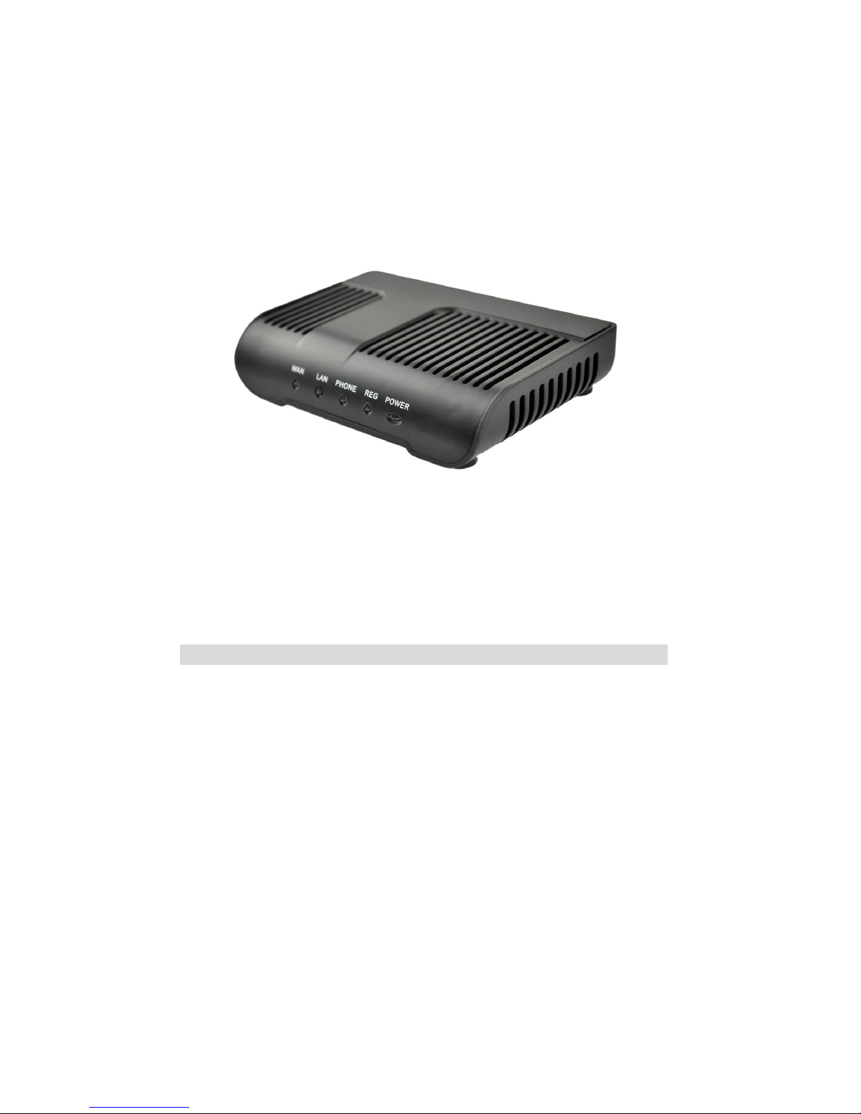
2.1. The VATA2020 single port gateway ............................................................................................ 6
2.2. Indicator signs ............................................................................................................................ 6
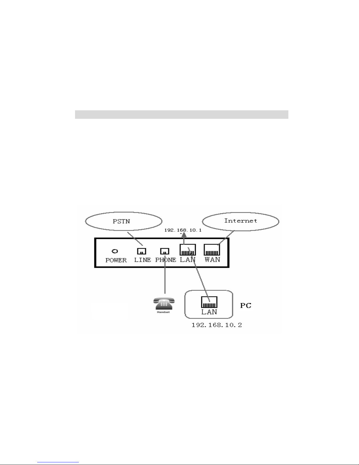
2.3. Connector description ................................................................................................................
3. GETTING STARTED .............................................................................................................................. 8
3.1. Connect the power and network ................................................................................................. 8
3.1.1. Conn ct th n twork .......................................................................................................................... 8
3.1.2. Conn ct th pow r ............................................................................................................................. 9
4. VATA2020 BASIC OPERATION OF A SINGLE PORT GATEWAY PHONE ...................................................... 10
4.1. Call transfer ............................................................................................................................. 10
4.2. Call hold ................................................................................................................................... 10
4.3. With the PSTN user calls .......................................................................................................... 11
5. WEB CONFIGURATION ........................................................................................................................ 12
5.1. Introduction of configuration ................................................................................................... 12
5.1.1. Ways to configur ............................................................................................................................ 12
5.1.2. Password Configuration ................................................................................................................... 12
5.2. Setting via web browser ........................................................................................................... 12
5.3. Configuration via WEB ........................................................................................................... 13
5.3.1. BASIC ............................................................................................................................................. 13
5.3.2. N twork .......................................................................................................................................... 16
5.3.3. VOIP ................................................................................................................................................ 23
5.3.4. Phon ............................................................................................................................................... 32
5.3.5. Maint nanc .................................................................................................................................... 36
5.3.6. S curity ............................................................................................................................................ 41
5.3.7. Logout ............................................................................................................................................. 46
6. APPENDIX ......................................................................................................................................... 47
6.1. SPECIFICATION ............................................................................................................................... 47
6.1.1. HARDWARE ................................................................................................................................. 47
6.1.2. VOICE FEATURES ......................................................................................................................... 47
6.1.3. NETWORK FEATURES ................................................................................................................... 47
6.1.4. MAINTENANCE AND MANAGEMENT .............................................................................................. 48
6.2. PARTICULARLY SUITABLE FOR VATA2020 SINGLE PORT GATEWAY ................................................... 48
6.3. COMMON PROBLEMS ...................................................................................................................... 48

1. Welcome to the VATA2020 single port gateway
1.1. Package Contents
Please check your product packaging,it includes:
1. One VATA2020 single port gateway
2. A group o cable
3. A power adapter
NOTE: if you use the non-VATA2020 single port gateway comes with a power adapter, single
port gateway VATA2020 may cause damage or other in ury. Specifications for the power
adapter may difference between the different ship areas ,If the power adapter provided
with the product can not be used locally, please consult your local dealer.
4. User manual

2 Understanding o a single port gateway VATA2020
VATA2020 Single-port gateway IP-based voice media access device is designed or
operators, enterprises, residential users, and residential VoIP solution to provide
network equipment. VATA2020 single port gateway into the analog voice
in ormation transmitted over IP networks, which use IP networks to transmit voice.
It is ull compliance with the SIP protocol standard, with the market most other SIP
compliant devices and server-side.
The gateway will play Internet network (either public network or private network)
connecting with the public telephone network bridge. It provides an FXS analog
voice inter ace, used or ordinary small business PBX or gateway (PBX). Also
provide an additional inter ace to a public telephone network PSTN (IE escape
inter ace); power or the gateway, the call line will automatically go to PSTN lines
rom the VoIP line, the normal tra ic or the user to provide the most e ective
protection.
O this site using the most advanced voice processing technologies, such as
advanced voice compression standards, echo cancellation, dynamic voice
detection, silence detection, ensuring Quality o Service (QoS), voice quality
comparable to regular PSTN phone.
In addition, VATA2020 single port gateway also integrates a small router unction.
WEB comes through the gateway con iguration page, simply con igure the
network parameters, can achieve multiple computers and network equipment,
broadband access, ideal or small o ice and home users.
Because this site has a wealth o eatures and related detailed con iguration
options, in your call to enjoy a stress ree be ore you know your VATA2020 single
port gateway.

2.1. The VATA2020 single port gateway
2.2.
Indicator signs
Name Meaning Description
POWE
R
Power LED Always light, has power, you
can start using the VATA 0 0
single port gateway.
REG Registration
status
indicator
Registered, the lights lit, the
registration fails, the light
flashes; do not use Notes
Books, lights out.
PHONE Phone work
status lights
Show VoIP service is being
used, or PSTN services,
service, hang up: Death; pick
up after the state if it is VoIP,
Always; if you are in PSTN
state: off.
WAN WAN network
interface lights
Indicator light, WAN port
connected to the network.
Flashing: Data transfer.

LAN LAN network
interface lights
Indicator light, LAN port
connected to the network.
Flashing: Data transfer.
2.3. Connector description
Name Meaning Description
POWE
R
Power switch Output:1 VDC
,
500mA
。
LINE Lifeline PSTN access lines.
PHONE FXS Interface Ordinary telephone connection,
or switch into the line.
LAN Network
Interface
10/100M Adaptive connected PC.
WAN Network
Interface
10/100M Adaptive connected to
the RJ45 port of Internet
。
VATA2020 single port gateway with two network inter ace itsel : WAN port and LAN
port, you can use the Internet connection into the WAN port or LAN port. Be ore
inserting the power to read the manual care ully o “Sa ety."

3. Getting Started
Be ore you start using the VATA2020 single port gateway, please install the
ollowing:
3.1. Connect the power and network
3.1.1. Connect the network
During this step, make sure your environment already have broadband Internet
access capability.
1. Broadband Router
Direct network connection—by this method, you need at least one available
Ethernet port in your workspace. Use the Ethernet cable in the package to connect
WAN port on the back o your phone to the Ethernet port in your workspace. Since
this VoIP Phone has router unctionality, whether you have a broadband router or
not, you can make direct network connect. The ollowing two igures are or your
re erence.
2. as a broadband router
Use this method i you have a single Ethernet port in your workspace with your
desktop computer already connected to it. First, disconnect the Ethernet cable
rom the computer and attach it to the WAN port on the back o your phone. Next,
use the Ethernet cable in the package to connect LAN port on the back o your
phone to your desktop computer. Your IP Phone now shares a network connection
with your computer. The ollowing igure is or your re erence.

3.1.2. Connect the power
During this step, make sure your power supply connector and a single port
gateway VATA2020 outlet match, while VATA2020 is also in line voltage and current
required or a single port gateway.
1. The trans ormer connected to the DC port on the back o VATA2020 single port
gateway POWER jack
2. The AC adapter plug to an electrical outlet, VATA2020 single port gateway boot.
3. At this point all o your lights (except the POWER indicator) will lash together.
A ter booting, you will hear popping sounds, and then the indicator light is lit
according to your current con iguration corresponding light. (I your light is not
normal, you need to urther con igure your network connection mode)
4. I you login on the gateway server, then you can start calling

4. VATA2020 Basic operation o a single port gateway
phone
4.1. Call trans er
Blind Trans er
During a call, press FLASH (Flash) key, enter the number to be trans erred * add
and press
【#】 key to con irm, you can trans er the current call to third parties. (To
use this eature, you must enable the gateway o the Call Waiting and Call Trans er
unction)
Attended Trans er
During a call, press FLASH (Flash) key, enter the number waiting to be trans erred
connected, directly hang up, you can trans er success ully. (To use this eature,
you must enable the gateway o the Call Waiting and Call Trans er unction)
NOTE:1, Call Trans er must call in two cases all the way is ree or operation;
2, Gateway (trans er side) and the establishment o phone A calls phone C gateway
and then create a call, hang up the phone A, this time the gateway can also initiate
the trans er.
3, your VoIP tra ic services providers need to support (RFC3515), this eature to
work correctly.
4.2. Call hold
Call Hold and set aside
During a call you can press FLASH (FLASH) button and enter the number to dial
and press 【#】 key to ensure
Recognition, can retain the current state o the call with third-party calls. I you
press the FLASH (Flash) key, you can switch back. You also can send and receive
on one side, then the party can not be retained to hear your conversation, the
speaker you can not. During a call i you press 【*】 operation, will enter the three-
way calling mode. (To use this eature, you must enable the gateway o the Call
Waiting eature, you must achieve three-way calling mode to start the gateway
Three Way Call unction)
Call on hold and accept call waiting
In normal conversation, a third party dial-in, the handset will beep ~ beep ~ tips
coming, you can use FLASH (Flash) button to accept call waiting. I you press this

button again, you can switch back. You also can send and receive on one side,
then the party can not be retained to hear your conversation, the speaker you can
not. (To use this eature, you must enable the gateway o the Call Waiting eature)
4.3. With the PSTN user calls
* T mapping shows that when the user connected to the PSTN line to the LINE
port, then press * to switch to PSTN line, the user can call through the PSTN; i re-
hook-hook dialing, the de ault line, or VoIP, need to press * to switch.
O course you can also set the others, does not necessarily use the * T (Finally,
the T end)
(See speci ic operations 5.3.3 Dial-peer)
Li eline o the main unctions is: to prevent blackouts, No Network Under such
circumstances, the availability o telephone remains! Now, when introduced Notes
on using the li eline.
In two cases:
Gateway is taking the li eline, the user can use it as a regular phone
Normal operating conditions, pre erably up at the gateway be ore the PSTN line
will be inserted into the escape port (LINE).
I you plug in the PSTN line up a ter the gateway, then you may hear pops or two,
then you can not busy with a li eline, but should wait a ew seconds, pops, etc. to
hear the same twice. At this point, you can rest assured that use.

5. Web con iguration
5.1. Introduction o con iguration
5.1.1. Ways to con igure
VATA2020 gateway has three di erent ways to di erent users.
Use phone keypad.
Use web browser(recommendatory way).
Use telnet with CLI command.
5.1.2. Password Con iguration
There are two levels to access to phone: root level and general level. User with
root level can browse and set all con iguration parameters, while user with general
level can set all con iguration parameters except SIP (1-2) or IAX2’s that some
parameters can not be changed, such as server address and port. User will has
di erent access level with di erent username and password.
De ault user with general level:
username:guest
password:guest
De ault user with root level:
username:admin
password:admin
The de ault password o phone screen menu is 123.
5.2. Setting via web browser
When this phone and PC are connected to network, enter the IP address o the wan
port in this phone as the URL (e.g. http://xxx.xxx.xxx.xxx/ or
http://xxx.xxx.xxx.xxx:xxxx/).
Gateway IP address can be key by dialing # * 111 inquiries received
The login page is as below picture

NOTE: A ter you con igure the gateway, you need click save button in con ig under
Maintenance in the le t catalog to save your con iguration. Otherwise the device
will lose your modi ication a ter power o and on.
5.3. Con iguration via WEB
5.3.1. BASIC
5.3.1.1. Status
Status
Field name Explanation
Network Shows the con iguration in ormation on WAN and
LAN port, including the connect mode o WAN port
(Static, DHCP, PPPoE), MAC address, the IP address
o WAN port and LAN port, ON or OFF o DHCP mode
o LAN port.
Phone Number Shows the phone numbers provided by the SIP LINE
1-3 servers and IAX2.
The last line shows the version number and issued
date.

5.3.1.2. Wizard
Wizard
Field Name Explanation
Please select the proper network mode according to the network condition.
VATA2020 gateway provide three di erent network settings:
Static: I your ISP server provides you the static IP address, please
select this mode, and then inish Static Mode setting. I you don’t know
about parameters o Static Mode setting, please ask your ISP or them.
DHCP: In this mode, you will get the in ormation rom the DHCP server
automatically; need not to input this in ormation arti icially.
PPPoE: In this mode, your must input your ADSL account and password.
You can also re er to 3.2.1 Network setting to speed setting your network.
Choose Static IP MODE,click
【NEXT】
can con ig the network and SIP(de ault
SIP1)simply, also can browse too. Click【BACK】can return to the last page.
Static IP Address Input the IP address distributed to you.
Netmask Input the Netmask distributed to you.
Gateway Input the Gateway address distributed to you.
DNS Domain Set DNS domain post ix. When the domain which you
input can not be parsed, gateway will automatically
add this domain to the end o the domain which you
input be ore and parse it again.
Primary DNS Input your primary DNS server address.
Alter DNS Input your standby DNS server address.

Display Name Set the display name.
Server Address Input your SIP server address.
Server Port Set your SIP server port.
User Name Input your SIP register account name.
Password Input your SIP register password.
Phone Number Input the phone number assigned by your VOIP service
provider.
Enable Register Start to register or not by selecting it or not.
Display detailed in ormation that you manual con ig.
Choose DHCP MODE,click
【NEXT】
can con ig SIP(de ault SIP1)simply, also
can browse too. Click【BACK】can return to the last page. Like Static IP
MODE。
Choose PPPoE MODE,click【NEXT】can con ig the PPPoE
account/password and SIP(de ault SIP1)simply, also can browse too.
Click 【BACK】can return to the last page. Like Static IP MODE。
PPPoE Server It will be provided by ISP.
Username Input your ADSL account.
Password Input your ADSL password.
Notice: Click
【Finish】
button a ter inished your setting, gateway will save the
setting automatically and reboot, A ter reboot, you can dial by the SIP
account.

5.3.2. Network
5.3.2.1. WAN Con ig
WAN Con ig
Field Name explanation
Active IP The current IP address o the gateway.
Current Netmask The current Netmask address.
MAC Address The current MAC address o the gateway.
Current Gateway The current Gateway IP address.
Get MAC Time Shows the time o getting MAC address
Please select the proper network mode according to the network condition.
VATA2020 gateway provide three di erent network settings:
Static: I your ISP server provides you the static IP address, please
select this mode, and then inish Static Mode setting. I you don’t know
about parameters o Static Mode setting, please ask your ISP or them.
DHCP: In this mode, you will get the in ormation rom the DHCP server
automatically; need not to input this in ormation arti icially.
PPPoE: In this mode, your must input your ADSL account and password.
You can also re er to 3.2.1 Network setting to speed setting your
network.
Obtain DNS
server
automatically
Select it to use DHCP mode to get DNS address, i you
don’t select it, you will use static DNS server. The
de ault is selecting it.

I you use static mode, you need set it.
IP Address Input the IP address distributed to you.
Netmask Input the Netmask distributed to you.
Gateway Input the Gateway address distributed to you.
DNS Domain
Set DNS domain post ix. When the domain which you
input can not be parsed, gateway will automatically
add this domain to the end o the domain which you
input be ore and parse it again.
Primary DNS Input your primary DNS server address.
Alter DNS Input your standby DNS server address.
I you uses PPPoE mode, you need to make the above setting.
PPPoE Server It will be provided by ISP.
Username Input your ADSL account.
Password Input your ADSL password.
Notice:
1)Click “Apply” button a ter inished your setting, IP gateway will save the
setting automatically and new setting will take e ect.
2)I you modi y the IP address, the web will not response by the old IP
address. Your need input new IP address in the address column to logon
in the web.
3)I networks ID which is DHCP server distributed is same as network ID
which is used by LAN o system, system will use the DHCP IP to set WAN,
and modi y LAN’s networks ID( or example, system will change LAN IP
rom 192.168.10.1 to 192.168.11.1) when system uses DHCP client to get
IP in startup; i system uses DHCP client to get IP in running status and
network ID is also same as LAN’s, system will re use to accept the IP to
con igure WAN. So WAN’s active IP will be 0.0.0.0
5.3.2.2. LAN Con ig

LAN Con ig
Field name explanation
LAN IP Speci y LAN static IP.
Netmask Speci y LAN Netmask.
DHCP Service
Select the DHCP server o LAN port or not. A ter you
modi y the LAN IP address, gateway will amend and
adjust the DHCP Lease Table and save the result
amended automatically according to the IP address
and Netmask. You need restart the gateway and the
DHCP server setting will take e ect.
NAT Select NAT or not.
Bridge Mode
Select Bridge Mode or not: I you select Bridge Mode,
the gateway will no longer set IP address or LAN
physical port,LAN and WAN will join in the same
network. Click “Apply”, the gateway will reboot.
Notice: I you choose the bridge mode, the LAN con iguration will be
disabled.
5.3.2.3. Qos Con ig
The gateway support 802.1Q/P protocol and Di Serv con iguration. VLAN
unctionality can use di erent VLAN IDs by setting signal/voice VLAN and data
VLAN. The VLAN application o this device is very lexible.

In chart 1,
there is a layer 2 switch without setting VLAN. Any broadcast rame will be
transmitted to the other ports except the send port. For example, a broadcast
in ormation is sent out rom port 1 then transmitted to port 2,3and 4.
In chart 2, red and blue indicate two di erent VLANs in the switch, and port 1 and
port 2 belong to red VLAN, port 3 and port 4 belong to blue VLAN. I a broadcast
rame is sent out rom port 1, switch will transmit it to port 2, the other port in the
red VLAN and not transmit it to port3 and port 4 in blue VLAN. By this means,
VLAN divide the broadcast domain via restricting the range o broadcast rame
transmit ion.
Note: chart 2 use red and blue to identi y the di erent VLAN, but in practice, VLAN
uses di erent VLAN IDs to identi y.
QoS Con iguration
Field name explanation
VLAN Enable Be ore select it to enable VLAN, you need enable
Bridge mode in LAN con ig.
VLAN ID Check
Enable
Enable VLAN ID check by selecting it. A ter enable
VLAN ID check, i VLAN ID o a data package is not the
same with the gateway or a data package do not have
VLAN ID, the data package will be discarded.
Voice/Data VLAN
di erentiated
A ter enable VLAN, system will set packets with
di erent type o VLAN ID. Undi erentiated means a ter
using VLAN, both VoIP packets and other data packets
will use the voice VLAN ID; tag di erentiated means
a ter using VLAN, VoIP(signal and voice) packets will

add voice VLAN ID, and other data packets will add
data VLAN ID; data untagged means a ter using VLAN,
only VoIP packets will add voice VLAN ID. Other data
packets will not use VLAN.
Di Serv Enable Select it or not to Enable or disable Di Serv.
Di Serv Value Set Di Serv value, the common value is 0x00.
Voice 802.1P
Priority
Speci y 802.1P Priority o voice/signal data package.
Data 802.1P
Priority
Set 802.1p o data VLAN. Non-VoIP data (such as http,
telnet, ping etc) will use this value to set VLAN
package.
Voice VLAN ID Set VLAN ID o voice/signal data package.
Data VLAN ID Set 802.1q o data VLAN ID. Non-VoIP data (such as
http, telnet, ping etc) will use this value to set VLAN
package.
NOTICE:
1)Startup VLAN, i set Voice/Data VLAN di erentiated as Undi erentiated,
all packets will use the Voice VLAN ID as the tag.
2) Startup VLAN, i set Voice/Data VLAN di erentiated as tag di erentiated
and disables the Di Serv, then system will not distinguish the voice and
data, all packets will use the Voice VLAN ID as the tag.
3) Startup VLAN, i set Voice/Data VLAN di erentiated as tag di erentiated
and enables the Di Serv, then system will distinguish the voice and data
and add the VLAN ID each other.
4) Startup VLAN, i set Voice/Data VLAN di erentiated as data untagged, then
the packet o the signal/voice will use the Voice VLAN ID as the tag, but
the data packets will not take the VLAN tag.
5) I Disable the VLAN, regardless to set the Voice/Data VLAN di erentiated
or not, all packets will not take the VLAN tag; I enable the Di Serv, all
packets will only take the Di Serv value.
6) One must to notice, enable the VLAN ID Check Enable that is de ault, I
enable it, the gateway will match the VLAN ID strictly. When others' VLAN
ID not matches with us, the packets will discard. Contrarily, the gateway
will accept the packets with the distinct VLAN ID.
7) You must gain the IP with the Static mode when you set VLAN, otherwise
can't gain the IP in the VLAN and also can not dial with point to point.
5.3.2.4. Service Port
You can set the port o telnet/HTTP/RTP by this page.
Table of contents
Other X-Trax Gateway manuals
Popular Gateway manuals by other brands

Dell
Dell Dell Edge Gateway 3002 Specifications

TRUlink
TRUlink W02 installation guide

olympia electronics
olympia electronics GR-7602 quick start guide

Juniper
Juniper SRX1500 How to set up

DEUTSCHMANN AUTOMATION
DEUTSCHMANN AUTOMATION UNIGATE EL PROFIBUS DP instruction manual

Eaton
Eaton PXG950-4G installation manual