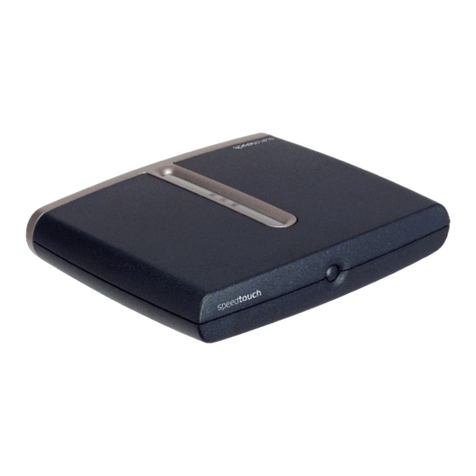
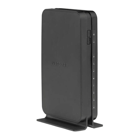
Technicolor - Thomson DCW615 User manual

010011110101110110111000
101010101011100110111011
10110110101100101111110
11010110110110011100111
011101001110111101101101
10101010101101101110010
0101101011101010011010
10111010110111100110100
0100101101001111010111
101010101011100110111011
10110110101100101111110
11010110110110011100111
011101001110111101101101
10101010101101101110010
0101101011101010011010
10111010110111100110100
010011110101110110111000
101010101011100110111011
10110110101100101111110
11010110110110011100111
011101001110111101101101
10101010101101101110010
Wireless Cable
Gateway
16096620 DCW615/25. 00 Cover 6/26/03, 10:45 AM1

CAUTION: Disconnect
power before servicing.
CAUTION: To ensure reliable operation and to prevent
overheating, provide adequate ventilation for this modem and
keep it away from heat sources. Do not locate near heat
registers or other heat-producing equipment. Provide for free
air flow around the cable modem and its power supply.
CABLE INSTALLER:
This reminder is provided to call your attention to Article 820-40 of the National Electrical Code
(Section 54 of the Canadian Electrical Code, Part 1) which provides guidelines for proper grounding
and, in particular, specifies that the cable ground shall be connected to the grounding system of the
building as close to the point of cable entry as practical.
DOCSIS compliant
This product was designed according to Data Over Cable Service Interface Specifications.
It will operate on any DOCSIS-compliant Hybrid Fiber Coax (HFC) cable system and offers DOCSIS
Baseline Privacy to promote secure Internet transactions.
Power cord Requirement
This product must be operated with the supplied line cord or with a line cord meeting IEC227 H03
VV-F or IEC227 H03 VVH2-F having conductors with a cross-sectional area not less than .75mm2.
Operating Information
Operating Temperature: 0˚ - 40˚ C (32˚ - 104˚ F)
Storage Temperature: -30˚ to 65˚ C
Power Pack
The power pack is intended to serve as mains disconnect device and so allows to turn off the cable
modem. This pack shall be easily accessible in an emergency
If you purchased this product at a retail outlet, please read the following:
Product Registration
Please fill out the product registration card that came with this product and return it immediately. Returning the card
allows us to contact you if needed.
Keep your sales receipt to obtain warranty parts and service and for proof of purchase. Attach it here and record the
serial and model numbers in case you need them. The numbers are located on the back of the product.
Model No. ____________________________________ Serial No _____________________________________________
Safety Information
16096620 DCW615/25. 00 Cover 6/26/03, 10:45 AM2

Table of Contents
1
Chapter 1: Overview and Setup
Introduction ................................................................................... 4
Wireless Cable Gateway Features .......................................................................... 4
What’s on the CD-ROM ............................................................................................ 5
Computer Requirements ........................................................................................... 6
Wireless Cable Gateway Overview............................................... 6
Contact Your Local Cable Company ...................................................................... 7
System Overview ........................................................................... 8
Your PC: Installing a PC Network Card ................................................................ 8
Your PC: Installing a TCP/IP Stack ......................................................................... 9
Your PC: Configuring DHCP on a TCP/IP Stack on a PC.................................10
Configuring Windows Me PCs .............................................................................. 11
Configuring Windows 2000 PCs ......................................................................... 12
Configuring Windows XP PCs .............................................................................. 12
Chapter 2: Connections and Setup
Connecting Your Devices ............................................................ 13
Ethernet Connection ............................................................................................... 13
USB Connecton ........................................................................................................ 13
Connecting the Cable Modem Using Windows Me for USB Connection 14
Activating the Wireless Cable Gateway.................................... 15
Initialization .............................................................................................................. 15
Buttons ....................................................................................................................... 16
Reset Switch ............................................................................................................. 17
Software Download Indicator .............................................................................. 17
Mandatory User Configuration .................................................. 18
TOC to be updated
16096620 DCW615/25. 00 TOC 6/26/03, 10:45 AM1

Table of Contents
2
Chapter 3: Networking and Advanced Settings
Advanced User Configuration .................................................... 10
Three Networking Modes ...................................................................................... 20
Status Web Page Group .............................................................. 21
Software Web Page ..................................................................................................21
Connection Web Page .............................................................................................21
Security Web Page .................................................................................................. 22
Diagnostics Web Page ............................................................................................ 22
Basic Web Page Group ................................................................ 23
Setup Web Page ....................................................................................................... 23
DHCP Web Page ....................................................................................................... 24
Advanced Web Page Group ........................................................ 25
Options Web Page ................................................................................................... 25
IP Filtering Web Page ............................................................................................. 26
MAC Filtering Web Page ........................................................................................ 26
Port Filtering Web Page ......................................................................................... 26
Forwarding Web Page ............................................................................................ 27
Port Triggers Web Page .......................................................................................... 27
DMZ Host Web Page ............................................................................................... 28
Routing Informaton Protocol Setup ................................................................... 28
Firewall Web Pages Group.......................................................... 29
Time of Day ............................................................................................................... 29
Web Filter Web Page .............................................................................................. 29
Event Log Web Page ............................................................................................... 30
Parental Control Web Pages Group .................................................................... 30
Wireless Web Pages Group ......................................................... 31
16096620 DCW615/25. 00 TOC 6/26/03, 10:45 AM2

Table of Contents
3
Enable Web Page ......................................................................................................31
Basic Web Page .........................................................................................................31
Privacy Web Page .....................................................................................................31
Advanced Web Page ............................................................................................... 32
Access Control Page................................................................................................ 32
Determining Wifi MAC address ................................................. 34
Chapter 4: Additional Information
Troubleshooting ........................................................................... 35
Front of the Unit (DCW615) ..................................................... 36
Front of the Unit (DCW625/TCW690) ..................................... 37
Back of the Unit (DCW615) ...................................................... 38
Back of the Unit (DCW625/TCW690) ...................................... 39
Detailed Explanation of Jacks.................................................... 40
Care and Cleaning ....................................................................... 41
Service Information .................................................................... 41
FCC Declaration of Conformity and Industry
Canada Information .................................................................... 42
Additional FCC Information ....................................................... 43
Product Specifications ................................................................ 45
TOC to be updated
16096620 DCW615/25. 00 TOC 6/26/03, 10:45 AM3

Chapter 1: Overview and Setup
Illustrations contained in this document are for representation only.
4Chapter 1
Introduction
Wireless Cable Gateway Features
Thank you for purchasing the Wireless Cable Gateway. This device delivers the highest
performance in data over cable technology. Ideal for home and small business users, this easy-to-
use communication device offers reliable connectivity as well as remarkable data transfer rates—
up to 600 times faster than a 56K dial-up modem. Once the gateway is activated, you are online
to enjoy real-time 3D animation, video conferencing, and perform other data intensive tasks.
The Wireless Cable Gateway provides high-speed, reliable and secure transport capabilities and is
designed with DOCSIS upgrade ability for both DOCSIS 1.0 and 1.1. The gateway offers anti-
spoofing functions, resulting in greater subscriber privacy and higher system availability.
Advanced features such as HomePNA2.0, WLAN IEEE 802.11b, NAT, Firewall, VPN pass through and
CableHome are also available now and can be configured.
16096620 DCW615/25. 01 Oview 6/26/03, 10:45 AM4

Chapter 1 5
Chapter 1: Overview and Setup
What’s on the CD-ROM
If you connect a PC using the USB port on your gateway, you’ll need the USB drivers found on the
CD-ROM.
CD-ROM Contents:
•Electronic copy of this user’s guide (.pdf format)
•Adobe Acrobat Reader — application you can load to read .pdf format, if you don’t have it
loaded already
•USB drivers — required if connecting by USB
16096620 DCW615/25. 01 Oview 6/26/03, 10:45 AM5

6Chapter 1
Chapter 1: Overview and Setup
Computer Requirements
•USB 1.0 or 1.1 (PC only), Ethernet (10/100), 802.11b, or HPNA 1.0 or 2.0 connectivity
•ATCP/IP network protocol for each machine
•Anetwork cable with RJ-45 connector for Ethernet connection
• Microsoft Internet Explorer 4.0 or later, or Netscape Navigator 4.0 or later. (5.0 and 4.7 or
later, respectively, are strongly recommended.)
•Windows Me, 2000, or XP for USB
Wireless Cable Gateway Overview
Cable Internet Service Requirements
•Cable company that offers DOCSIS-compliant Internet services
What the Wireless Cable Gateway Does
The Digital Wireless Cable Gateway serves as a two-way high-speed bridge between your personal
computer and a cable Internet Service Provider (ISP). It converts information that originates from
the Internet or your computer into electronic messages that can be transported over the same
wires your cable company uses to transport video signals.
What the Wireless Cable Gateway Needs to Do Its Job
•The Right Cable Company: Make sure your cable company provides data services that use
cable TV industry-standard DOCSIS technology.
•The Internet Service Provider (ISP): Your cable company provides you access to an Internet
Service Provider (ISP). The ISP is your gateway to the Internet. It provides you with a pipeline
to access Internet content on the World Wide Web (WWW).
Computer Internet
Wirelesss Cable Gateway Cable Company
HPNA
WLAN
Power
Test
USB
Full/Col
100/10
Link/Act
Receive
Send
Ready
Link/Act Cable Modem
1 2 3 4
16096620 DCW615/25. 01 Oview 6/26/03, 10:45 AM6

Chapter 1 7
Chapter 1: Overview and Setup
Check with your cable company to make sure you have everything you need to begin; they’ll
know if you need to install special software or re-configure your computer to make your
cable Internet service work for you.
Contact Your Local Cable Company
You will need to contact your cable company to establish an Internet account before you can use
your gateway. You should have the following information ready (which you will find on the
sticker on the gateway) :
•The serial number
•The model number
•The Media Access Control (MAC) address
Record your information here:
Serial Number: _________________________
Model Number: _________________________
MAC Address: __________________________
Please verify the following with the cable company:
S.N.
MODEL:
MAC:
XXXXXXXXXXXXXX
DCWXXX
009064XXXXXX
•The cable service to your home supports DOCSIS-compliant two-way modem access.
•Your Internet account has been set up.
•You have a cable outlet near your PC and it is ready for cable modem service.
Note: It is important to supply power to the modem at all times. Keeping your modem plugged in will keep it
connected to the Internet. This means that it will always be ready when you are. To disconnect your computer
from the Internet, use the ON/OFF button to put the modem in standby mode.
Important Information
Your cable company should always be consulted before installing a new cable outlet. Do not
attempt any rewiring without contacting your cable company first.
16096620 DCW615/25. 01 Oview 6/26/03, 10:45 AM7

8Chapter 1
Chapter 1: Overview and Setup
System Overview
The Wireless Cable Gateway is connected between your cable company and the PCs within your
home, as pictured previously in the Wireless Cable Gateway Overview. The connection to the cable
company is made by a coaxial cable, and is referred to as the WAN (Wide Area Network) side of
your Wireless Cable Gateway. The connections to your PCs are made by your choice of several
standard home networking methods: Ethernet, USB, or 802.11g Wireless. These are referred to as
the LAN (Local Area Network) side of your Wireless Cable Gateway. Multiple PCs can use any or all
of the LAN side connections simultaneously to share your single cable company connection, up to
a maximum of 254 PCs total.
Unlike a simple hub or switch, the gateway’s setup consists of more than simply plugging
hardware together. You’ll need to configure your networked PCs to accept the IP addresses the
gateway assigns them (if applicable), and you will also need to configure the gateway with
settings provided by your cable company.
This installation guide takes you through all the necessary steps for easy installation. Please refer
to the troubleshooting section for any improper behavior.
Even if you consider to use the gateway in a wireless mode only, it is highly recommended to
perform all the settings through a wired connection: USB or Ethernet first.
• If you intend to connect the Gateway though USB, please go to Chapter 2, USB Connection,
page XX.
• If you intend to connect the Gateway though Enternet, please go to Chapter 2, Ethernet
Connection, page XX.
•If you already have a network card, follow the next section.
Your PC: Installing a PC Network Card
If your PC does not already support Ethernet or USB, you must install a network interface card.
Following is an example setup procedure:
1. Install an Ethernet card on your motherboard, following the card’s directions.
2. Power up your PC and follow the Add New Hardware Wizard’s instructions to install the
driver. When asked to restart your computer at the end of the installation, click Yes.
3. After restarting the system, right-click My Computer on the desktop, select Properties, click
the Device Manager tab, and then double-click Network adapters to confirm that the
Ethernet driver is properly installed.
16096620 DCW615/25. 01 Oview 6/26/03, 10:45 AM8

Chapter 1 9
Chapter 1: Overview and Setup
Your PC: Installing a TCP/IP Stack
Follow these instructions to install the TCP/IP protocol stack on one of your PCs only after a
network card has been successfully installed inside the PC. These instructions are for Windows Me.
For TCP/IP setup under Windows NT, 2000, and XP, refer to your Windows documentation.
1. Click the Start button. Choose Settings and then Control Panel.
2. Double-click on the Network icon to bring up your
Network window. Select the Configuration tab.
3. Click the Add button.
4. Double-click on Protocol.
Fig. 1
5. Highlight Microsoft under the list of manufacturers.
6. Find and double-click TCP/IP in the list to the right (see
Figure 9).
Fig. 2
16096620 DCW615/25. 01 Oview 6/26/03, 10:45 AM9

10 Chapter 1
Chapter 1: Overview and Setup
Fig. 3
Fig. 4
7. After a few seconds, the main Network window will appear.
The TCP/IP Protocol should now be listed.
8. Click the OK button again. Windows may ask you for the
original Windows installation disk or additional files. Supply
them by pointing to the correct file location, e.g., D:\win9x,
c:\windows\options\cabs, etc. (if “D” is the letter of your
CD-ROM drive).
9. Windows will ask you to restart the PC. Click the Yes
button.
The TCP/IP installation is now complete.
Your PC: Configuring DHCP on a TCP/IP Stack on a PC
These instructions will help you configure each of your computers to be able to communicate
with the gateway to obtain an IP (or TCP/IP) address automatically (called DHCP, Dynamic Host
Configuration Protocol).
Find out which operating system your computer is running by clicking the Start button and then
going to the Settings option. Then click Control Panel and double-click the System icon. If your
Start menu doesn’t have a Settings option, you’re running Windows XP. Click the Cancel button
when done.
You may need to do this for each computer you are connecting to the gateway.
16096620 DCW615/25. 01 Oview 6/26/03, 10:45 AM10

Chapter 1 11
Chapter 1: Overview and Setup
Important: These instructions apply only to Windows Me, 2000, or XP machines. For TCP/IP setup
under Windows NT, see your Windows manual. By default Windows 2000, Me, and XP have TCP/
IP installed and set to obtain an IP address automatically.
The next few pages tell you, step by step, how to configure your network settings, based on the
type of Windows operating system you are using. Make sure that an Ethernet card or adapter has
been successfully installed in each PC you want to configure.
Configuring Windows Me PCs
1. Go to the Network screen by clicking the Start button. Click
Settings and then Control Panel. From there, double-click
the Network icon.
2. On the Configuration tab, select the TCP/IP line for the
applicable Ethernet adapter. Do not choose a TCP/IP entry
whose name mentions DUN, PPPoE, VPN, or AOL. If TCP/IP
appears by itself, select that line. (If there is no TCP/IP line
listed, you need to install a TCP/IP stack). Refer to Your PC:
Installing a TCP/IP Stack. Click the Properties button.
3. Click the IP Address tab. Select Obtain an IP address
automatically.
4. Now click the Gateway tab to ensure that the Installed
gateway field is left blank. Click the OK button.
5. Click the OK button again. Windows may ask you for the
original Windows installation disk or additional files. Supply
them by pointing to the correct file location, e.g., D:\win9x,
c:\windows\options\cabs, etc. (if “D” is the letter of your
CD-ROM drive).
6. Windows may ask you to restart your PC. Click the Yes
button. If Windows does not ask you to restart, restart your
computer anyway.
Fig. 6
Fig. 5
16096620 DCW615/25. 01 Oview 6/26/03, 10:45 AM11

12 Chapter 1
Chapter 1: Overview and Setup
Configuring Windows 2000 PCs
1. Go to the Network screen by clicking the Start button. Click Settings and then Control Panel.
From there, double-click the Network and Dial-up Connections icon.
2. Select the Local Area Connection icon for the applicable Ethernet adapter (it’s usually the
first Local Area Connection listed). Double-click the Local Area Connection. Click the
Properties button.
3. Select Internet Protocol (TCP/IP), and click the Properties button.
4. Select Obtain an IP address automatically. Once the new window appears, click the OK
button. Click the OK button again to complete the PC configuration.
5. Restart your computer.
Configuring Windows XP PCs
The following instructions assume you are running Windows XP with the default interface. If you
are using the Classic interface (where the icons and menus look like previous Windows versions),
please follow the instructions for Windows 2000.
1. Go to the Network screen by clicking the Start button and then Control Panel. From there,
double-click the Network Internet Connections icon and then the Network Connections
icon.
2. Select the Local Area Connection icon for the applicable Ethernet adapter (it’s usually the
first Local Area Connection listed). Double-click the Local Area Connection. Click the
Properties button.
3. Select Internet Protocol (TCP/IP), and click the Properties button.
4. Select Obtain an IP address automatically. Once the new window appears, click the OK
button. Click the OK button again (or the Close button if any settings were changed) to
complete the PC configuration.
5. Restart your computer.
16096620 DCW615/25. 01 Oview 6/26/03, 10:45 AM12

Chapter 2: Connections and Setup
Chapter 2 13
Illustrations contained in this document are for representation only.
Connecting Your Devices
Ethernet Connection
1. Before you begin, make sure that all of your hardware is powered off, including the gateway,
PCs, hubs, and switches.
2. Connect one end of an Ethernet cable to one of the Ethernet ports on the back of the
gateway and the other end to a standard port on a network device, e.g., a PC, print server,
hub, or switch.
3. Connect the coaxial cable from the wall to the CABLE jack on the back of the gateway.
4. Connect the power supply cable to the Power jack on the back of the gateway, then plug the
supplied power cable into an AC power outlet. Go to section, Activating the Wireless Cable
Gateway, page 15.
USB Connection
The cable modem CD included with your modem contains the drivers and other information you
need to install your cable modem. Follow instructions 1 through 5 to connect the cable modem to
the USB port on your computer. Instructions must be followed in the order they appear.
1. Connect one end of the coaxial cable to the cable connection in the wall. Attach the other
end of the coaxial cable to the connector on the cable modem labeled “CABLE” (Fig. 2) on
page 8
2. Insert the plug from the AC power supply into the power AC jack on cable modem and the
two-prong plug into the AC outlet.
3. Insert the supplied cable modem CD-ROM. Wait momentarily fo rthe cable modem CD
window display.
4. Close all open appplications and dialog boxes, including the cable modem CD window.
Note: Open applications may interfere with your cable modem installation.
5. Connect one end of the USB cable to the USb port located on the back of your conmputer.
Connect the other end of the USB cable to the USB port on the cable modem’s back panel.
Note: Use only the power supply that accompanied this unit. Using pther power supplies
may damage the unit. Next, you need to install the USB drivers for your operation system,
(Installation for Windows Me is described hereafter:)
16096620 DCW615/25. 02 Connect 6/26/03, 10:45 AM13

14 Chapter 2
Chapter 2: Connections and Setup
Connecting the Cable Modem Using Windows Me for USB Connection
6. Windows Me will briefly disply the “found New Hardware
Wizard,” and automatically proceed to the “add New
Hardware Wizard” (Fig. 7).
Choose the Automatic search for a better driver
(Recoomend)” otpion, and click “Next.”
Note: If Windwos Me does not recognize the cable
modem’s presence, i.e., the “add New hardware Wizard”
did not automatically appear, your BIOS settings may not
permit USB and/or Plug-and-Play devices. Pelase contact
your comptuer’s customer service department.
Fig. 8
Fig. 7
7. The automatic search should find and install the driver for
the “RCA or Thomson USB Cable Modem” (Fig.8). Click on
“Finish’ to complete the process.
8. When the “System Settings Change” window appears, click
“Yes” to restart your computer (Fig. 9).
9. The Thomson cable modem installation is now complete. To validate a proper installation, perform
the following instructions.
• Click on “Start” icon in the lower left-hand corner of your screen.
•Select “Settings,” followed by “Control Panel.” The “Control Panel” window appears.
•Double-click on the “System” icon, and select the “Device Manager.”
Fig. 9
16096620 DCW615/25. 02 Connect 6/26/03, 10:45 AM14

Chapter 2 15
Chapter 2: Connections and Setup
•Scroll down the list until you come to “Network Adapters.” Double-click on “Network
Adapters.”
•The “RCA or Thomson USB Cable Modem” should exist. If ‘RCA or Thomson USB Cable
Modem” does not exist, the cable modem was NOT installed correctlly. Uninstall the drivers
and start the process again.
Activating the Wireless Cable Gateway
Initialization
Turn on the gateway’s POWER switch (DCW615) or the ON/OFF button on the front (DCW625/
TCW690). The Power indicator on the front of the unit comes on.
Initialization Modes
After you install the cable modem and turn it on for the first time (and each time the modem is
reconnected to the power), it goes through five steps before it can be used. Each of these steps is
represented by a different pattern of flashing lights on the front of the modem.
Note: All indicators flash once prior to the initialization sequence.
InternetOn/Off
Cable
Activity Cable
Link
Message PCLink Internet
Internet On/Off
Cable
Activity Cable
Link
Message PC Link Internet
x
1. Tuning – The cable modem is functional and searching for
a downstream cable modem service channel on your cable
system.
2. Ranging – The modem is now tuned to a downstream cable
modem channel and can now receive data. Now it searches
for an upstream channel so that it can send data.
3. Connecting – The cable modem is now commun-icating
start-up data both down-stream and upstream.
The cable company is establishing IP connectivity with your
modem.
InternetOn/Off
Cable
Activity Cable
Link
Message PCLink Internet
Internet On/Off
Cable
Activity Cable
Link
Message PC Link Internet
x
x
InternetOn/Off
Cable
Activity Cable
Link
Message PCLink Internet
Internet On/Off
Cable
Activity Cable
Link
Message PC Link Internet
x
x
x
16096620 DCW615/25. 02 Connect 6/26/03, 10:45 AM15

16 Chapter 2
Chapter 2: Connections and Setup
4. Configuring – The cable modem received its IP address and
is downloading its configuration file from the Internet
Service Provider (ISP).
InternetOn/Off
Cable
Activity Cable
Link
Message PCLink Internet
Internet On/Off
Cable
Activity Cable
Link
Message PC Link Internet
x
x
xx
InternetOn/Off
Cable
Activity Cable
Link
Message PCLink Internet
Internet On/Off
Cable
Activity Cable
Link
Message PC Link Internet
x
x
xx
x
5. Registering – The cable modem configuration is complete.
It is registering its “as-configured” settings with your Cable
Operator. Once complete, the POWER (INTERNET)*, PC LINK,
and CABLE (CABLE ACTIVITY)* indicators stop flashing and
remain on.
Internet On/Off
Cable
Activity Cable
Link
Message PC Link Internet
INTERNET* – Indicates whether the Internet Connection is active.
CABLE LINK* – Indicates the status of your cable connection. The light is off when no cable
connection is detected and fully lit when the modem is registered with the network and data can
be sent.
PC LINK – Indicates whether the connection between the computer and the modem is active
(ready to transmit/receive) or actually transmitting/receiving. The light is off when no carrier is
present (or the modem is in standby mode), on when the carrier is present but there’s no transmit/
receive activity, and flashing when there is transmit/receive activity.
Buttons
INTERNET ON/OFF* – Turns the Internet connection ON and OFF for additional security. In
OFF mode, the CABLE ACTIVITY LED is also disabled.
Important: Do not press this button when transmitting data over the Internet. The
information will be lost and your Internet connection disabled.
Indicators – Operational Mode
Legend Off On Flashing
X
16096620 DCW615/25. 02 Connect 6/26/03, 10:45 AM16

Chapter 2 17
Chapter 2: Connections and Setup
InternetOn/Off
Cable
Activity Cable
Link
Message PCLink Internet
Internet On/Off
Cable
Activity Cable
Link
Message PC Link Internet
x
x
xx
x
USB* – Indicates the PC-LINK status for the USB connection
ETHERNET* – Indicates the PC-LINK status for the Ethernet connection
Note: If all of the lights are flashing sequentially, it means the cable modem is
automatically updating its system software. Please wait for the lights to stop flashing. You
cannot use your modem during this time. Do not remove the power supply or reset the
cable modem during this process.
* Actual button or LED names may vary per model.
Reset Switch
•Factory Default Reset – Unplug the modem from the AC power. Press and hold the reset
switch while plugging the modem into AC power. Continue holding the switch. Release the
switch when all lights come on (about 6 seconds). This will return the modem to a factory
“out of box” condition. This should only be done if the cable modem has been taken out of
service in one location and is being reconnected to a different service, or if instructed to
do so by your cable company.
Reset switch
3VDC800mAETHERNETRESET
USB CABLE
The reset switch can be found behind a “toothpick
hole” on the back panel. It performs two functions:
•Basic Reset – Press and release the switch to make
it perform the same function as disconnecting the
power from the modem. It will start up again in
Initialization Mode, see page 24.
Software Download Indicator
Software downloading or update in progress. Lights flash
sequentially from top to bottom.
Legend Off On Flashing
X
16096620 DCW615/25. 02 Connect 6/26/03, 10:45 AM17

18 Chapter 2
Chapter 2: Connections and Setup
Mandatory User Configuration
This feature allows you to configure the gateway to function in your network and gain access to
the Internet through your cable company. Your ISP may require the use of a Host Name and
Domain Name. You will need to get the setup information from your ISP. If you do not have this
information, please contact your ISP before proceeding.
The instructions from your ISP will tell you how to set up your PC for Internet access.
Also, you must disable any Internet log-on software (such as Ivasion Winpoet or Enternet 300)
and any firewall software (such as ZoneAlarm and Watchdog) on all of your PCs.
Fig. 10
1. Open your web browser. (It’s all right if you get an error
message at this point. Continue following these directions).
Enter http://192.168.100.1 in the browser’s Address field if
your gateway is in the CM Mode, or http://192.168.0.1 if it
is in the RG or CH Mode. Press the Enter key.
2. An Enter Network Password window appears (for Windows
XP users, the screen may look different). Leave the User
Name field empty, and enter admin in lowercase letters in
the Password field (admin is the default password). Then,
click the OK button.
3. If you are in CM or CH mode, the Basic webpage group
hyperlink is visible. In this case, select the Basic Setup web
page by using the hyperlinks in the sidebar at the left of the
screen. Otherwise, skip to step 4. Based on the setup
instructions from your cable company, you may need to
enter the following information.
LAN IP Address: The value for the gateway’s local IP address
is shown on the Setup screen. The default value is
192.168.0.1. We recommend you keep this setting.
Host Name and Domain Name: These fields allow you to
provide a host name and domain name for the gateway.
These fields are usually left blank. If requested by your cable
company, complete these two fields.
Fig. 11
16096620 DCW615/25. 02 Connect 6/26/03, 10:45 AM18
This manual suits for next models
1
Table of contents
Other Technicolor - Thomson Gateway manuals
Popular Gateway manuals by other brands

Comnet
Comnet NetWave NW7 Installation and operation manual

Aluratek
Aluratek CDW530AM user guide

Panasonic
Panasonic KX-TDA3480 Programming guide

KSB
KSB AmaControl INT 600 DM Supplementary Operating Manual

ZyXEL Communications
ZyXEL Communications Prestige 661H Series quick start guide

Dialogic
Dialogic 4000 Series reference guide