manuals.online logo
Brands
  1. Home
  2. •
  3. Brands
  4. •
  5. Technics
  6. •
  7. Amplifier
  8. •
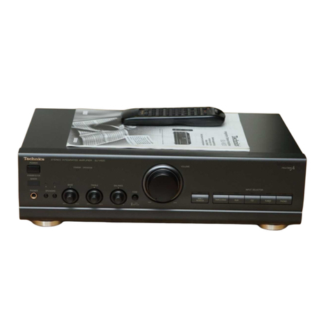
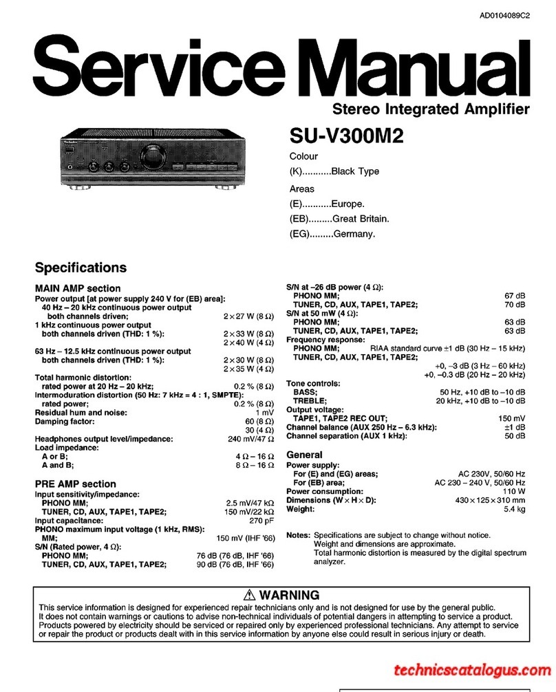
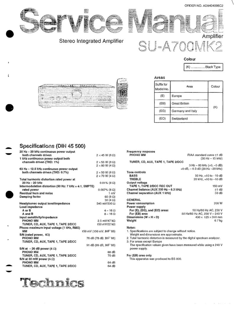
  9. Technics SU-A900 User manual

Technics SU-A900 User manual

Other manuals for SU-A900

2

This manual suits for next models

1

Other Technics Amplifier manuals

Technics SU-X933 User manual

Technics

Technics SU-X933 User manual

Technics SU-Z35 User manual

Technics

Technics SU-Z35 User manual

Technics SU-Z15 - SERVICE User manual

Technics

Technics SU-Z15 - SERVICE User manual

Technics SE-A7 User manual

Technics

Technics SE-A7 User manual

Technics SA-EH560 User manual

Technics

Technics SA-EH560 User manual

Technics SU-V8 User manual

Technics

Technics SU-V8 User manual

Technics SU-C1010 User manual

Technics

Technics SU-C1010 User manual

Technics SU-V4X User manual

Technics

Technics SU-V4X User manual

Technics SU-V900 User manual

Technics

Technics SU-V900 User manual

Technics SU-G30 User manual

Technics

Technics SU-G30 User manual

Technics SECH-515-A User manual

Technics

Technics SECH-515-A User manual

Technics SU-X502 User manual

Technics

Technics SU-X502 User manual

Technics su-v909 User manual

Technics

Technics su-v909 User manual

Technics SU-V500M2 User manual

Technics

Technics SU-V500M2 User manual

Technics SU-V620 - SERVICE User manual

Technics

Technics SU-V620 - SERVICE User manual

Technics SU-C2000 User manual

Technics

Technics SU-C2000 User manual

Technics SE-CA10 - service User manual

Technics

Technics SE-CA10 - service User manual

Technics SU-R1 User manual

Technics

Technics SU-R1 User manual

Technics SU-C550 User manual

Technics

Technics SU-C550 User manual

Technics SU-C800UM2 User manual

Technics

Technics SU-C800UM2 User manual

Technics SU-V660 User manual

Technics

Technics SU-V660 User manual

Technics SE-HD350 User manual

Technics

Technics SE-HD350 User manual

Technics SU-X820 User manual

Technics

Technics SU-X820 User manual

Technics SU-V4 User manual

Technics

Technics SU-V4 User manual
Popular Amplifier manuals by other brands

Magnat Audio EDITION FOUR Owner's manual/warranty document

Magnat Audio

Magnat Audio EDITION FOUR Owner's manual/warranty document

Inter-m PA-2000A Operation manual

Inter-m

Inter-m PA-2000A Operation manual

Yamaha TX6n owner's manual

Yamaha

Yamaha TX6n owner's manual

Peavey TNT 150 user guide

Peavey

Peavey TNT 150 user guide

Bosch LBB 1903/10 Installation and user instructions

Bosch

Bosch LBB 1903/10 Installation and user instructions

Avocent Emerge DA1200D Installer/user guide

Avocent

Avocent Emerge DA1200D Installer/user guide

Redgum RGi35 operating instructions

Redgum

Redgum RGi35 operating instructions

Cambridge Audio AXA25 user manual

Cambridge Audio

Cambridge Audio AXA25 user manual

Alpine MRP-M200 owner's manual

Alpine

Alpine MRP-M200 owner's manual

Technical Pro H1502UrBT user manual

Technical Pro

Technical Pro H1502UrBT user manual

FMS EMGZ307 operating manual

FMS

FMS EMGZ307 operating manual

Racal Instruments 5601 user manual

Racal Instruments

Racal Instruments 5601 user manual

Valcom V-1094A Technical specifications

Valcom

Valcom V-1094A Technical specifications

Cambridge Audio 851D user manual

Cambridge Audio

Cambridge Audio 851D user manual

QSC 3800 Specifications

QSC

QSC 3800 Specifications

NAD C300 owner's manual

NAD

NAD C300 owner's manual

Rotel RMB-1077 owner's manual

Rotel

Rotel RMB-1077 owner's manual

Peavey Monitor 300 Series operating guide

Peavey

Peavey Monitor 300 Series operating guide

manuals.online logo
manuals.online logoBrands
  • About & Mission
  • Contact us
  • Privacy Policy
  • Terms and Conditions

Copyright 2025 Manuals.Online. All Rights Reserved.

Technics
Stereo
Integrated
Amplifier
SU-A900
SU-A800
Operating
Instructions
Dear
Customer
Thank
you
for
purchasing
this
product.
For
optimum
performance
and
safety,
please
read
these
instructions
carefully.
These
operating
instructions
are
applicable
to
models
SU-A900
and
SU-A800.
Contents
©
Accessories
.......
cece
cee
eens
2
e
Remote
Control
Transmitter..............
1i
¢
Caution
for
AC
mains
lead
e
Remote
Control
Operation................
12
(For
United
Kingdom).
................
000000
3
©
Suggestions
for
Safety...................
14
e
Connections
.....................
cece
ee
4
©
Technical
Specifications
.................
15
e
Front
Panel
Controls
and
Functions
......
7
e
Maintenance.......................000
eee
15
e
Listening
to
Sound.......................
8
©
Troubleshooting
Guide
.........
Back
cover
©
Recording
.............
cece
cece
eee
10
For
areas
except
United
Kingdom,
Europe,
Australia
and
N.Z.
CAUTION:
:
The
AC
voltage
differs
according
to
the
area.
Be
sure
to
set
the
proper
voltage
in
your
area
before
use.
(For
details,
please
refer
to
page
5.)
e
AC
power
supply
cord
(For
United
Kingdom)
(For
Australia
and
N.Z.)
*
Batteries
©
Power
plug
adaptor
(Not
supplied
for
United
Kingdom,
Europe,
Australia
and
N.Z.)
Caution
for
AC
mains
lead
(For
United
Kingdom)
(“EB"
area
code
model
only)
For
your
safety,
please
read
the
following
text
care-
fully.
This
appliance
is
supplied
with
a
moulded
three
pin
mains
plug
for
your
safety
and
convenience.
A5-ampere
fuse
is
fitted
in
this
plug.
Should
the
fuse
need
to
be
replaced
please
ensure
that
the
replacement
fuse
has
a
rating
of
5-ampere
and
that
it
is
approved
by
ASTA
or
BSI
to
BS
1362.
Check
for
the
ASTA
mark
@
or
the
BSI
mark
Y
on
the
body
of
the
fuse.
If
the
plug
contains
a
removable
fuse
cover
you
must
ensure
that
it
is
refitted
when
the
fuse
is
replaced.
if
you
lose
the
fuse
cover
the
plug
must
not
be
used
until a
replacement
cover
is
obtained.
A
replacement
fuse
cover
can
be
purchased
from
your
local
dealer.
CAUTION!
IF
THE
FITTED
MOULDED
PLUG
!S
UN-
SUITABLE
FOR
THE
SOCKET
OUTLET
IN
YOUR
HOME
THEN
THE
FUSE
SHOULD
BE
REMOVED
AND
THE
PLUG
CUT
OFF
AND
DISPOSED
OF
SAFELY.
THERE
IS
A
DANGER
OF
SEVERE
ELEC-
TRICAL
SHOCK
IF
THE
CUT
OFF
PLUG
IS
INSERTED
INTO
ANY
13-AMPERE
SOCKET.
If
a
new
plug
is
to
be
fitted
please
observe
the
wiring
code
as
shown
below.
If
in
any
doubt
please
consult
a
qualified
electrician.
IMPORTANT
The
wires
in
this
mains
lead
are
coloured
in
accor-
dance
with
the
following
code:
Blue:
Neutral
Brown:
Live
As
the
colours
of
the
wires
in
the
mains
lead
of
this
appliance
may
not
correspond
with
the
coloured
markings
identifying
the
terminals
in
your
plug,
pro-
ceed
as
follows:
The
wire
which
is
coloured
BLUE
must
be
connected
to
the
terminal
in
the
plug
which
is
marked
with
the
-
letter
N
or
coloured
BLACK.
The
wire
which
is
coloured
BROWN
must
be
con-
nected
to
the
terminal
in
the
plug
which
is
marked
with
the
letter
L
or
coloured
RED.
Under
no
circumstances
should
either
of
these
wires
be
connected
to
the
earth
terminal
of
the
three
pin
plug,
marked
with
the
letter
E
or
the
Earth
Symbol
L
Before
use
Remove
the
connector
cover
as
follows.
How
to
replace
the
fuse
1.
Remove
the
fuse
cover
with
a
screwdriver.
Connections
To
connect
to
each
terminal
Make
connections
to
each
component
in
the
system
by
using
stereo
connection
cables
(not
included).
Stereo
connection
cable
White
(L)
Red
(R)
GOO
O=
®
“PHONO”
terminals
Connect
to
a
turntable.
GND
DO
Turntable
(not
included)
®
U
M
“GND”
terminal
This
terminal
is
for
use
with
a
turntable
which
has
a
ground
wire.
“TUNER”
terminals
Connect
to
a
tuner.
Tuner
(not
included)
SPEAKERS
Cooling
fan
(See
page
5.)
©Cep"
terminals)
Connect
to
a
compact
disc
player.
©
Compact
disc
player
(not
included)
e
OUT
D
Q
GS
~
AU
=
©)
“AUX”
terminals
Connect
to
a
component
such
as
a
video
disc
player
(audio
only
connectable),
etc.
Video
disc
player
(not
included)
AUDIO
OUT
9
Ọ
LJ
Æ
“TAPE
2”
terminals
Connect
to
a
second
tape
deck
(Tape
deck
2)
or
a
graphic
equalizer,
etc.
Tape
deck
2
(not
included)
REC(IN)
PLAY(OUT}
œŒ
Q
©
C
“TAPE
1”
terminals
Connect
to
a
first
tape
deck
(Tape
deck
1)
or
a
digital
compact
cassette
deck
(DCC),
atc.
Tape
deck
1
(not
included)
@
(“REMOTE
CONTROL
OUT”
terminal
This
terminal
can
be
used
only
with
Technics
tape
deck
and
com-
pact
disc
player
which
have
the
appropriate
remote
control
ter-
minal.
(Consult
your
dealer
for
details.)
Proper
connection
with
remote
control
connection
cables
will
allow
control
of
some
functions
from
this
unit’s
remote
control
transmitter.
(See
pages
12—13
for
details.)
Connect
to
a
tape
deck
and/or
compact
disc
player
as
shown
below,
If
a
tape
deck
is
not
being
used,
the
compact
disc
player
can
be
connected
directly
(dotted
line).
This
unit
REMOTE
@
CONTROL
OUT
Connection
cable
for
remote
control
(included
with
tape
deck)
Tape
deck
(not
included)
REMOTE
Q
CONTROL
;
2 =
Connection
cable
for
remote
control
(Included
with
compact
disc
r=-
Compact
disc
player
A
(not
included)
REMOTE
=
For
a
compact
disc
player
with
a
remote
control
sensor,
the
above
connection
is
not
necessary.
To
set
the
power
voltage
For
areas
except
United
Kingdom,
Europe,
Australla
and
N.Z.
CoE,
CODCOD
Set
the
voltage
selector
to
"110
V—127
V"
or
“220
V-240
V"
according
to
the
area
in
which
the
unit
will
be
used.
{Use
a
minus
(—)
screwdriver]
Note:
Note
that
this
unit
will
be
seriously
damaged
if
this
setting
is
not
made
correctly.
There
is
no
cooling
fan
for
some
countries.
The
coofing
fan
operates
at
high
power
output
levels
only.
CONNECTIONS
n.s
One
pair
of
speakers
can
be
connected
to
the
“A”
terminals
of
this
unit
and
one
pair
to
the
“B”
terminals,
or
only
one
pair
of
bi-
wired
speakers
can
be
connected
to
ail
terminals.
To
connect
main
and/or
second
speakers
Main
(A)
speakers
(not
Included)
(right)
Second
(B)
speakers
(not
Included)
Hi
Load
Impedance
©
When
only
the
“A”
or
only
the
“B”
terminals
are
used:
4—16
ohms
When
both
the
“A” and
the
“B”
terminals
are
used
simultaneously:
8—16
ohms
To
connect
bi-wired
speakers
(not
included)
Note:
Connect
only
bi-wired
speakers
in
this
way.
@
Load
impedance
When
bi-wired
speakers
are
used:
4-16
ohms
E
Bi-wiring
The
treble
range
and
the
bass
range
of
the
speakers
are
con-
nected
to
the
speaker
terminals
of
the
amplifier
by
using
two
speaker
connection
cords
separately
for
each.
As
a
result
of
making
connections
in
this
way,
sound
can
be
reproduced
with
much
greater
nuance
and
detail,
with
the
feel-
ings
of
alr
oscillation
and
deepness
of
sound
provided
by
an
input
source
that
suppresses
reciprocal
band-range
Interference.
(Refer
to
the
operating
instructions
of
the
speakers.)
To
connect
cords
to
terminals
©
Strip
off
the
outer
©
covering,
and
twist
the
—-
—
et
m
center
conductor.
10
mm
Twist
@
Turn
completely
tothe
®©
®
left.
sy
Ps)
insert
the
wire
and
turn
completely
to
the
right.
Pull
the
cord
to
assure
a
proper
connection.
Note:
Be
sure
to
only
connect
positive
(+)
cards
to
positive
(+)
terminals,
and
negative
(—)
cords
to
negative
(—)
terminals.
Note:
To
prevent
damage
to
circuitry,
never
short-circuit
the
positive
(+)
and
negative
When
using
banana
plugs
(—)
speaker
wires.
e
8
Use
with
the
speaker
terminal
OOS
knob
tightened
completely.
e
Pf
fy
en
plug
(not
included)
To
connect
the
AC
power
supply
cord
(Included)
FOR
UNITED
KINGDOM
ONLY
BE
SURE
TO
READ
THE
CAUTION
FOR
THE
AC
POWER
SUPPLY
CORD
ON
PAGE
3
BEFORE
CONNECTING
THE
AC
POWER
SUPPLY
CORD.
For
United
Kingdom
only
Connect
the
AC
power
supply
cord
(included)
after
all
other
cables
and
cords
are
connected.
AC
power
supply
cord
a
(inctuded)
COOGOs
{For
areas
except
Australia
and
N.Z.)
Insertion
of
Connector
Even
when
the
connector
Is
perfectly
Inserted,
depending
on
the
type
of
in-
let
used,
the
front
part
of
the
connec-
tor
may
jut
out
as
shown
in
the
draw-
Household
AC
outlet
Connector
ing.
R
However
there
is
no
problem
using
the
‘Approx.
6mm
unit.
‘Appliance
inlet
Note:
The
configuration
of
the
AC
power
supply
cord
differs
according
to
area.
Not
supplied
for
United
Kingdom,
Europe,
Australia
and
N.Z.
If
the
power
piug
will
not
fit
your
socket,
use
the
power
plug
adaptor
(included).
=E
Front
Panel
Controls
and
Functions
[1]
Power
“STANDBY
()
ION"
switch
(POWER,
m
STANDBY
Ò
=
ON)
|
Press
to
switch
the
unit
from
on
to
standby
mode
or
vice
ver-
sa,
In
standby
mode,
the
unit
is
still
consuming
a
small
amount
of
power,
[2]
Operation
indicators
(AMPLIFIER
OPERATION
MONITOR)
These
indicators
illuminate
to
indicate
the
operating
condi-
tion
of
this
unit.
VOLTAGE
CONTROL:
When
the
power
is
switched
ON,
this
indicator
illuminates
when
the
unit
is
in
the
operating
condition.
CURRENT
DRIVE:
When
the
power
is
switched
ON,
this
indicator
illuminates
after
about
4
seconds
when
the
unit
is
in
the
operating
condi-
tion.
If
an
abnormat
condition
in
the
circuitry
is
detected,
such
as
DC
voltage
appearing
in
the
output
or
a
short-circuit
of
the
positive
(+)
and
negative
(—)
wires
from
the
speaker
ter-
minals,
the
protection
circuit
functions
and
this
indicator
will
not
illuminate.
[3]
Tone
control
button
(TONE)
This
switch
is
used
to
set
the
tone
control
circuit
(bass,
tre-
ble)
to
ON
or
DEFEAT.
[4]
Volume
control
(VOLUME)
[5]
Tape-monitor
button/indicators
(TAPE
MONITOR)
This
button
is
used
to
monitor
the
recorded
sound
during
recording.
TAPE
1
Set
to
this
position
to
monitor
the
sound
from
the
equipment
connected
to
the
“TAPE
1”
terminals.
TAPE
2
Set
to
this
position
to
monitor
the
sound
from
the
equipment
connected
to
the
“TAPE
2”
terminals.
SOURCE
Set
to
this
position
to
tisten
to
a
phono
disc,
radio
broadcast,
compact
disc,
etc.
(See
pages
8
and
10.)
To
open
the
panel
cover
+
l
l
om
oren
t
I
L]
L]
|
eS
ee
er
G
Remote
control
signal
receptor
(SENSOR)
Receives
the
signals
from
the
remote
control.
[7]
Headphones
Jack
(PHONES)
(See
page
9.)
Speaker
select
buttons/indicators
(SPEAKERS)
These
select
buttons
are
used
to
select
the
speakers
to
be
used,
(See
page
8.)
Tone
controls
(BASS/TREBLE)
The
bass
control
Is
used
to
adjust
the
low-frequency
sound
tange,
and
the
treble
contro!
is
used
to
adjust
the
high-
frequency
sound
range.
Balance
control
(BALANCE)
This
control
is
used
to
adjust
the
left/right
volume
balance.
[11]
Input
selectors/indicators
(INPUT
SELECTOR)
These
selectors
are
used
to
select
the
sound
source
to
be
heard,
such
as
a
disc,
radio
broadcast,
etc.
The
input
source
can
be
selected
either
by
sequentially
changing
the
selection
or
by
direct
selection.
(See
page
8.)
[12]
Phono
cartridge
selector
(PHONO
SELECTOR)
This
selector
should
be
set
to
the
position
which
cor-
responds
to
the
type
of
cartridge
used
on
the
turntable.
2
3
1745
Speaker
indicators
Set the
volume
control
to
the
“MIN”
posi-
tion.
2
Switch
ON
the
power.
Select
the
speaker
system
to
be
used.
The
corresponding
Indicator(s)
above
will
Illuminate
to
Indicate
which
speaker
system
Is
selected.
A:
Sound
can
be
heard
from
the
speakers
connected
to
the
“A”
terminals,
B:
Sound
can
be
heard
from
the
speakers
connected
to
the
“B"
terminals.
A
and
B:
Sound
can
be
heard
simultaneously
from
the
speakers
connected
to
the
“A”
terminals
and
the
“B”
terminals.
Or,
if
bi-wired
speakers
are
connected,
sound
can
be
heard
from
them.
off:
No
sound
will
be
heard
from
the
speakers.
(Both
indicators
will
turn
off.)
Press
the
tape
monitor
button
so
that
the
“SOURCE?”
indicator
illuminates.
Notes:
When
a
graphic
equalizer
connected
to
the
“TAPE
1"
or
“TAPE
2”
terminals
is
used,
set
the
selector
to
the
“TAPE
1"
or
“TAPE
2"
position.
Tape
monitor
indicators
Input
selector
indicators
Press
one
of
the
input
selectors
to
select
uJ
the
sound
source.
(o)
:
Each
time
the
button
is
pressed,
the
illuminated
posl-
<
tion
of
the
input
selector
indicator
will
shift
one
posi-
tion
to
the
left.
©
:
Each
time
the
button
is
pressed,
the
illuminated
posi-
»
tion
of
the
Input
selector
indicator
will
shift
one
posi-
tion
to
the
right.
To
directly
select
the
Input
source
The
desired
input
source
can
be
selected
directly
by
using
the
input
selector
buttons
(@
)
located
Inside
the
panel.
TAPE
1:
Set
to
this
position
to
listen
to
equipment
con-
nected
to
the
“TAPE
1"
terminals.
TAPE
2:
Set
to
this,
position
to
listen
to
equipment
con-
nected
to
the
“TAPE
2"
terminals.
AUX:
Set
to
this
position
to
listen
to
equipment
connected
to
the
“AUX”
terminals.
CD:
Set
to
this
position
to
listen
to
compact
discs.
TUNER:
Set
to
this
position
to
listen
to
radio
broadcasts.
PHONO:
Set
to
this
position
to
listen
to
phono
discs.
Then,
set
the
phono
cartridge
selector
to
the
posi-
tion
which
corresponds
to
the
type
of
cartridge
us-
ed
on
the
turntable.
(Refer
to
“PHONO
SELEC-
TOR”
on
page
9.)
Begin
operation
of
the
components
to
be
used.
Refer
to
the
operating
instructions
of
each
component.
Adjust
the
volume
level.
Turn
the
volume
control
to
the
desired
level.
|
To
open
the
a
panel
cover
I
pee
t
t
l
I
l
Lo
SS
A,
4
t
snes,
nase
STRELE
(BALANCE
eo
0 D
Q
i
Pro
Pete
et
aC}
To
adjust
the
left/right
sound
balance
-
BALANCE
Adjust
the
balance
control.
To
adjust
the
tone
qualit
TONE
Press
the
tone
control
switch
inward
to
the
“ON”
position
If
you
want
to
adjust
the
bass
or
treble
tone
quality.
If
set
to
the
“DEFEAT”
position,
tone
controls
have
no
effect,
and
frequency
response
becomes
flat.
[BASS]
Adjust
the
low-frequency
sound
to
the
desired
tone
quality.
TREBLE
Adjust
the
high-frequency
sound
to
the
desired
tone
quality.
When
listening
phono
discs
PHONO
SELECTOR
Select
the
cartridge
type.
MM:
Set
to
this
position
when
using
a
moving-magnet
type
cartridge
or
high-output
moving-coil
cartridge
(1
mV
or
more).
MC:
Set
to
this
position
when
using
a
moving-coil
type
cartridge.
PHONO
SELECTOR
While
listening
through
headphones
Speaker
selectors
Headphones
(not
included)
©
Reduce
the
volume
tevel
before
connecting
headphones.
e
If
the
sound
from
the
speakers
is
not
wanted,
set
the
speaker
selectors
to
the
“off”
position.
Avoid
listening
for
prolonged
periods
of
time
to
prevent hearing
damage.
After
listening
Is
finished
Use
the
volume
control
to
reduce
the
volume
level
and
switch
OFF
the
power
of
each
unit.
Recording
To
record
from
compact
discs,
etc.
Set
the
tape-monitor
button
to
the
“SOURCE?”
position.
Select
the
program
source
to
be
recorded.
AUX:
Set
to
this
position
to
record
from
equipment
con-
nected
to
the
“AUX”
terminals.
CD:
Set
to
this
position
to
record
from
compact
discs.
TUNER:
Set
to
this
position
to
record
from
radio
broad-
casts,
PHONO:
Set
to
this
position
to
record
from
phono
discs.
Prepare
the
tape
deck
for
recording.
(Refer
to
the
operating
instructions
for
the
tape
deck
for
detailed
adjustment
of
the
recording
level,
etc.)
A
ster
recording,
and
play
back
the
source.
Tape-to-tape
recording
Tape-to-tape
recordings
can
be
made
if
two
regular
tape
decks,
or
one
regular
tape
deck
and
a
digital
compact
cassette
deck
(DCC),
are
connected
to
the
rear
panel
of
this
unit.
Note:
Tape
deck
1
(first
tape
deck)
is
the
tape
deck
connected
to
the
“TAPE
1”
terminals.
Tape
deck
2
(second
tape
deck)
Is
the
tape
deck
connected
to
the
“TAPE
2”
terminals.
(
To
record
from
tape
deck
2
to
1
)
Set the
tape-monitor
button
to
the
“SOURCE”
position.
2
Press
the
“TAPE
2”
button.
Start
tape
deck
1
for
recording
and
tape
deck
2
for
playback.
(
To
record
from
tape
deck
1
to
2
Set
the
tape-monitor
button
to
the
“SOURCE?”
position.
D
Press
the
“TAPE
1”
button.
Start
tape
deck
2
for
recording
and
tape
deck
1
for
playback.
E
To
directly
select
the
source
for
recording
The
desired
source
can
be
selected
directly
by
using
the
input
selector
buttons
(
@
©)
)
located
inside
the
panel.
E
To
check
the
sound
recorded
With
a
tape
deck
with
3
heads,
It
is
possible
to
check
the
sound
recorded
on
the
tape.
Set
the
tape
monitor
to
“TAPE
1”
or
“TAPE
2”
and
the
monitor
switch
on
the
tape
deck
to
“TAPE.”
TAPE
1:
when
recording
on
tape
deck
1
(first
tape
deck)
TAPE
2:
when
recording
on
tape
deck
2
(second
tape
deck)