manuals.online logo
Brands
  1. Home
  2. •
  3. Brands
  4. •
  5. Technics
  6. •
  7. Amplifier
  8. •
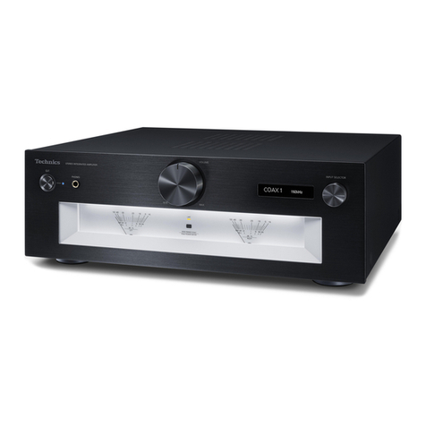
  9. Technics SU-V2X User manual

Technics SU-V2X User manual

Other Technics Amplifier manuals

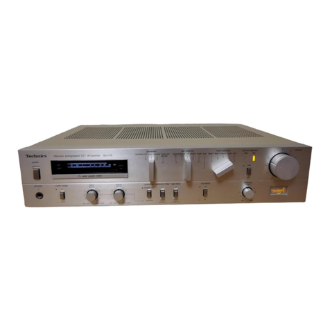
Technics SU-X901 - service User manual

Technics

Technics SU-X901 - service User manual

Technics SE-CH610 User manual

Technics

Technics SE-CH610 User manual

Technics SE-CH530 User manual

Technics

Technics SE-CH530 User manual

Technics SE-9060 (XM) User manual

Technics

Technics SE-9060 (XM) User manual

Technics SE-CH505A User manual

Technics

Technics SE-CH505A User manual

Technics SU-8055 X User manual

Technics

Technics SU-8055 X User manual

Technics SU-X320 User manual

Technics

Technics SU-X320 User manual

Technics SE-A800S - service User manual

Technics

Technics SE-A800S - service User manual

Technics SU-V5 User manual

Technics

Technics SU-V5 User manual

Technics SA-CH750 User manual

Technics

Technics SA-CH750 User manual

Technics SU-R1000E-S User manual

Technics

Technics SU-R1000E-S User manual

Technics SU-VX620 - service User manual

Technics

Technics SU-VX620 - service User manual

Technics SU-C800U User manual

Technics

Technics SU-C800U User manual

Technics SE-HD501 User manual

Technics

Technics SE-HD501 User manual

Technics SU-Z35 User manual

Technics

Technics SU-Z35 User manual

Technics SU-7100 (XE) User manual

Technics

Technics SU-7100 (XE) User manual

Technics SU-G700 User manual

Technics

Technics SU-G700 User manual

Technics SECH-515-A User manual

Technics

Technics SECH-515-A User manual

Technics SU-A900 User manual

Technics

Technics SU-A900 User manual

Technics SU-G50 User manual

Technics

Technics SU-G50 User manual

Technics SU-A600 User manual

Technics

Technics SU-A600 User manual

Technics SU-V650 User manual

Technics

Technics SU-V650 User manual

Technics SE-A800S - service User manual

Technics

Technics SE-A800S - service User manual

Technics SU-A800 User manual

Technics

Technics SU-A800 User manual

Popular Amplifier manuals by other brands

Magnat Audio EDITION FOUR Owner's manual/warranty document

Magnat Audio

Magnat Audio EDITION FOUR Owner's manual/warranty document

Inter-m PA-2000A Operation manual

Inter-m

Inter-m PA-2000A Operation manual

Yamaha TX6n owner's manual

Yamaha

Yamaha TX6n owner's manual

Peavey TNT 150 user guide

Peavey

Peavey TNT 150 user guide

Bosch LBB 1903/10 Installation and user instructions

Bosch

Bosch LBB 1903/10 Installation and user instructions

Avocent Emerge DA1200D Installer/user guide

Avocent

Avocent Emerge DA1200D Installer/user guide

Redgum RGi35 operating instructions

Redgum

Redgum RGi35 operating instructions

Cambridge Audio AXA25 user manual

Cambridge Audio

Cambridge Audio AXA25 user manual

Alpine MRP-M200 owner's manual

Alpine

Alpine MRP-M200 owner's manual

Technical Pro H1502UrBT user manual

Technical Pro

Technical Pro H1502UrBT user manual

FMS EMGZ307 operating manual

FMS

FMS EMGZ307 operating manual

Racal Instruments 5601 user manual

Racal Instruments

Racal Instruments 5601 user manual

Valcom V-1094A Technical specifications

Valcom

Valcom V-1094A Technical specifications

Cambridge Audio 851D user manual

Cambridge Audio

Cambridge Audio 851D user manual

QSC 3800 Specifications

QSC

QSC 3800 Specifications

NAD C300 owner's manual

NAD

NAD C300 owner's manual

Rotel RMB-1077 owner's manual

Rotel

Rotel RMB-1077 owner's manual

Peavey Monitor 300 Series operating guide

Peavey

Peavey Monitor 300 Series operating guide

manuals.online logo
manuals.online logoBrands
  • About & Mission
  • Contact us
  • Privacy Policy
  • Terms and Conditions

Copyright 2025 Manuals.Online. All Rights Reserved.

ORDER
NO.
HAD84072860C8
Service
Manual
Amplifier
Stereo
Integrated
Amplifier
S
U
-
Vx
Computer
Drive
New
Class
A
Color
(K)
--+-
Black
Type
(S)
---+
Silver
Type
Color
Area
(K)(S)
|
[E)-----
Switzerland
and
Scandinavia
(S)
|
[EF]
----
France
(K)(S)
|
[Ei]
----
Italy
(K)(S)
|
[EK]----
United
Kingdom
(K)(S)
|[EH].---
Holland
(K)(S)
|
[EGA]---
F.R.
Germany
(K)(S)
|
[EB]
----
Belgium
(K)(S)
|[XA]
+--+
Asia,
Latin
America,
Africa,
Middle
Near
East
and
Oceania
(K){S)
|[XL]
---
Australia
|
SPECIFICATIONS
(DIN
45
500)
Frequency
response
@
AMPLIFIER
SECTION
PHONO
RIAA
standard
curve
+0.8
dB
(30
Hz~15
kHz)
1
kHz
continuous
power
output
TUNER,
CD,
VIDEO/AUX,
both
channels
driven
2x50
W
(4Q)
TAPE
1/DA
TAPE,
TAPE
2 5
see
5
bee
ete
250
W
(8Q)
+0,
—0.2
dB
(20
Hz~
z)
20
Hz~20
kHz
continuous
power
output
eae
ee
ad
a
dB
both
channels
driven
2x45
W
(4Q)
ubsonic
filter
Z,-
oct.
2x45
W
(8Q)
Loudness
control
(volume
at
—30
dB)
50Hz,
+9dB
Total
harmonic
distortion
pee
ana
rated
power
at
20
Hz~20
kHz
0.03%
(40)
REC
OUT
150
mV
0.005%
(8)
Channel
balance,
VIDEO/AUX
250
Hz~6,300
Hz
+1dB
rated
power
at
1
kHz
0.007%
(4Q)
Channel
separation,
VIDEO/AUX
1
kHz
60 dB
0.003%
(8)
Headphones
output
level
and
impedance
450
mV/3300
half
power
at
20
Hz~20
kHz
0.003%
(8Q)
Load
impedance
half
power
at
1
kHz
0.001%
(8Q)
MAIN
or
REMOTE
AN~
160
Intermodulation
distortion
MAIN
and
REMOTE
80~160
rated
power
at
250
Hz:
8
kHz=4:1,
8Q
0.03%
rated
power
at
60
Hz:
7
kHz=4:1,
SMPTE,
8
0.005%
Power
bandwidth
m@
GENERAL
both
channels
driven,
—3
dB
5
Hz~40
kHz
(40,
0.03%)
:
BaEW
5
Hz~50
kHz
(82,
0.02%)
Sibel
seer
;
ower
supply
Peatkaiey
pores
ae
For
United
Kingdom
AC
50H
2/60
Hz,
a
eatin
Bree
ee!
110
V/120
V/229
V/240V
I
ra
:
peace
Pee
sana
2.5
mV/47
kQ
For
continental
Europe
AC
50
H2/60
Hz,
220V
TUNER,
CD,
VIDEO/AUX
150
mV/22
kQ
For
others
ste
eu
en
ee
Be
1
V/22
kQ
SaonG
Lane
Ligue:
baer
eee
Dimensions
(WxHxD)
430
x97:<
290
mm
maximum
input
voltage
(1
kHz,
RMS)
160
mV
(16-18/16"x3-27/32"x)
4-7/16")
ly
Weight
6.3
kg
rated
power
(40)
(13.9
Ib)
PHONO
76
dB
(IHF,
A:
83
dB)
Note:
fe
TUNER,
CD,
VIDEO/AUX,
.
oe
eae
<n
TAPE
1/DA
TAPE,
TAPE
2
91
dB
(IHF,
A:
102
dB)
Total
harmonic
distortion
is
measured
by
the
digital
spectrum
T
analyzer
(H.P.
3045
system).
one
controls
BASS
50
Hz,
+10
dB~—10
dB
Specifications
are
subject
to
change
without
notice
fo;
further
TREBLE
20
kHz,
+10
dB~—10
dB
improvent.
:
;
e
h
he
Matsushita
Electric
Trading
Co.,
Ltd.
Cc
hn1icS
P.O.
Box
288,
Central
Osaka
Japan
@
CONTENTS
Page
PROTECTION
CIRCUITRY
.....-.
2.00.2
0s
eevee
nneee
2
BEFORE
REPAIR
AND
ADJUSTMENT
..........22028.
2
LOCATION
OF
CONTROLS...
....
2.5.0
ee
eee
eee
2,3
DISASSEMBLY
INSTRUCTIONS
.............2..002.
4~6
TERMINAL
GUIDE
OF
TRANSISTORS,
DIODES
AND
IC’S....
6
FUNCTION
OF
TERMINAL
1C601
(IcQ
control)...
ee
7
1C401
(Analog
function
control)...
.
2...
2.
ee
ee
8
Mi
PROTECTION
CIRCUITRY
The
protection
circuitry
may
have
operated
if
either
of
the
following
conditions
is
noticed:
@
No
sound
is
heard
when
the
power
is
turned
on.
@
Sound
stops
during
a
performance.
The
function
of
this
circuitry
is
to
prevent
circuitry
damage
if,
for
example,
the
positive
and
negative
speaker
connection
wires
are
‘‘shorted’’,
or
if
speaker
systems
with
an
impedance
less
than
the
indicated
rated
im-
pedance
of
this
unit
is
used.
Page
CIRCUIT
BOARDS
AND
WIRING
CONNECTION
DIAGRAM).
|.c3-605
Seetcce
5a
Saree
ee
eek
ae
a
9,10
PRINTED
CIRCUIT
BOARDS
................00-
11~13
BLOCK
DIAGRAM
....
2...
2.2...
ee
ee te
ee
14,15
SCHEMATIC
DIAGRAM
...
1...
.
.
eee
ee
ee
16~20
RESISTORS
&
CAPACITORS
.............00
00205
ae
21
REPLACEMENT
PARTS
LIST............
02000
eu
uue
22
EXPLODED
VIEW
iota
ce
eae
ek
Goa
ae
Oe
ae
23,
24
If
this
occurs,
follow
the
procedure
outlines
below:
1.
Turn
off
the
power.
2.
Determine
the
cause
of
the
problem
and
correct
it.
3.
Turn
on
the
power
once
again.
Note
When
the
protection
circuitry
functions,
the
unit
will
not
operate
unless
the
power
is
first
turned
off
and
then
on
again.
M@
BEFORE
REPAIR
AND
ADJUSTMENT
1.
Disconnect
AC
power,
Discharge
both
Power
Supply
Capacitors
C701
and
C702
(8200uF)
through
a
102,
5W
resistor
to
ground.
DO
NOT
SHORT-CIRCUIT
DIRECTLY
(with
a
screwdriver
blade,
for
instance),
as
this
may
distroy
solid
state
devices.
2.
After
repairs
are
completed,
restore
power
gradually
using
a
variac,
to
avoid
overcurrent.
Current
consumption
at
50/60Hz
in
NO
SIGNAL
mode
should
be
shown
below
with
respect
to
supply
voltage
110V/
120V/220V/240V.
Power
supply
voltage
AC110V
AC120V AC220V
AC240V
Hi
LOCATION
OF
CONTROLS
Operation
indicator
Computer
drive
automatic
indicator
Power
switch
igirtbons
(bass)
Tone
controls]
|
(treble)
Tone
switch
(
HL
defeat,
=
on)
Subsonic
fitter
switch
(
HL
off,
=
on}
170
~360mA
90
~
200mA
80
~180mA
Balance
control
Audio
muting
switch
(
off
—»—20dB)
Loudness
switch
(
9
off,
=
on)
Volume
control
é
Recording
output
4}.
signal
indicator
{et
Input
signal
:
indicator
Selectors
(tape
1/DA
tape}
Recording
mode
switch
Recording
mode
indicator
ESPANOL
ESPANOL
@
ESPECIFICACIONES
(DIN
45
500)
m@
SECCION
AMPLIFICADOR
Potencia
continua
de
1
kHz
en
ambos
canaies
2x50
W
(4Q)
2x50
W
(8Q)
Potencia
continua
de
20
Hz~20
kHz
en
ambos
canales
2x45
W
(4Q)
2x45
W
(8Q)
Distorsio6n
armonica
total
potencia
de
régimen
a
20
Hz~
20
kHz
0,03%
(49)
0,005%
(8Q)
0,007%
(4Q)
0,003%
(8Q)
0,003%
(8Q)
0,001%
(8Q)
potencia
de
régimen
a1
kHz
mitad
de
potecia
a
20
Hz~20
kHz
mitad
de
potencia
a
1
kHz
Distorsion
por
intermodulacion
potencia
de
régimen
a
250
Hz:
8
kHz=4:1,
8Q
0,03%
potencia
de
régimen
a
60
Hz:
7
kHz=4:1,
SMPTE,
8Q
0,005%
Ancho
de
banda
de
potencia
en
ambos
canales,
—3
dB
5
Hz~40
kHz
(4Q,
0,03%)
5
Hz~50
kHz
(8,
0,02%
)
0,9
mV
30
(4Q),
60
(8Q)
Zumbido
residual
y
ruido
Factor
de
amortiguamiento
Sensibilldad
e
impedancia
de
entrada
TOCADISC.
(PHONO)
2,5
mV/47
kQ
SINTON.,
DISCO
COMPACTOR,
VIDEO/AUX.
(TUNER,
CD,
VIDEO/AUX)
150
mV/22
kQ
GRAB.
1/DIGITAL,
GRAB.
2.
(TAPE
1/DA
TAPE,
TAPE
2)
150
mV/22
kQ
Voltaje
maximo
de
entrada
de
PHONO
(1
kHz,
RMS)
Relacion
de
sefal
a
ruido
potencia
de
régimen
(40)
TOCADIS.
(PHONO)
76
dB
(IHF,
A:
83
dB)
SINTON.,
DISCO
COMPACTO,
VIDEO/AUX,
GRAB.
1/DIGITAL,
GRAB.
2
(TUNER,
CD,
VIDEO/AUX,
TAPE
1/DA
TAPE,
TAPE
2)
160
mV
91
dB
(IHF,
A:
102
dB)
Respuesta
de
frecuencia
TOCADISC.
(PHONO)
curva
RIAA
estandar
+0,8
dB
(30
Hz~15
kHz)
SINTON.,
DISCO
COMPACTO,
VIDEO/AUX,
GRAB.
1/DIGITAL,
GRAB.
2
(TUNER,
CD,
VIDEO/AUX,
TAPE
1/DA
TAPE,
TAPE2)
5
Hz~120
kHz
(—3
cB),
+0,
—0,2
dB
(20
Hz~20
kHz)
Controles
de
tono
BAJOS
(BASS)
50
Hz,
+10
dB~-10dB
AGUDOS
(TREBLE)
20
kHz,
+10
dB~—10dB
Silenciamiento
-—20dB
Filtro
subsénico
30
Hz,
~6
dB/oct.
Control
de
sonoridad
(volumen
a
—30
dB)
50
Hz,
+9
dB
Voltaje
de
salida
SAL.
GRAB.
(REC
OUT)
150
mV
Equilibrio
de
canales,
VIDEO/AUX
250
Hz~6300
Hz
+1dB
Separacion
de
canales,
VIDEO/AUX
1
kHz
60dB
impedancia
y
nivel
de
salida
de
los
auriculares
450
mV/330Q
Impedancia
de
carga
MAIN
o
REMOTE
40~1602
MAIN
y
REMOTE
8N~16Q
m
GENERAL
Consumo
de
energia
295
W
Alimentacion
de
energia
Para
Europa
continental
CA
50/60
Hz,
220
V
Para
otros
paises
CA
50
H2/60
Hz,
110
V/120
V/220
V/240
V
Dimensiones
(An.
XAl.
x
Prof.)
430x97x290
mm
Peso
6,3
kg
Nota:
La
distorsién
armonica
total
se
mide
con
el
analizador
de
espec-
tro
digital
(sistema
H.P.
3045).
Estas
especificaciones
estan
sujetas
a
cualquier
cambio
sin
Previo
eviso.
@
CIRCUITS
TO
BE
CHANGED
AND
THE
AREAS
e
Power
supply
circuits
For
[EK]
area
([EK]
is
available
in
United
Kingdom)
S13
A!
POWER)
AC
1110/1207
220/240V
(50/60Hz)
For
[XL]
area
((XL]
is
available
in
Australia)
AC
HO/120/7
220/240V
(50/60Hz)
|
Ac
10/1207
220/240V
(50/60H2z}
AUNSWITCHED
fh
onl
cy
Printed
in
Japan
af
840707100
®
YK/IM
Stereo
Integrated
Amplifier
ORDER
NO.
HAD84072860C8—A
SU-V2X
@
This
booklet
includes
the
specifications
of
Model
SU-V2X
(Order
No.
HAD84072860C8)
written
in
German,
French
and
Spanish.
®@
File
this
booklet
together
with
the
service
manual
of
Model
SU-V2X.
@
Dieses
Biichlein
umfaRt
die
technischen
Daten
von
Modell
Deutsch,
Franzdésisch
und
Spanisch.
SU-V2X_
(Bestell-Nr.
HAD84072860C8)
in
den
Sprachen
@
Bewahren
Sie
dieses
Buchlein
zusammen
mit
dem
Service-Handbuch
von
Modell
SU-V2X
auf.
©
Cette
brochure
comprend
les
spécifications
du
Modéle
SU-V2X
(N°
d’Ordre:
HAD84072860C8)
écrites
en
frangais,
en
allemand
et
en
espagnol.
@
Classer
cette
brochure
en
méme
temps
qu‘avec
le
manuel
de
service
du
Modéle
SU-V2X.
@
Este
librito
incluye
las
especificaciones
de
Modelo
SU-V2X
(Pedido
N°,
HAD84072860C8)
escritas
en
aleman,
francés
y
espanol.
®
Guardar
este
librito
juntamente
con
el
manual
de
servicio
de
Modelo
SU-V2X.
DEUTSCH
Mi
TECHNISCHE
DATEN
(DIN
45
500)
@
VERSTARKERTEIL
Dauerton-Ausgangsleistung
bei
1
kHz
beide
Kandle
ausgesteuert
2x50
W
(40)
2x50
W
(8Q)
Dauerton-Ausgangsleistung
bei
20
Hz~20
kHz
beide
Kandale
ausgesteuert
2x45
W
(4Q)
2x45
W
(8Q)
Gesamtklirrfaktor
Nennleistung
bei
20
Hz~
20
kHz
0,03%
(4)
0,005%
(8Q)
Nennleistung
bei
1
kHz
0,007%
(4Q)
0,003%
(89)
halbe
Nennleistung
bei
20
Hz~
20
kHz
0,003%
(8)
halbe
Nennleistung
bei
1
kHz
0,001
%
(8Q)
Intermodulationsfaktor
Nennleistung
bei
250
Hz:
8
kHz=4:1,
8
Q
0,03%
Nennleistung
bei
60
Hz:
7
kHz=4:1,
nach
SMPTE,
80
0,005%
Leistungsbandbreite
beide
Kanale
ausgesteuert
bei
—3
dB
5
Hz~40
kHz
(4Q,
0,03%)
5
Hz~50
kHz
(8,
0,02%)
Restbrumm
und
Gerausch
0,9
mV
Dampfungstaktor
30
(49),
60
(8Q)
Eingangsempfindlichkeit
und
-impedanz
Phono
2,5
mV/47
kQ
TUNER,
CD,
VIDEO/AUX,
TAPE
1/DA
TAPE,
TAPE
2
150
mV/22
kQ
Maximale
T
A-Eingangsspannung
(1
kHz,
eff.)
160
mV
Gerauschspannungsabstand
Nennleistung
(40)
Phono
76
dB
(nach
IHF,
A:
83
dB)
TUNER,
CD,
VIDEO/AUX,
TAPE
1/DA
TAPE,
TAPE
2
91
dB
(nach
IHF,
A:
102
dB)
Frequenzgang
Phono
RIAA-Stand
ardkurve
+0.8
dB
(30
Hz~15
kHz)
TUNER,
CD,
VIDEO/AUX,
TAPE
1/DA
TAPE,
TAPE
2 5
Hz~120
kHz
(—3
dB)
+0,
—0,2
dB
(20
Hz
~20
kHz)
Klangregler
BaBregler
(BASS)
50
Hz,
+10
dB
~-10dB
Héhenregler
(TREBLE)
20
kHz,
+10dB~—10dB
Tondampfung
—20dB
Tiefenfilter
30
Hz,
~
6
dB/Okt.
Lautstarkekorrektur
(Loudness)
(bei
—30
dB
Ausgangsleistung)
50Hiz,
+9
dB
Ausgangsspannung
Aufnahmeausgang
(REC
OUT)
150
mV
Kanalabweichung
(VIDEO/AUX,
250
Hz~6
300
Hz)
+1dB
Ubersprechdampfung
(VIDEO/AUX,
1
kHz)
60
dB
Kopfhérerpegel
und
-impedanz
456
mV/3300
Lautsprecherimpedanz
MAIN
oder
REMOTE
40~160
MAIN
und
REMOTE
80~160
@
ALLGEMEINE
DATEN
Leistungsaufnahme
295W
Netzspannung
Fir
Kontinentaleuropa
Wechselstrom
50
Hz/60Fiz,
220
V
Fur
andere
Lander
Wechselstrom
50t-42/60
Hz,
110
V/120
V/21O
V/240
V
Abmessungen
(BXHxT)
430
x
9)>«
290
mm
Gewicht
6,3
kg
Bemerkung:
Der
Gesamtklirrfaktor
wurde
mit
einem
digitalen
Rausd~spektro-
meter
(Anlage
H.P.
3045)
gemessen.
Spezifikationen
kénnen
infolge
von
Verbesserungen
g
me
Ankiindigung
geandert
werden.
x
iS)
7)
|
od
=)
Ww
a
FRANCAIS
FRANCAIS
Mi
CARACTERISTIQUES
(DIN
45
500)
m@
SECTION
AMPLIFICATEUR
Puissance
de
sortie
continue
a
1
kHz
les
deux
canaux
en
circuit
2x50
W
(4Q)
2x50
W
(8Q)
Puissance
de
sortie
continue
de
20
Hz~20
kHz
les
deux
canaux
en
circuit
2x45
W
(40)
2x45
W
(8Q)
Distorsion
harmonique
totale
a
puissance
nominale
(20
Hz~20
kHz)
0,03%
(4Q)
0,005%
(8Q)
0,007%
(4Q)
0,003%
(8Q)
0,003%
(8)
0,001%
(8Q)
a
puissance
nominale
(1
kHz)
a
demi-puissance
(20
Hz~20
kHz)
a
demi-puissance
(1
kHz)
Distorsion
d’intermodulation
a
puissance
nominale
a
250
Hz:
8
kHz=4:1,
8Q
0,03%
a
puissance
nominale
a
60
Hz:
7
kHz=4:1,
SMPTE,
80
0,005%
Réponse
de
fréquences
les
deux
canaux
en
circuit,
—3
dB
5
Hz~40
kHz
(4Q,
0,03%)
5
Hz~50
kHz
(8,
0,02%)
0,9
mV
30
(49),
60
(8)
Bruit
et
ronflement
résiduels
Coefficient
d’amortissement
Sensibilité
et
impédance
d’entrée
PHONO
2,5
mV/47
kQ
SYNTONISATEUR,
DISQUE
COMPACT,
VIDEO/AUX,
BANDE
1/DIGITALE,
BANDE
2
(TUNER,
CD,
VIDEO/AUX,
TAPE
1/DA
TAPE,
TAPE
2)
PHONO
(tension
d’entrée
maximum,
1
kHz
RMS)
Signal/Bruit
a
puissance
nominale
(4Q)
PHONO
76
dB
(IHF,
A:83
dB)
SYNTONISATEUR,
DISQUE
COMPACTO,
VIDEO/AUX,
BANDE
1/DIGITALE,
BANDE
2
(TUNER,
CD,
VIDEO/AUX,
TAPE
1/DA
TAPE,
TAPE
2)
91
dB
(IHF,
A:
102
dB)
150
mV/22
k<Q
160
mV
Réponse
de
fréquence
PHONO
Courbe
nominale
RIAA
+0,8
dB
(30
Hz~
15
kHz)
SYNTONISATEUR,
DISQUE
COMPACTO,
VIDEO/AUX,
BANDE
1/DIGITALE,
BANDE
2
(TUNER,
CD,
VIDEO/AUX,
TAPE
1/DA
TAPE,
TAPE
2)
5
Hz~120
kHz
(—3
dB)
+0,
—0,2
dB
(20
Hz~20
kHz)
Reéglage
de
la
tonalité
BASSES
(BASS)
AIGUS
(TREBLE)
50
Hz,
+10
dB~-—10dB
20
kHz,
+10
dB~-10dB
Réglage
silencieux
—20
dB
Filtre
subsonique
30
Hz,
—6
dB/oct.
Compensateur
physiologique
(volume
a
—30
dB)
50
Hz,
+9
dB
Tension
de
sortie
SORTIE
ENREGISTREMENT
(REC
OUT)
150
mV
Equilibrage
des
canaux,
VIDEO/AUX
250
Hz~6300
Hz
+1dB
Séparation
des
canaux,
VIDEO/AUX
1
kHz
60
dB
Niveau
de
sortie
des
casques
et
impédance
450
mV/3300
impédance
de
charge
PRINCIPALE
ou
AUXILIAIRE
(MAIN
or
REMOTE)
40~160
PRINCIPALE
et
AUXILIAIRE
(MAIN
and
REMOTE)
80~160
@
DIVERS
Consommation
295
W
Alimentation
Pour
|l’Europe
CA
50
H2/60
Hz,
220
V
Autres
CA
50
Hz/60
Hz,
110
V/120 V/220
V/240
V
Dimensions
(LXHxPr)
430x97x290
mm
Poids
6,3
kg
Remarques:
1.
On
mesure
la
distorsion
harmonique
totale
au
moyen
d’un
analyseur
de
spectre
digital
(Systeme
H.P.
3045).
2.
La
Société
NATIONAL-PANASONIC-FRANCE,
importateur
du
matériel
MATSUSHITA-ELECTRIC
déclare
que
cet
appa-
reil
est
conforme
aux
prescriptions
de
la
directive
76/889
/C.E.E.
(arrété
14
Janvier
1980).
Sujet
4
changement
sans
prearis.
(Switched)
AC
outlets
layback
Tape
IDA
tape
'P
ayback)
(Unswitched)
({XA]
area
only)
(Rec
out)
Main
speaker
{R)
Ground
(R)
(L)
(expect
for
[XL]
area)
Voltage
selector
(110V
~—»1
20V-——»220V-~——»240V)
(For
[EK},
[XL],
[XA]
areas
only)
Speaker
impedance
selector
(Rec
out)
(
gg
Main
or
remote
8~162.
_
Main
or
remote
4
~62.
)
Tape
2
Main
and
remote
16022
,
~—
Main
and
remote
8].
(Playback)
Tuner
input
CD
input
Remote
speaker
Video/aux
input
e
Speaker
impedance
selector
Set
to
the
position
corresponding
to
the
impedance
of
the
speaker
systems
being
Note
that,
if
2
pairs
of
speaker
systems
are
used
at
the
same
used.
time,
determine
the
composite
impedance
as
described
below.
If
this
setting
is
not
correctly
made,
the
result
may
be
a
deterioration
of
performance.
*
If
either
the
main
or
the
remote
speaker
systems
are
used:
Bee
“Ee
4~60,(8—~=):
~
a
eeobaan
Fat
cneaks
systems
.
=
re
aa
of
a=68.
ns
connected
to
“MAIN”
terminals
Re=impedance
of
speaker
systems
For
speaker
impedance
of
8~160.
connected
to
‘‘REMOTE”
terminals
*
If
both
main
and
remote
speaker
systems
are
used:
80.
(a~-):
For
speaker
impedance
of
80
or
more
and
less
than
162.
160.
(.~8):
Note:
For
speaker
impedance
of
160.
Be
sure
to
make
this
setting
before
switching
the
power
‘‘on”.
®@
The
power
supply
for
this
unit
varies
depending
upon
the
areas.
Also,
the
parts
used
for
power
supply
are
different.
So,
refer
to
the
circuit
diagram
(Separate
service
manual:
Order
No.
HAD84072860C8—A)
and
the
replacement
parts
list.
*
[XA],
[EK]
and
[XL]
areas
are
provided
with
voltage
selector.
*
220V
(50/60Hz)
for
Continental
Europe.
(Except
for
United
Kingdom)
*
110V/120V/220V/240V
(50/60Hz)
for
[XA],
[EK]
and
[XL]
areas.
*
Phono
input
capacitance
is
about
150pF.
Mi
DISASSEMBLY
INSTRUCTIONS
fee
How
to
remove
the
cabinet
1
1.
Remove
the
4
screws
(@~
@)
How
to
remove
the
front
panel
1,
Remove
the
4
screws.
(
@~
@)
2.
Remove
the
volume
knob.
3.
Remove
the
1
nut.
(@)
4,
Pull
out
the
4
connectors.
(J7
~
J9,
J11)
Procedure
1
3
—
Rear
panel
ae
How
to
remove
the
input
selector
P.C.B.
Procedure
|
1
Remove
the
3
screws.
(@~@)
3.
Remove
the
input
selector
P.C.B.
1
+3
+4
~
2.
Push
the
11
tabs.
(
(4)
®
)
Front
panel
Front
panel
Input
selector
P.C.B.
How
to
remove
the
balance/tone
control
P.C.B.
Procedure
1.
Remove
the
3
knobs.
5.
Remove
the
balance/tone
control
P.C.B.
1
+3
+5]
2,
Remove
the
3
nuts.
(Q@~®@)
3.
Remove
the
3
covers.
4.
Remove
the
1
screw.
(
@)
Balance/tone
control
P.C.B.
.
*)
Balance/tone
>
nobs
Cover
control
P.C.B.
,
Front
chassis
oY
No.
|
How
to
remove
the
power
IC
:
argu:
1,
Unsolder
the
power
IC.
za
2.
Remove
the
2
screws
(@,
@)
Rear
panel
Power
IC
When
mounting
the
power
amplifier
IC,
apply
silicon
compound
(SZZOL15)
to
the
rear
of
the
power
amplifier
IC.
Screwdriver
pee
No.
How
to
remove
the
sub
panel
Procedure
1.
Push
the
4
tabs
of
the
sub
panel.
1
+3
+4
+7
2.
Remove
the
sub
panel
in
the
direction
of
the
arrow
@®
;
Front
panel
Screwdriver
2802631,
2801123
[MN4069UB
_|
14pin|
‘
2SA992,
2SC3112
M53249P
|
YP
3
/
.
Ga
Drain
‘s
.
Gate
Source
3.
Source
:
~™=16
MA165,
MA167
Front
panel
SVINJM20430D
AN6553F