manuals.online logo
Brands
  1. Home
  2. •
  3. Brands
  4. •
  5. Technics
  6. •
  7. Amplifier
  8. •
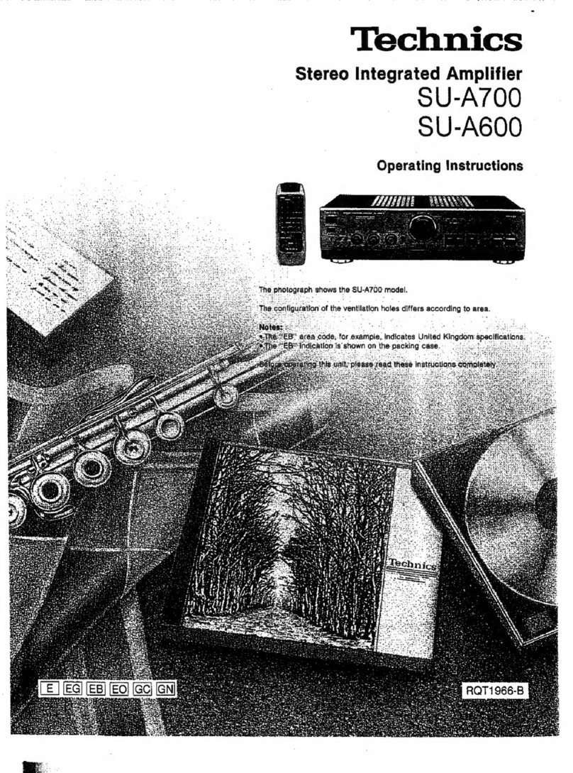
  9. Technics SU-V36 User manual

Technics SU-V36 User manual

Other Technics Amplifier manuals

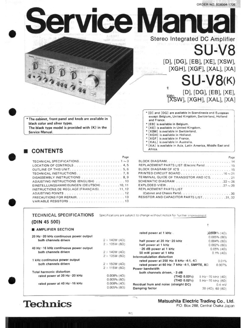
Technics SU-V8 User manual

Technics

Technics SU-V8 User manual

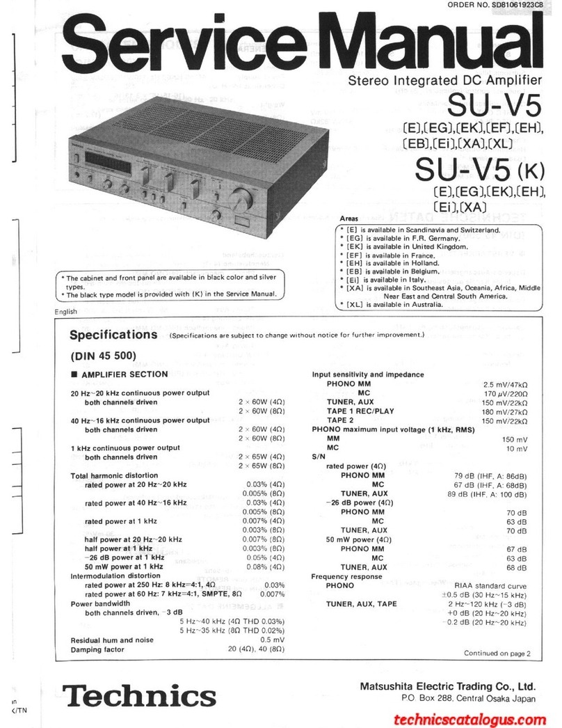
Technics SU-X901 - service User manual

Technics

Technics SU-X901 - service User manual

Technics SU-7100 (XE) User manual

Technics

Technics SU-7100 (XE) User manual

Technics SU-7300 - service User manual

Technics

Technics SU-7300 - service User manual

Technics SE-HD350 Building instructions

Technics

Technics SE-HD350 Building instructions

Technics SU-V6 User manual

Technics

Technics SU-V6 User manual

Technics SU-V460 User manual

Technics

Technics SU-V460 User manual

Technics SU-A600 User manual

Technics

Technics SU-A600 User manual

Technics SE-A800S - service Instruction manual

Technics

Technics SE-A800S - service Instruction manual

Technics SU-X520D User manual

Technics

Technics SU-X520D User manual

Technics SU-7700 - SCHEMATICS User manual

Technics

Technics SU-7700 - SCHEMATICS User manual

Technics SU-VX620 - service User manual

Technics

Technics SU-VX620 - service User manual

Technics SU-A900 User manual

Technics

Technics SU-A900 User manual

Technics SU-VX620 - service User manual

Technics

Technics SU-VX620 - service User manual

Technics SA-EH780E User manual

Technics

Technics SA-EH780E User manual

Technics SU-X120 User manual

Technics

Technics SU-X120 User manual

Technics SE-A3K - service User manual

Technics

Technics SE-A3K - service User manual

Technics SA-EH550 User manual

Technics

Technics SA-EH550 User manual

Technics SU-V500M2 User manual

Technics

Technics SU-V500M2 User manual

Technics SE-A1000 User manual

Technics

Technics SE-A1000 User manual

Technics su-s3000 User manual

Technics

Technics su-s3000 User manual

Technics SU-A900 User manual

Technics

Technics SU-A900 User manual

Technics SU-V620 - SERVICE User manual

Technics

Technics SU-V620 - SERVICE User manual

Technics SU-R1000E-S User manual

Technics

Technics SU-R1000E-S User manual

Popular Amplifier manuals by other brands

Magnat Audio EDITION FOUR Owner's manual/warranty document

Magnat Audio

Magnat Audio EDITION FOUR Owner's manual/warranty document

Inter-m PA-2000A Operation manual

Inter-m

Inter-m PA-2000A Operation manual

Yamaha TX6n owner's manual

Yamaha

Yamaha TX6n owner's manual

Peavey TNT 150 user guide

Peavey

Peavey TNT 150 user guide

Bosch LBB 1903/10 Installation and user instructions

Bosch

Bosch LBB 1903/10 Installation and user instructions

Avocent Emerge DA1200D Installer/user guide

Avocent

Avocent Emerge DA1200D Installer/user guide

Redgum RGi35 operating instructions

Redgum

Redgum RGi35 operating instructions

Cambridge Audio AXA25 user manual

Cambridge Audio

Cambridge Audio AXA25 user manual

Alpine MRP-M200 owner's manual

Alpine

Alpine MRP-M200 owner's manual

Technical Pro H1502UrBT user manual

Technical Pro

Technical Pro H1502UrBT user manual

FMS EMGZ307 operating manual

FMS

FMS EMGZ307 operating manual

Racal Instruments 5601 user manual

Racal Instruments

Racal Instruments 5601 user manual

Valcom V-1094A Technical specifications

Valcom

Valcom V-1094A Technical specifications

Cambridge Audio 851D user manual

Cambridge Audio

Cambridge Audio 851D user manual

QSC 3800 Specifications

QSC

QSC 3800 Specifications

NAD C300 owner's manual

NAD

NAD C300 owner's manual

Rotel RMB-1077 owner's manual

Rotel

Rotel RMB-1077 owner's manual

Peavey Monitor 300 Series operating guide

Peavey

Peavey Monitor 300 Series operating guide

manuals.online logo
manuals.online logoBrands
  • About & Mission
  • Contact us
  • Privacy Policy
  • Terms and Conditions

Copyright 2025 Manuals.Online. All Rights Reserved.

Technics
Stereo
Integrated
Amplifier
SU-V36
OPERATING
INSTRUCTIONS
Before
operating
this
unit,
please
read
these
instructions
completely.
We
want
to
thank
you
for
selecting
this
product
and
to
welcome
you
to
the
growing
family
of
satisfied
Technics
product
owners
around
the
world.
We
feel
certain:
you
will
get
maximum
enjoyment
from
this
new
addition
to
your
home.
Please
read
these
operating
instructions
carefully,
and
be
sure
to
keep
them
handy
for
convenient
reference.
These
operating
instructions
are
aeP
ieee
to
the
following
components.
wen
eye
When
using
with
components.
descrifed
at
the
left
These
operating
instructions
describe
system
connections
and
basic.
operations.
including.
remote-control.
operations:
(The:
remote-control:
transmitter’
is
included
with
the.
tuner):
For.
detailed
information:
about
each
unit,
refer
to
their.
individual
operating
instructions.
:
~
-RS-T55R
"
SH-8016
SL-P117
SL-BD26U
When
using
with
other
components
Refer:
to:
their
individual
operating
instructions
concerning
connections
and
operations.
Contents
Listening
to
Tapes:
2.
eas:
ihe:
8
¢
Technical
Specifications
.................0.5...
2
-e
e
Suggestions
for
Safety
.000.....0.0ccee.
es
e
Listening
to
Compact
Discs
or
e
Accessories
..:...-.:
pi
mene
a
are
a
nt
3
Other
Sources
....:.
ne
Caen
eek Bit
9
e
Before
Use
............
eee
eee
Seer
dies
ok
3
©
Adjusting
the
Tone
Quality
.......
pan
aieines
10
e
Connections
.2.)2.0...05
50.0055
RE
OE
TS
Sk
e
Recording
2.22
Satna
ae
11
e
Front
Panel
Controls
and
Functions
..........
5
¢
Troubleshooting
Guide..............
Back
cover
e
Standard
Operating
Procedures...............
6
©
Protection
Circuitry
..................
Back
cover
e
Listening
to
Radio
Broadcasts
meade
tes
ateaie
toes
7
@
Maintenance
..........................
Back
cover
®
Listening
to
Phono
Discs......
Sedma
iaal
aie
7
ee
ee
Technical
Specifications
HB
AMPLIFIER
SECTION
Input
sensitivity
Load
impedance
PHONO
0.3
mV
(2.5
mV,
THF
’66)
MAIN
or
REMOTE
8~16
ohms
in
.
TUNER,
CD/AUX,
TAPE
1,
TAPE
2/EQ
MAIN
and
REMOTE
8~16
ohms
-
Rated
minimum
sine
wave
RMS
17
mV
(150
mV,
IHF
°66)
power
output
S/N
(IHF,
A)
20
Hz~20
kHz
both
channels
driven
PHONO
71
dB
(73
dB,
IHF
66)
0.05%
total
harmonic
distortion
TUNER,
CD/AUX,
TAPE
1,
TAPE
2/EQ
100W
per
channel
(8
ohms)
75
dB
(94
dB,
IHF
‘66)°
1
kHz
continuous
power
output
Maximum
input
voltage
both
channels
driven
PHONO
128
mV
(135
mV,
1
kHz)
M@
GENERAL
0.05%
total
harmonic
distortion
Input
impedance
100W
per
channel
(8
ohms)
PHONO
47
kilohms
Power
consumption
470W
Dynamic
headroom
1.1
dB
(8
ohms)
TUNER,
CD/AUX,
TAPE
1,
TAPE
2/EQ
Power
supply
Total
harmonic
distortion
20
kilohms
AC
50
Hz/60
Hz,
110V,
127V,
220V,
240V
half
power
at
1
kHz
0.03%
(8
ohms)
SMPTE
intermodulation
distortion
0.05%
(8
ohms)
Frequency
response
PHONO
RIAA
standard
curve
+0.8
dB
TUNER,
CD/AUX,
TAPE
1,
TAPE
2/EQ
10
Hz~80
kHz,
-3
dB
Tone
controls
BASS
50
Hz,
+10
dB~-10
dB
TREBLE
20
kHz,
+10
dB~~10
dB
SUPER
BASS
80
Hz,
+6
dB
Output
voltage
TAPE
1,
2
REC
OUT
150
mV
Low
frequency
damping
factor
50
(8
ohms)
pany
oe
Dimensions
(WXHXD)
430:
119
X
240
mm
(16-15/16"
X:4-11/16"
X
9-7/16")
Weight
7.0
kg
(15.4
lb.)
Note:
Total
harmonic
distortion
is
measured
by
the
digital
spectrum
analyzer
(H.P.
3045
system).
is
eels
for
—
E.Usea
standard
electrical:
AC.
wail
outlet
1.
Use
from
an‘
AC
power
source
of
high
voltage,
such.
as
sfor
air
“conditioners,
is
very.
dangerous.
~
Be
extremely
careful
not
to
make
a
connection
to
he
eS
trical
outlet
for
a
large
air
conditioner
or
central-heating
unit
which
uses
high
voltage,
because
there
is
the
possibility
of
fire.
2.
ADC
power
source
cannot
be
used.
;
Be
sure
to
check
the
power
source
carefully,
sapere
ona
ship
or
other
place
where
DC
is
used.
H
Connection
and
removal
of
the
power
pou
plug
1.
Wet
hands
are
dangerous.
A
dangerous
electric
shock
may
result
if
the
plug
is
touched
“by:
wet
hands.
:
2.
Don’t
pull
the
power
cord.
Always
grasp
the
plug;
never
pull
the
cord
itself.
@
AC
outlet
on
rear
panel
.
Any
equipment
connected
here
should
have
specified
power
consumption
or
less.
This
outlet
is
exclusively
for
the
connection
of
other
audio
equipment,
such
as
a
tape
deck.
Be
sure
the
power
con-
sumption
does
not
exceed
the
wattage
specified
near
the
AC
outlet.
_
2.
Never
connect
other
electrical
appliances,
such
as
an
iron
or
.
toaster.
If
appliances
with
a
large
power
consumption
are
con-
nected,
an
unexpected
accident
might
occur
as
a
result
of
overheating.
@
Never
attempt
to
repair
or
reconstruct
this
unit
A
serious
electric
shock
might
occur
if
this
unit
is
repaired,
disassembled
or
reconstructed
by
unauthorized
persons,
or
if
the
internal
parts
are
accidently
touched.
®
For
families
with
children
Never
permit
children
to
put
anything,
especially
metal,
inside
™
this
unit.
A
serious
electric
shock
or
malfunction
could
occur
if
articles
such
as
coins,
needles,
screwdrivers,
etc.
are
inserted
through:the
ventilation
holes,
etc.
of
this
unit.
Accessories
@
AC
power
supply
cord
(Refer
to
page
4.)................
1
*
Flat
cable
for
remote-control
(Refer
to
page
4.)..........
1
Before
Use
Be
sure:
to:
disconnect.
the
mains:
cord
before
adjusting
the
voltage.
selector.
..
Use
a
minus
(—)
screwdriver
to
set
rine
voltage
selector
(on
the
rear
panel):to
the
voltage
setting
for
the-area
in
ane)
the
unit
will
be
used.
(If
the
power
supply
in
your
areais
117
Vor
120V,
set
to
the’
127
oop
V"
position.)
Note
that
this
unit
wiil
be
seriously
damaged
if
this
setting
is
not.
:
made
correctly.
_@
Turn
off
after
use
oa
‘If
the
unit
is
left
fora
long
time
with
the
power
on,
this
will‘not
a
only
shortenits
useful
operation
life,
but
may.
also
cause
Olas?
:
unexpected.
trouble.
Bee
Bee
@
If
water
is
spilled
on
the
unit
Be
extremely
careful
if
water
is
spilled
on
the
unit,
becausea
fire
or
serious
electric
shock
might.
occur.
Immediately
disconnect
the
power
cord
plug,
and
consult
with
your
dealer.
ee
@
Place
the
unit
where
it
will
be
well
ventilated,
and
away:
from
direct
sunlight
Place
this
unit
at
least
10
cm
(4”)
away
from
wall
surfaces,
etc.,
and
away
from:
direct
sunlight.
Be
careful
that
curtains
and
similar
materials
do
not
obstruct
the
ventilation
holes.
@
Keep
the
unit
away
from
heaters,
etc.
_
Heat
can
damage
the
external
surfaces
as
well
as
‘internal
cir-
cuits
and
components.
@
Avoid
spray-type
insecticides
:
insecticides
might
cause
cracks
or
“cloudiness”
in
the
cabinet
-and
plastic
parts
of
this
unit.
The
gas
usedi
in
such
sprays
might,
moreover,
be
ignited
suddenly.
@
Never
use
alcohol
or
paint
thinner
These
and
similar
chemicals
should
never
be
used,
because
they
may
damage
the
finish.
Bf
If
trouble
occurs
‘if,
during.
operation,
the
sound
is
iriterPapstedt
or
jndieators
no
longer
illuminate,
or
if
abnormal
odor
or
smoke:
is:
detected,
immediately:
disconnect
the
power
cord
plug,
and
contact
your
dealer
or
an
Authorized
Service
Center.
nee
CAUTION:
:
This
equipment
has
been
tested
and
found
to
comply
with
the
limits
for
a
Class
B
computing
device
in
accordance
with
the
specifications
set
forth
in
Subpart
J
of
Part
15
of
the
FCC
Rules.
If
this
equipment
causes
interference
to
radio
or
television
reception
which
can.be
determined
by
turning
the
equipment
on
and
off,
use
the
equipment'in
another
location
and/or
utilize
-fan
electrical
outlet
different
from
that
used
by
the
receiver.
Co
|
}
|
ect
O
i
S
:
If.
connections
of
the.flat
cable
are
wrong,
the-units
do
not.function
correctly.
Turntable
AC
power
supply
cord
(Included
with
Stereo
connection
cable
;
turntable)
(included
with
turntable)
pes)
AC
power
Stereo
connection
cable
‘")
é
.AC.
power
(included
with
tuner)
supply
cord
su
gheth
pply
cord
(Included
(Included
Flat
cable
for
with
tuner)
with
this
remote-control
[a]
unit)
operation
;
@
This
unit
(included
with
this
(SU-V96)(Ry(L)(RY(L)
Nit)
Household
AC
outlet
Stereo
connec-
tion
cables
This
terminal
can
be
used
if,
in
the
future,
a
turn-
Stereo
connec-
table
with
a
(Included
ean
wire
is
with
tape
tion
cable
i
Included
his
deck)
(Ir
pala
a
with
graphic
Seren
TT
Y
equalizer)
qi
Graphic
equalizer
(R)(L)(R)(L)
oi
Connec-
Stereo
connec-
a
|
AC
Gowercioply
Tecnded
nh
remote
cord
(Included
inclu
a
°
with
tape
deck
compact
disc
control
P
)
©)
House-
player)
(Included
:
with
tape
hold
AC
Tape
deck
(R)
(L)(R)
(L)
deck)
outlet
AC
power
supply
cord
(Included
Connection
cable
with
compact
disc
for
remote-control
payer)
(Included
with
compact
disc
player)
Compact
disc
player
“BRE-OUT/MAIN-IN”
terminals:
of
the
amplifier
Do
not
remove
the
shorting
pins
from
these
terminals
unless
you
plan
to
use
the
SU-V96
as
an
independent
preamplifier
or
main
amplifier.
(No
sound
will
be
heard
if
they
are
removed.)
To
use
it
in
this
way,
consult
the
operating
instructions
for
the
additional
amplifier
or
preamplifier
that
you
plan
to
use.
“SPEAKERS”
terminals
_
™@
Connection
of
speaker
systems
@
Twist
the
core
of
the
Oe
connection
cords.
=a
10
mm
@
Press
the
button,
and
+
(13/32")
insert
the
core
until
it
cose
can
no
longer
be
seen.
Twist
@®
Release
the
button,
and
pull
the
cord
gently
to
be
sure
_~
that
it
is
secure.
Note:
To
prevent
damage
to
circuitry,
never
short-circuit
plus
(+)
and
minus
(—)
speaker
terminals.
:
@
“REMOTE”
terminals
For
connection
to
a
second
pair
of
speakers.
H
Load
impedance:
80
~
160.
.....
AC
outlets:
se
@“UNSWITCHED”
outlets
Power
is
always
available,
regardless
of
the
unit’s
power
switch
setting.
Audio
equipment
rated
up
to
60
W
(total
for
all
outlets)
can
be
connected.
Front
Panel
Controls
and
Functions
Power
switch
(power)
Peak-power
meters
(power
level
meter)
These
meters
indicate
tr,
So
value
of
the
output
lew
speaker
systems.
Tone
controls
(bass/treble)
The
bass
control
is
for
the
low-frequency
sound
range,
and
the
treble
control
is.
for
the
high-frequency
sound
range.
Headphones
jack
(phones)
’
Speaker
selectors
(speakers)
main
(
&>
=):
Sound
canbe
heard
from
the
speaker
systems
connected
to
the
“MAIN”
terminals.
remote
(
=—
=):
Sound
can
be
heard
from
the
speaker
systems
connected
to
the
“REMOTE”
terminals.
Note:
al
.
Super
bass
button/indicator
(SUPER
BASS)
The
low-range
sound
can
be
o
&
oF
: ;
'
SLeg
.
s.
|
reinforced.
when
this
button
is
Seo”
ao.
LPF
Sea
~
Soy
oressed.
fs
SELES
LS
<o
$F
“Ne
indi
i
LETC
O
SY
SUS
LK:
~@
indicator
above
the
button
will
Po?
LEP
PP
Poy
Per
OP
Ve.
3
HF
PD
ate.)
2m
§
wo
HO
vm
Sg
£
FSo
LF
OFS
S:
PV
PG
SOS?
PLY.
WSS
DP
QL
FL
LPP
BS
oe
ot
Pe
ess
FSF
Ly
“YB
MRO
D
Oey
ers
oS
oS’:
a
PS
UML
HR
FO
aw
SISOS
PS
PPP
PSP
SK
OL
OVI
IS
Pe
8O
fe
FF
Seeks
Se
‘-ols
FPS
FS
HAP
VPPF
LLL
¥
S$
Wg
LS
SVL
VL
SL
/
SX
“Ps
S
eS
PPO
VSS
od
vey
PS
x
RY
¥
ese
e
PPG
gh
<
og
=
:
2
Sos
s
re
used
to
raise
s
og
&
Fry
LS
lume
(sound)
level.
>
eS:
8
PL
PFS
S
&
Sy
?
LL
PWS
oe
eee
g
Seen
oe
S
This
unit
se
oO.
ks)
Ay
ro
So
¥.
S
Sgr
Py.
Qe.
I>.
ry.
“N
oe
a8
=
.
eh
pene
i)
ie
so
a
eS
o
Fee
FR
oowarse
|
LPN
:
F
Bi
x
Py
an
oc
¥
g
x
aN
A
Pe
&
'?
@
is
LQ
DX.
OL
LN
TP
Sh
“
*
Pe
wo
We
Ox
oF
g
Pew
WP
Mey.
es
uN
/
?
Poe
ey
Fs
"SSS
x
¥
&
Anitor
Balance
controls
(balance)
r/indicator
These
buttons
are
used
to
adjust
left/right
volume
balance.
(ta
@
2/EQ)
Press
this
selector
so
that
the
tape
monitor
indicator
is
ituminated
when
playing
back
or
monitoring
the
sound
from
a
tape
deck,
or
when
using
a
graphic
equalizer,
etc.
connected
to
the
“TAPE
2/EQ”
terminals.
This
selector
should
be
in
the
out
(indicator
OFF)
position
at
all
other
times.
Input
selectors/indicators
‘(input
selector).
These
selectors
are
used
to
select
the
sound
source
to
be
heard,
such
as
a
disc,
radio
broadcast,
etc.
The
corresponding
input
selector
indicator
illuminates
during
operation
to
indicate
the
selected
sound
source.
When
only
one
system
of
speakers
is
connected,
no
sound
willbe
heard
if
both
selectors
are
pressed.
Standard
Operating
Procedures
Before
listervin«
pto
a
disc,
radio
broadcast,
etc.,
(step
1~3)
1
“main”
(
>
=)
and/or
“remote”
(
a—
=)
Note:
When
only
one
system
of
speakers
is
connected,
no
sound
will
be
heard
if
both
selectors
are
pressed.
:
3
Check
to
be
sure
the
indicator
is
not
illuminated.
If
the
indicator
is
illuminated,
press
this
selector,
2
Power:
“on”
(
—
=)
Tuner.
(ST-S96)
(option)
®
This
unit
(SU-V96)
Rol
moor
When
listening
7S
i
(ci
ae
Ufc{oum
o]
F:
Aamo]
gag
(oh
Ke)
rdalaeteletal
arcr-celelarolatiy
broadcast,
etc.
has
started
Hieadplonas
Press
this
button
to
_Adjust
the
left/right
volume
balance.
(option)
boost
the
ultra-low
While
listening
to
an
AM
broadcast
or
a
monaural
frequency
range.
FM
broadcast,
balance
the
sound
so
that
it
seems
Note:
(The
indicator
will
to
be
heard
from
the
center,
between
the
speakers.
Set
the
volume
control
of
the
iNtuminate.)
If
both
(‘“‘left”
and
“right”)
balance
controls
are
pressed
at
the
same
time,
the
balance
will
be
set
to
amplifier
to
the
low
position
before
the
center
automatically.
connecting
headphones.
lf
sound
from
speakers
is
not
wanted,
set
the
speaker
selectors
Adjust
she
wolune
level
to
the
“off”
position.
.
Plug
type:
1/4
inch
phone
plug,
stereo
type.
Adjust
the
tone
quality
as
desired.
Low-range
sound
is
adjusted
with
the
bass
control
(“bass”),
and
high-
range
sound
with
the
treble
control
(“treble”).
After
listening
has
finished
Remote-control
transmitter
o
Be
sure
to
reduce
the
volume
level,
and
switch
the
tuner
to
notes.
standby
mode
using
its
“standby
6,
on
"
switch
or
an
“on/off”
:
:
:
ees
:
:
During
remote-control
operation,
the
amplifier’s
input
selector
switch
on
the
remote-control
transmitter.
;
.
: ,
setting
will
change
automatically
(corresponding
-
to
the
function
selected
by
the
remote-control
transmitter).
(See
the
operating
instructions
of
the
tuner
for
details
about
the
functions
available
on
the
remote-control
transmitter.)
peration
Listening
to
Radio
Broadcasts
Have
you
completed
the
“Standard
Operating
Procedures”
(page
6)
and
“Memory
Presettings”
(Refer
to
page
8
of
the
tuner’s
operating
instructions.)?
Press
the
input
selector
on
the
amplifier
marked
“tuner”.
tepet_—_—_CD/aux
tuner
phono.
:
(Its
indicator
will
illuminate.)
He
Note:
f
This
step
is
not
necessary
when
using
the
remote-control
transmitter.
2
Press
the
desired
channel
(1
-
24).
_
Adjust
the
volume
level
and
Note:
|
pC
ae
ee
per
the
desired
tone
quality.
When
selecting
channel
1
or
channel
2,
enter
the
selection
as
“01”
or
“02”.
If
-:.
(Refer
to
page
6:)
only
“1”
or
“2”
is
pressed,
channel
access
will
be
delayed
by
two
seconds.
srr
urea
aoe
;
Station
selection
by
using
the
tuning
buttons:
:
Tuning
buttons
Refer
to
page
8
of
the
tuner’s
operating
instructions.
wage
2
Tuner
ST-S96)
H
(option)
=
FM
mode
selector
If
the
broadcast
signal
is
weak,
or
if
there
is
a
large
Press
the
desired
channel
buttons
(1~0)
in
the
tuner
section
to
amount
of
interference
in
a
stereo
broadcast,
set
to
the
select
the
desired
channels
(1~24).
monaural
mode.
Operation
of
the
remote-control
transmitter
Listening
to
Phono
Discs
|
Have
you
completed
the
“Standard
Operating
Procedures”
(page
6)?
:
Fi
i
:
ee
tape1
CD/aux
tuner
phono
-
Press
the
input
selector
on
the
amplifier
marked
“phono.”
:
(Its
indicator
will
illuminate.)
:
aa
Turntable
(SL-BD26U)
&
(option)
Set
to
“Y”
to
stop
the
play
temporarily.
Set
to
“Y¥.”
to
resume
the
play.
Press
to
stop
the
play.
Remove
the
stylus
protector.
(The
tape
on
side
of
cartridge
prevents
the
stylus
assembly
from
_shaking
loose.during
shipment.)
.
Move
to
the
desired
position.
(The
platter
will
start
turning.)
3
Set
to
disc’s
speed.
Place
a
disc
on
the Set
to
“W.”.
Adjust
the
volume
level
and
the
desired
platter
mat.
(Play
will
start.)
tone
quality.
(Refer
to
page
6.)
Listening
to
Tapes
Have
you
completed
the
“Standard
Operating
Procedures”
(page
6)?
Press
the
input
selector
on
the
amplifier
marked
“tape
1”.
_tapel
CD/aux
tuner
phono
(The
indicator
will
Hiterin
ete)
:
eee
Note:
This
step
is
not
necessary
when
using
the
remote-control
transmitter.
Fs
‘
6& 33
4
2?
Timer
standby
switch:
off
A
Select
the
desired
reverse
mode.
.
3
Power:
“on”
(a>
=)
5
Select
the
noise-reduction
system.
Press,
then
insert
a
tape
Press,
then
insert
a
tape
cassette.
cassette.
fs
Press.
vA
Press.
The
playback
indicator
will
The
playback.indicator
will.
itluminate,
and
playback
will
illuminate,
and
playback
will
begin.
begin.
>:
“forward”
side
(the
cassette
>:
“forward”
side
(the
cassette
side
facing
outward.)
side
facing
outward.)
¢:
“reverse”
side
:
“reverse”
side
Playback
indicator
¢
Playback
indicator
Remote-conitrol
indicator
i
Remote-control
indicator
Tape
deck
(RS-T55R)
#2
(option)
Press
to
stop
the
tape.
Press
to
stop
the
tape.
Press
to
temporarily
stop
the
tape:
(The
playback
indicator
will
flash.)
When
listening
through
headphones
Adjust
the
volume
level
and
the
desired
tone
Headphones
(option)
quality.
(Refer
to
page
6.)
Operation
of
the
remote-control
transmitter
To
start
the
playback:
Hi
Fast
forward
and
rewind
1,
Press
the
“DECK
A/B”
button
to
select
the
“DECK
A”
or
“DECK
When
in
the
stop
mode,
press
one
of
the
“44/»»”
buttons
to
fast
B”.
(The
corresponding
remote-control
indicator
will
forward
or
rewind
the
tape
rapidly.
ittuminate.)
2.
Press
the
“play”
button
on
the
remote-control
transmitter.
@
To
find
a
tune’s
begining
When
in
the
playback
mode,
press
one
of
the
“44/
>>”
Sumens
to
To
stop
the
tape:
locate
and
play
a
certain
tune.
Press
the
“stop”
button
on
the
remote-control
transmitter.
Listening
to
Compact
Discs
or
Other
Sources
—
Have
you
completed
the
“Standard
Operating
I
Procedures”
(page
6)?
Note:
When
listening
to
sources
other
than
compact
discs,
refer
to
the
operating
instructions
of
the
unit
to
Re
used
Suter
step
2
below.
Press
the
input
selector
on
the
ampilfies;
marked
“CD/aux’.
(Its
indicator
willilluminate.)”
Note:
This
Beier
is
not
necessary
when
using
the
remote-control
transmitter.
Py
Power:
“on”
(s-
=)
Press
and
insert
the
compact
disc.
“Press
to
repeat
the
play:
Press
to
change
to
a
different
time
display
mode
Press
to
memorize
the
desired
track
number
and
the
desired
playing
time
Time
display
selector
A
Press.
(Play
will
start.)
Adjust
the
volume
level
and
the
desired
tone
quality.
(Refer
to
page
6.)
Compact
disc
player
(SL-P117)
(option)
Press
to
stop
the
play
temporarily.
Press
to
stop
disc
play.
’
(When
pressed
during
programmed
play,
the
programmed
settings
will
be
cancelled.)
Press
to
select
the
desired
track.
(I:
for
backward
>|:
for
forward)
Keeping
either
“skip”
button
pressed
during
disc
play
activates
search
play.
Operation
of
the
remote-control
transmitter
To
start
the
play:
Press
the
“Pplay”
button
on
the
remote-control
transmitter.
To
stop
the
play
temporarily:
Press
the
“Pplay”
button
on
the
remote-control
transmitter
during
play.
To
stop
the
play:
:
Press
the
“Mistop”
button
on
the
remote-control
transmitter.
M@
Skip
play
Press
one
of
the
“skip”
buttons
on
the
remote-control
transmitter
momentarily
to
select
the
desired
track.
@
Search
play
Press
and
hold
one
of
the
“skip”
buttons
on
the
remote-control
transmitter,
and
then
release
it
at
the
desired
position.
@
Programmed
play
1.
Press
the
numeric
buttons
to
select
the
track
number
desired.
2.
Press
the
memory
button.
(The
track
number
will
be
programmed.)
3.
Repeat
steps
1
and
2
to
program
further
tracks.
>
.
Press
the“
>play”
button
on
the
remote-control
transmitter.
Preset
edit
play
Press
the
time
display
selector
on
the
compact
disc
player.
Set
the
play
time
using
the
numeric
buttons
on
the
remote-
control
transmitter.
3.
Press
the
memory
button
on
the
remote-control
transmitter.
4.
Press
the
“play”
button
on
the
remote-control
transmitter.
uo
@
To
cancel:a
track
number
selected
in
error:
1.
Key
in
the
incorrect
numbers
by
using.
numeric
buttons
on
the
remote-control
transmitter.
2.
Press
the
clear
button
on
the
remote-control
transmitter.
Adjusting
the
Tone
Quality
Have
you
completed
the
“Standard
Operating
Procedures”
(page
6)?
Power:
Set
to
the
center
3
“tape
2/EQ”
|
Press
so
that
the
indicator
“on”
position.
(The
indicator
will
_T
does
not
illuminate.
illuminate.)
;
:
(a-
=)
This
unit
==
SUPER
BASS
(SU-V96)
=|
apitane.t
pe
fe
Cosine
e}
@
Graphic
equalizer
L—~
(SH-8016)
=
8
(option)
Romocace
1
Beeeova0gt
a
a
BRSPLCLOOR
B
Bs
Adjust
the
left
and/or
right
-
Start
the
desired
“sou
rce”’
(
-_
a)
channel
tone
quality
as
desired.
program
source:
Set
to
the
“tape”
position
to
listen
to
a
tape
deck,
a
7
(Refer
to
pages
etc.
connected
to
this
graphic
equalizer.:
7~9.)
Dente
Teed
@
When
the
equalizer
effect
is
not
wanted:
Operation
of
the
remote-co.
Set
the
power/equalizer
switch
(step
1)
to
the
“off”
position.
=e
one
eremote
contra
transmitter
Press
the
“Equalizer-in/out”
button
can
be
used
to
turn
the
graphic
equalizer
connected
to
the
“TAPE
2/EQ”
terminals
on
and
off.
This.is
the
deep
bass
sound
range.
When
this
level
is
increased,
the
String
instruments
and
wind
instruments
are
in
this
range:
When
sound
quality
of
a
bass
guitar,
drums,
etc.
will
be
stabilized
for
a
this
level
is
increased,
their
brilliance
is
emphasized
for
more
full,
rich
sound.
colorful
sound.
This
is
the
bass
sound
range.
When
this
level
is
increased,
the
sound
will
seem
to
have
a
greater
fullness
and
depth.
Indistinct
sounds
can,
moreover,
be
made
distinct
by
lowering
the
level.
This
is
the
range
for
adjusting
sound’s
luster
and
brightness.
When
this
level
is
increased,
an
additional
degree
of
brilliance
and
color
is
added.
For
sounds
which
seem
too
metallic,
on
the
other
hand,
they
can
be
softened
by
reducing
the
level.
This
range
is
the
fundamental
sound
range.
When
this
level
is
increased,
a
forceful
“punch”
is
added.
This
level
adjustment
is
also
used
to
add
additional
richness
to
male
vocal
sounds.
Polish
and
fineness
are
added
in
this
range.
When
this
level
is
This
is
the
range
of.
most
human.
voices.
When
this
level
is
increased,
the
sound
of
cymbals,
the
triangle,
etc.
take
on
added
increased,
a-degree
of
clarity
and
brilliance
is
added
to
the
voice,
brilliance.
Tape
“hiss”
noise
can
be
reduced,
moreover,
by
and
additional
ambience
can.be
obtained.
reducing
this
level
setting.
—10—