manuals.online logo
Brands
  1. Home
  2. •
  3. Brands
  4. •
  5. Technics
  6. •
  7. CD Player
  8. •
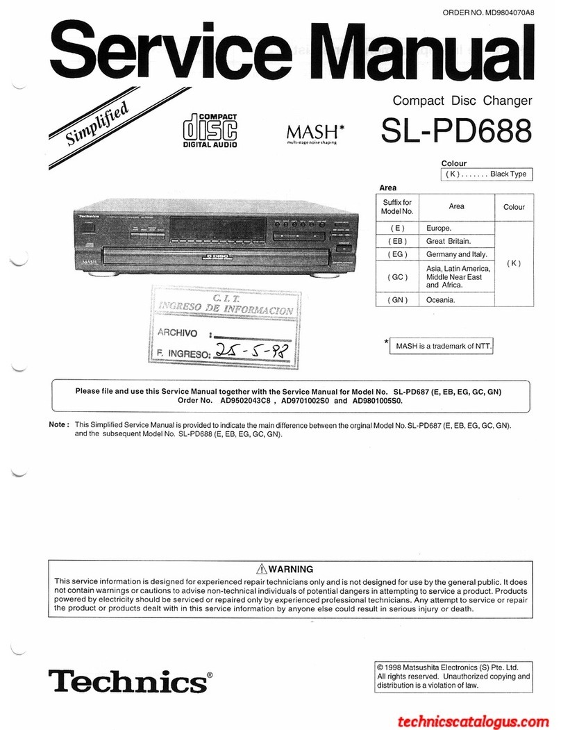
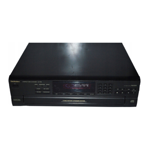
  9. Technics SL-EH60 User manual

Technics SL-EH60 User manual

ORDER
NO.
AD9703028C8
Service
Manual
Compact
Disc
Player
CD
Changer
SL-EH60
System:
SC-EH60
Colour
(KK)
ieseaendeeteietsie
Black
SL-EH60
SH-EH6O
pune
*
SB-PC60
*'
SB-EH60
“
SB-EH60
Area
(E)(EP)
...
Europe,
Russia,
Asia,
Latin
America,
Middle
East,
Africa
and
Oceania.
*
SB-PS60
COMPACT
DIGITAL
AUDIO
Remote
Control
Transmitter
M
A
S
H
#3
multi-
stage
noise
shiping
Because
of
unique
interconnecting
cables,
when
a
component
requires
service,
send
or
bring
in
the
entire
system.
RAE0150Z
MECHANISM
SERIES
Specifications
Audio
Section
General
DA
converter
:
1
bit
DAC
MASH
Dimensions
:
287(W)/89(H\/336(D)
mm
‘
.
ight
:
2.4k
Pickup
Section
werent
ss
Wavelength
:
coon
Notes
:
Specifications
are
subject
to
change
without
notice.
Weight
and
dimensions
are
approximate.
System/SC-EH60:
Sound
processor:
SH-EH60,
Tuner/Amplifier:
SA-EH60,
Compact
disc
changer:
SL-EH60,
Cassette
deck:
RS-EH6
0,
Front
speakers:
*'
SB-EH60,
Center
speaker:
*?
SB-PC60,
Surround
speakers:
*?
SB-PS60
Notes:
*1...For
Europe
and
Russia
:
Made
in
PAES,
For
others
:
Made
in
MESA
*2...Made
in
MESA
*3...MASH
is
a
trademark
of
NTT
Z\WARNING
This
service
information
is
designed
for
experienced
repair
technicians
only
and
is
not
designed
for
use
by
the
general
public.|t
does
not
contain
warnings
or
cautions
to
advise
non-technical
individuals
of
potential
dangers
in
attempting
to
service
a
product.
Products
powered
by
electricity
should
be
serviced
or
repaired
only
by
experienced
professional
technicians.
Any
attempt
to
service
or
repair
the
product
or
products
dealt
with
in
this
service
information
by
anyone
else
could
result
in
serious
injury
or
death.
Technics
©
1997
Matsushita
Electric
Industial
Co.,
Ltd.
All
rights
reserved.
Unauthorized
copying
and
distribution
is
a
violation
of
law.
;
E
3
:
3
3
F
One
Meee
eT
SL-EH60
|
|_|
Contents
Page
Page
Handling
Precautions
for
Traverse
DeCK
.......ccecscssssssesccnseersensesteeseees
2
Type
Illustration
of
IC's,
Transistors
and
Diodes
.............cceccseeneeee
28
Precaution
of
Laser
Diode
...........ccseeeeeee
2,3
Wiring
Connection
Diagram
Location
Of
Controls
..........cceseessccesceseserseeessseacsesscsenseccassseeeesneseneesnenss
3
Terminal
Function
of
(C'S
00...
eeceecscceetseeseceteesenseeaessesaceateessenses
How
to
Set
the
“Transport
Mode?
..........ccsecsscesesseseesesecsessesseeneneeesseensees
3
Troubleshooting
GUIdE
0...
ceseeeesetseseeesesesseesesenscesreneeete
Listen
to
Compact
DiSCS
«0.0...
ceeessssseseereeseessesseesesessesessseeseeseaeeetes
4,5
Block
Diagram
...........
eee
BS
Operation
Checks
and
Replacement
Parts
List
(Electrical)
0.0...
cssessteeseeseetesessensenseeseees
Main
Component
Replacement
Procedures
.........ccscsesseeees
6~17
Resistors
and
Capacitors
........cccscseseeessseeseecereeeeeteenee
..
37,
38
Error
Code
Display
and
Servo
Adjustment
Function
.. ..
18,
19
Replacement
Parts
List
(Cabinet
and
Loading
Unit)
«0.0.0.0...
eee
39
To
Supply
Power
SOuUrce
........ccececcceseeeseeseseecessersscceessesesesseesssenensenes
20
Cabinet
Parts
Location
........cccccsccssscessscssencetesseersescesscesseetsersesneessees
40
Schematic
Diagram
........ee
~21~25
Loading
Unit
Parts
Location
.........c.ccscesccssesssssssessesessesseerensessesneesnennes
41
Printed
Circuit
Board
Diagram
.......cesecssesessesseseseeeeresseeenseeeees
26,
27
NOTE:
Refer
to
the
service
manual
for
Model
No.
SA-EH60
(ORDER
No.
AD9703048C8)
for
information
on
“Accessories”,
“Connections”,
“Installation”,
and
“Packaging”.
CAUTION:
THIS
PRODUCT
UTILIZES
A
LASER.
USE
OF
CONTROLS
OR
ADJUSTMENTS
OR
PERFORMANCE
OF
PROCEDURES
OTHER
THAN
THOSE
SPECIFIED
HEREIN
MAY
RESULT
IN
HAZARDOUS
RADIATION
EXPOSURE.
@
Handling
Precautions
for
Traverse
Deck
The
laser
diode
in
the
traverse
deck
(optical
pickup)
may
break
down
due
to
potential
difference
caused
by
static
electricity
of
clothes
or
human
body.
So,
be
careful
of
electrostatic
breakdown
during
repair
of
the
traverse
deck
(optical
pickup).
©
Handling
of
traverse
deck
(optical
pickup)
1.
Do
not
subject
the
traverse
deck
(optical
pickup)
to
static
electricity
as
it
is
FFC
board
extremely
sensitive
to
electrical
shock.
(Handle
it
carefully)
2.
To
protect
the
laser
diode
against
electrostatic
breakdown,
short
the
flexible
board
(FFC
board)
with
a
clip
or
similar
object.
3.
Take
care
not
to
apply
excessive
stress
to
the
flexible
board
(FFC
board).
4.
Do
not
turn
the
variable
resistor
(laser
power
adjustment).
It
has
already
been
adjusted.
®
Grounding
for
electrostatic
breakdown
prevention
1.
Human
body
grounding
Use
the
anti-static
wrist
strap
to
discharge
the
static
electricity
from
your
body.
2.
Work
table
grounding
Put
a
conducive
material
(sheet)
or
steel
sheet
on
the
area
where
the
traverse
deck
(optical
pickup)
is
placed,
and
ground
the
sheet.
Caution:
The
static
electricity
of
your
clothes
will
not
be
grounded
through
the
wrist
strap.
So,
take
care
not
to
let
your
clothes
touch
the
traverse
deck
(optical
pickup).
Lens
(Do
not
touch)
Variable
resistor
(Do
not
turn)
Caution
when
Replacing
the
Traverse
Deck:
The
traverse
deck
has
a
short
point
shorted
with
solder
to
protect
the
laser
diode
against
electrostatic
breakdown.
Be
sure
to
remove
the
solder
from
the
short
point
before
making
connections.
Wrist
strap
(Anti-static
bracelet)
/
conduct
electricity
1MQ
@
Precaution
of
Laser
Diode
CAUTION:
This
product
utilizes
a
laser
diode
with
the
unit
turned
“on”,
invisible
laser
radiation
is
emitted
from
the
pick
up
lens.
Wave
length:
780
nm
Maximum
output
radiation
power
from
pick
up:
100
h»W/VVDE
Laser
radiation
from
the
pick
up
unit
is
safety
level,
but
be
sure
the
followings:
1.
Do
not
disassemble
the
pick
up
unit,
since
radiation
from
exposed
laser
diode
is
dangerous.
2.
Do
not
adjust
the
variable
resistor
on
the
pick
up
unit.
It
was
already
adjusted.
3.
Do
not lock
at
the
focus
lens
using
optical
instruments.
4.
Recommend
not
to
lock
at
pick
up
lens
for
a
long
time.
ACHTUNG:
Dieses
produkt
enthalt
eine
laserdiode.
Im
eingeschalteten
zustand
wird
unsichtbare
laserstrahlung
von
der
lasereinheit
adgestrahit.
Wellenlange:
780
nm
Maximale
strahlungsleistung
der
laserinhelt:
100
p»W/VDE
Die
strahlung
an
der
lasereinheit
ist
ungefahrllch,
wenn
folgende
punkte
beachtet
werden:
1.
Die
lasereinheit
nicht
zerlegen,
da
die
strahlung
an
der
freigelegten
laserdiode
gefahriich
ist.
2.
Den
werksseitig
justierten
einstellregler
der
lasereinreit
nicht
verstellen.
3.
Nicht
mit
optischen
instrumenten
in
die
fokussierlinse
blicken.
4.
Nicht
ber
langere
zeit
in
die
fokussierlinse
blicken.
0S
|
SL-EH60
CLASS
1
LASER
PRODUCT
INVISIBLE
LASER
RADIATION
WHEN
OPEN.
DANGER
AVOID
DIRECT
EXPOSURE
TO
BEAM.
ADVERSEL
USYNLIG
LASERSTRALING
VED
ABNING
SIKKERHEDSAFBRYDERE
ERUDE
AF
FUNKTION.
UNDGA
UDS/ETTELSE
FOR
STRALING.
VARO!
AVATTAESSA
JA
SUOJALUKITUS
OHITETTAESSA
OLET
ALTTIINA
:
NAKYMATONTA
LASERSATEILYLLE.
ALA
KATSO
SATEESEEN.
VARNING
__OSYNLIGLASERSTRALNING
NAR
DENNA
DEL
AR
OPPNAD
OCH
SPAREN
ARURKOPPLAD.
_BETRAKTA
EJ
STRALEN,
ADVARSEL
USYNLIG
LASERSTRALING
NAR
DEKSEL
APNES
0G
SIKKERHEDSLAS
BRYTES.
UNNGA
EKSPONERING
FOR
STRALEN.
VORSICHT
UNSICHTBARE
LASERSTRAHLUNG,
WENN
ABDECKUNG
GEOFFNET.
NICHT
DEM
STRAHL
AUSSETZEN.
@)
Disc
tray
@
Stop
button
(
#
)
@)
Play
button
and
indicator
([>)
@
Pause
button
(11)
©)
Skip/search
buttons
(
Ke
/
<<
,
>>
/
PP
)
Random
play
button
(RANDOM)
@
Repeat
button
(REPEAT)
Al
edit
button
(Al
EDIT)
@
Dise
check
button
(
4
-NEXT/-AUTO)
m@
How
to
Set
the
“Transport
Mode”
When
the
alignment
of
the
unit
is
finished,
please
make
sure
to
set
it
to
the
“Transport
Mode”
as
following
procedures;
1.
Take
all
CDs
out
from
the
unit.
2.
With
pressing
the
STOP
key
for
more
than
6
seconds.
The
traverse
unit
is
lifted
up
to
the
top
place,
and
all
the
disc
trays
are
fixed
automatically.
3.
Turn
the
unit
off.
NOTE:
The
next
time
the
unit
is
turned
on,
the
“Transport
Mode”
is
automatically
cancelled.
©
Disc
tray
open/close
button
(
4
,
OPEN/CLOSE)
@
Disc
select
buttons
and
indicators
(DISC,
1-5)
SL-EH60
|
@
Listening
to
Compact
Discs
Always
stop
the
changer
before
loading
or
changing
CDs.
You
can-
not
change
CDs
while
a
disc
is
playing.
[—=S/
=
e
=
|
|
HowtoloadCDs
si
to
load
CDs
il
Press
DISC
1-5,
whichever
you
want
to
open.
2
Press
4
OPEN/CLOSE.
EK}
Set
the
CD
in
the
tray.
Press
&
OPEN/CLOSE.
The
tray
will
close.
5)
To
load
other
CDs,
repeat
steps
{J
through
EJ.
About
disc
indicators:
The
indicator
lights
as
follows.
Green:
Indicates
that
the
tray
is
ready
to
play
its
CD
or
to
be
opened.
Orange:
Indicates
that
the
tray
is
in
a
status
other
than
that
described
above.
How
to
check
which
trays
have
discs
&
-NEXT/-AUTO
is
a
convenient
button
to
use
for
this
function.
OPEN/CLOSE
aL
Press
&
-NEXT/-AUTO.
a
The
first
tray
to
open
will
be
the
next
one
after
the
disc
number
shown
2
on
the
display.
For
example,
when
disc
4
is
displayed,
tray
5
will
open.
®
Every
time
you
press
the
button,
the
next
tray
opens.
fe
®You
can
change
the
CD
while
the
tray
is
open.
Label
must
,
®To
close
the
tray,
press
4
OPEN/CLOSE.
face
upward.
ie
Press
and
hold
&
-NEXT/-AUTO.
The
trays
will
open
(and
close)
automatically
one
after
another.
The
first
tray
to
open
will
be
the
next
one
after
the
disc
number
shown
on
the
display.
This
way,
you
can
check
all
trays
ina
row.
eed
®To
stop
the
auto
check
in
course,
press
@.
Discnumber
Total
playingtime
f-
|
Note
|
4
Do
not
attempt
to
change
CDs
while
trays
are
opening
and
closing
in
the
auto
check.
|
To
prevent
damage
|
Always
observe
the
following
points.
®Load
only
1
CD
per
tray.
ZI
®Load
CDs
as
shown
in
figure
FE.
An
adapter
is
not
needed
with
8
cm
CDs
(singles).
®Set
the
system
on
a
flat,
level
surface.
Do
not
set
it
on
top
of
magazines,
inclined
surfaces,
etc.
®Do
not
move
the
system
while
trays
are
opening/closing,
or
when
loaded.
Always
unload
all
trays
before
moving
the
system.
®Do
not
put
anything
except
CDs
in
trays.
Do
not
use
cleaning
CDs
or
CDs
which
are
badly
warped
or
cracked.
®Do
not
use
CDs
with
poorly
attached
labels
or
stickers.
Ad
hesive
protruding
from
underneath
stickers
or
left
over
from
peeled
off
stickers
can
cause
the
system
to
malfunction.
STANDBY
Discnumber
Total
playing
time
a
OPEN/CLOSE
pa
(Ct)
SL-EH60
Sequential
play
il
Switch
on
the
power.
2
Insert
CDs
in
the
trays.
When
the
“CD”
input
source
is
selected,
disc
number,
total
number
of
tracks,
and
total
playing
time
will
appear
on
the
display.
When
there
are
16
or
more
tracks
on
the
CD,
“
=>”
will
appear.
The
total
playing
time
displayed
when
a
disc
is
loaded
includes
intervals
between
tracks.
This
is
why
sometimes
the
displayed
time
is
longer
than
that
listed
on
the
CD.
fk]
Press
>.
The
changer
will
automatically
play
all
tracks
on
all
discs.
It
will
start
from
the
first
track
on
the
disc
shown
on
the
display,
and
will
continue
until
playing
the
last
track
of
the
final
disc
(see
below).
4
Adjust
the
volume
level
as
you
like.
To
stop
the
disc
play:
Press
@.
To
temporarily
stop
the
disc
play:
Press
88.
The
play
indicator
flashes
green.
To
play
again,
press
>.
What
is
meant
by
“final
disc”?:
For
example,
if
play
starts
from
disc
4,
disc
3
will
be
the
“final
disc”.
Order
of
progression:
Disc
4»
5»
1-»2-3
About
play
indicator:
While
halted:
Lights
up
orange.
While
playing:
Lights
up
green.
For
your
reference:
If
you
press
>
instead
of
&
OPEN/CLOSE
after
insertinga
CD,
the
tray
will
close
and
play
will
start
directly
from
the
track
1.
To
search
forward/
Hold
down
during
playback.
backward
[
/<44|[
>>
/
pr!
(Backward)
(Forward)
To
skip
forward/
Press.
backward
[e/a
|
[>>
/pr-|
(Backward)
(Forward)
During
random
play,
you
cannot
skip
to
tracks
which
hate
already
been
played.
For
your
reference:
©
During
program
play
or
random
play,
you
cannot
searchforward/
backward
over
tracks.
®During
program
play,
skipping
is
in
always
in
the
pregrarmmed
order,
whether
forward
or
backward.
One-touch
play
BJ
When
the
system
is
OFF,
playing
starts
automatically
when
you
press
®
on
the
remote
control.
The
play
will
start
with
volume
increasing
gradually.
|
!
|
|
SL-EH60
|
Mi
Operation
Checks
and
Main
Component
Replacement
Procedures
ete
4.
This
section
describes
procedures
for
checking
the
operation
of
the
major
printed
circuit
boards
and
replacing
the
main
components.
2.
For
reassembly
after
operation
checks
or
replacement,
reverse
the
respective
procedures.
Special
reassembly
procedures
are
described
only
when
required.
3.
Select
items
from
the
following
index
when
checks
or
replacement
are
required.
4.
Refer
the
parts
No.
on
the
page
of
“Main
Component
Replacement
Procedures”,
if
necessary.
e
Contents
*
CD
Changer
Disassembly
/
Reassembly
page.
1.
Removal
for
the
CD
changer
Unit.
seeeeccreescccccecccccceccesccccccsccvessccesevescce
6,7.
2.
Removal
for
the
traverse
UNit.
secre
eeccecccesececccesssccesecseseccsccccccesesesoscess
&
3.
Disassembly
for
the
CD
changer
Unit.
ssseseesesseseecscccseccccsscccscccsesscscevecnsese
BY,
4.
Reassembly
for
the
CD
changer
unit.
s*+sssesseeccscecccrccccccsccccsccscsesececceesce
I~
13,
5.
Inspection
for
the
CD
changer
unit.
Cero
e
creer
eaneeccesssereseseeeeeseceeeeeeseeseseeseety
*
Checking
Procedures
for
each
P.C.B.
1.
Checking
for
the
main
P.C.B..csereccrereeesccsscccsscscccscccccesscscccesscsvcvesssce
sd,
2.
Checking
for
the
operation
P.C.B..
Cee
e
reece
rerereeeeseeseesreeeseeeeeHeseeeeeeeeeeDeeeD
14,15.
3.
Checking
for
the
servo
P.C.B..eeeeeeceseresereesccssececcsccessccesessescvccsececes
15,16,
*
Main
Component
Replacement
Procedures
1.
Replacement
for
the
traverse
deck
ass'y.seeeeesessercoccscccsccsccscccsscescccesecesee
i647,
Hi
CD
Changer
Disassembly
/
Reassembly
1.
Removal
for
the
CD
changer
unit
Remove
the
5
screws.
Remove
the
top
cabinet.
Top
cabinet
Release
the
6
claws,
and
then
remove
the
front
panel
ass’y.
|
SL-EH60
Pull
out
the
FFC
(2
points).
Remove
the
2
screws.
Connector
4
(CN401)
2
Remove
the
2
screws.
Reinforcing
angle
Remove
the
reinforcing
angle.
vy
LED
holder
Release
the
2
claws,
and
then
removethe
LED
holder.
CD
changer
vy
The
CD
changer
unit
will
be
removed.
CD
changer
SL-EH60
|
2.
Removal
for
the
traverse
unit
NOTE
Lock
lever
(L)
Locate
the
traverse
unit
to
the
position
“DOWN”.
(Rotate
the
drive
gear
in
the
direction
of
arrow
so
that
the
position
is
“DOWN”.)
©
Slide
plate
2
Lock
lever
(S)
(Back
side
of
CD
changer
mechanism)
Slide
plate
1
Procedures
Qed
|
Push
the
lock
lever
(S)
with
lifting
the
claw,
and
then
push
the
lock
lever
(L)
in
the
direction
of
arrow
(=).
Refer
to
the
figures
@)and
@).
CSW)
|
The
slide
plate
1
and
2
of
traverse
retain
boss
€)
and
@
are
open.
Refer
to
the
figures
©and®).
GED
|
Push
the
traverse
unit
in
the
direction
of
arrow
(=).
(The
FFC
is
connected.)
Lb
GEEZ)
|
The
traverse
unit
will
be
removed.
3.
Disassembly
for
the
CD
changer
unit
NOTE
Locate
the
traverse
unit
to
the
position
“DOWN”.
GED
|
Release
the
2
claws,
and
then
remove
the
switch
P.C.B..
Remove
the
6
screws.
Switch
P.C.B.
|_
steno
Vv
Vv
Mechanism
cavercssy
@SED
|
Remove
the
mechanism
cover
ass’y.
DO
4
disc
trays
contacted
to
the
mechanism
cover
ass’y
will
be
removed.
1
disc
tray
is
removed
to
the
mechanism
base
ass’y.
GEEZ)
|
Remove
the
disc
tray
sided
mechanism
base
ass’y.
Mechanism
base
ass'y
Base
lock
lever
GED
|
Unlock
the
base
lock
lever.
Tray
base
Mechanism
base
ass'y
Stopper
Release
the
stopper
manually.
Draw
the
tray
base.
D
In
case
that
the
tray
base
can
not
be
open
due
to
hooking,
draw
the
tray
base
with
finger
pressing
the
back
side
indicated
by
(">
of
base.
(Take
care
handling
of
stopper.)
@
Take
care
not
avoid
the
carrier
lock
lever
spring.
The
belt
and
each
part
can
be
replaced
after
Stopper
above
procedures
are
performed.
SL-EH60
|
4.
Reassembly
for
the
CD
changer
unit
(Back
side)
GERD
|
Pull
the
drive
rack
in
the
direction
of
arrow
(=>)
Drive
rack
Slide
the
carrier
in
the
direction
of
arrow
(=).
Tray
base
End
of
carrier
Carrier
lock
lever
(Tray
base
side)
O
Lock
the
lever.
Insert
the
tray
base
to
the
mechanism
base
ass’y
with
keeping
the
procedures
and
Ge.
Tray
base
Drive
rack
Tray
base
Marking
“p>”
Drive
gear
Pulley
gear
Tray
base
Projection
Stopper
|
SL-EH60
Insert
the
drive
rack
until
the
driver
rack
interferes
with
the
drive
gear.
Position
@
ZED
||
Rotate
the
pulley
gear
clockwise
gently
by
hand
(5
or
6
times).
@
When
the
gear
begins
to
rotate,
rotate
the
pulley
gear
with
finger
pressure
(position
®
)
because
the
drive
rack
gear
will
fall
free.
vy
Gx
|
Allow
the
tray
base
be
open
manually.
*
Draw
the
inserted
tray
base
forward.
\y
Locate
the
projection
at
the
marking
“BP”
as
shown
left.
D
In
case
that
the
stated
above
is
not
operated
draw
the
tray
base
again.
(Refer
to
item
(1)
on
page
9)
(Retry
the
item
marked
with
@)
Tray
base
-~11-
SL-EH60
|
While
lifting
the
claw
upward,
press
the
lock
lever
(L)
with
forcing
the
lock
lever
(S).
@2ED
|
Align
the
boss
of
traverse
unit
with
the
groove
Lock
lever
(S)
ay
Lock
lever
(L)
of
mechanism
base
ass’y.
7
@@SR
|
Pull
the
lock
lever
(L)
in
the
direction
of
Lock
lever
(L
@
Release
the
lock
lever
”
manually.
Traverse
unit
@
Rotate
the
conversion
lever
manually.
(“DOWN
’stated)
-12-
arrow
(=).
After
assembly,
confirm
the
traverse
unit
operation.
(“UP’stated)
SL-EH60
Disc
tray
No.2
L}
Disc
tray
No.3
ESD
|
Install
the
4
disc
trays
to
the
mechanism
cover
ass’y.
(Allow
them
to
lock
with
claws.)
Disc
tray
No.4
Disc
tray
No.5
®
Install
the
disc
trays
in
specific
order.
(Disc
tray
No.
is
indicated
on
the
tray.)
Carrier
arm
EMEP
|
Place
the
disc
tray
No.1
on
the
mechanism
base
ass’y.
Mechanism
cover
ass’y
ESE)
|
Install
the
mechanism
cover
ass’y.
i}
i
< .
pie
(D))
The
carrier
arm
is
positioned
as
shown
left.
‘yi
Disc
tray
No.1
Carrier
arm
a—
Mechanism
base
ass’y
5.Inspection
for
the
CD
changer
unit
*
Begin
the
inspections
in
condition
that
the
traverse
is
kept
:
;
from
disc
tray.
(5
disc
trays
in
the
store
compartment.)
3
Manual
operations
CD
changer
unit
Rotate
the
drive
gear
counterclockwise
manually.
®
The
tray
base
is
closed,
and
then
it
retuins
to
start
position.
~13-
SL-EH60
|
i
Checking
Procedures
for
each
P.C.B.
1.
Checking
for
the
main
P.C.B.
Perform
the
items
GSR
and
G8)
for
CD
changer
removal
(Refer
to
page
6.)
a
oe
fa)
x4
Main
P.C.B.
Lead
wire
Shield
plate
Grounding
plate
Operation
P.C.B.
Remove
the
4
screws.
step
2
J
Remove
the
4
claws,
and
then
stand
the
main
P.C.B..
Connect
the
lead
wire
between
the
grounding
plate
and
shield
plate.
Check
the
main
P.C.B.
(solder
side)
as
shown
left.
cup
Release
the
3
claws,
and
then
upset
the
operation
P.C.B..
|
SL-EH60
Check
the
operation
P.C.B.
(solder
side)
as
shown
left.
Operation
P.C.B.
(Solder
side)
3.
Checking
for
the
servo
P.C.B.
Perform
the
items
~
for
CD
changer
removal
(Refer
to
pages
6
and
7.)
vy
Perform
the
items
@&—
~
G@SZ)
for
traverse
unit
removal
(Refer
to
page
8.)
wer
CD
changer
unit
GED
|
Install
the
CD
changer
unit
to
the
set.
D
Screw
tighten
is
not
necessary.
Connect
the
FFC
to
the
connector
(CN401).
Remove
the
rubber.
Connector
(CN401)
@2ZD
|
Align
the
hook
of
traverse
unit
with
the
slot,
and
Traverse
unit
as
then
stand
it.
GBD
|
Attach
the
disc
and
clamper
with
magnet
to
the
traverse
unit.
®
Prepare
the
clamper
used
ordinaly.
Connector
|
oe
sf
Connect
the
FFC
to
the
connector
(CN402).
(CN402)
~15-
SL-EH60
2X
Take
care
Apply
the
tape
between
the
chassis
and
not
to
contact
‘
.
. .
to
the
chassis.
traverse
unit
not
to
contact
the
disc
with
chassis.
Chassis
Check
the
servo
P.C.B.
(solder
side)
Servo
P.C.B.
as
shown
left.
1.
Replacement
for
the
traverse
deck
ass’y
Perform
the
items
GED
~
for
CD
changer
removal
(Refer
to
pages
6
and
7.)
=
Remove
the
3
screws.
Unsolder
the
motor
terminals.
Solder
Solder
J
Servo
P.C.B.
GED
|
Remove
the
FFC
from
the
connector,
and
then
remove
the
servo
P.C.B..
Caution:
Insert
a
short
pin
into
the
traverse
unit
FFC
board.
Refer
to
“Hnading
Precautions
for
raverse
Deck”
on
page
2.)
Top
of
the
connector
FFC
FFC
board
v4
i
aD
>
Short
pin
=46)=
|
SL-EH60
GEZD
|
Remove
the
pins.
1.
Spread
the
boss
2.
Pull
out
the
pin
in
the
with
©
screwdriver.
direction
of
arrow.
©
screwdriver
Pin
Boss
aly
&
7
Traverse
deck
ass’y
[RAE0150Z]
GED
|
Release
the
claws,
and
then
remove
the
traverse
deck
ass’y.
ae)
Be
careful
not
to
lose
the
3
springs
because
those
will
also
be
removed
on
removal
of
the
traverse
deck
ass’y.
Floating
spring
(1)
Floating
spring
(2)
GEED
|
Before
installing
the
servo
P.C.B.,
move
the
optical
pickup
toward
the
outer
edge
from
mark
“<@”,
O
In
case
that
the
optical
pickup
is
not
moved
toward
the
outer
edge
from
the
marking,
the
rest
detect
switch
(S701)
mounted
on
the
servo
P.C.B.
may
be
damaged.
Rest
det.
switch
BS
)
Connector
j
|
(CN701)
@
After
tightening
screws,
solder
each
motor
terminal.
Optical
pickup
T
Marking
“<4”
,
we
"
>
Rotate
the
gear
to
move
Motor
terminals
it
:
the
side
A
of
optical
pickup
toward
the
outer
Optical
pickup
edge
from
the
marking
“<q”.
SL-EH60
|
m@
Error
Code
Display
and
Servo
Adjustment
Function
This
unit
has
an
error
code
display
function,
so
that
if
the
unit
operates
incorrectly,
the
fault
is
displayed
using
an
error
code
on
the
FL
display
of
the
Tuner/Amplifier
(SA-EH60).
It
also
has
a
servo
adjustment
function
for
displaying
the
status
of
servo
system
functions
(Focus,
Tracking,
CLV
Servo)
on
the
FL
display
of
the
Tuner/Amplifier.
The
system
control
IC
and
FL
display
are
part
of
the
Tuner/Amplifier
so
make
sure
the
system
has
been
connected
properly
before
using
three
functions.
(This
unit
can
be
operated
independently,
although
the
error
code
display
and
servo
adjustment
functions
cannot
be
used.)
Use
these
two
functions
for
guidance
during
fault
diagnosis
and
repair.
Note:
Check
beforehand
for
scratching
or
soiling
of
the
test
disc
(SZZP1054C),
and
soiling
or
other
problems
with
the
pickup
lens.
e
Error
code
display
procedure
Automatic
adjustment
results
Checking
the
mechanism
switches
Turn
the
power
ON.
Press
the
F.
SKIP
button.
Hold
down
the
REPEAT
button
for
at
least
2
seconds,
and
then
Load
the
test
disc
(SZZP1054C).
A
mechanism
OK/NG
error
code
is
displayed.
(See
Table
1.)
This
error
code
can
be
used
diagnose
whether
or
not
the
mecha-
nism
is
OK.
If
there
are
multiple
errors,
these
can
be
displayed
successively
by
pressing
the
F.
SKIP
button.
press
the
STOP
button
for
at
least
2
seconds
while
continuing
to
hold
down
the
REPEAT
button.
Remove
the
disc
and
turn
the
power
OFF.
(The
error
code
display
mode
is
canceled.)
A
servo
section
error
code
is
displayed.
(See
Table
2.)
Use
this
error
code
display
as
a guideline
for
finding
the
malfunction
point
in
the
servo
circuitry.
If
the
error
code
“E-00”
is
displayed,
the
unit
is
“OK
(No
problem).”
@
Servo
adjustment
procedure
Turn
the
power
ON.
Load
the
test
disc
(SZZP1054C).
Hold
down
the
REPEAT
button
for
at
least
2
seconds,
and
then
press
the
PAUSE
button
for
at
least
2
seconds
while
continuing
to
hold
down
the
REPEAT
button.
Press
the
B»
(PLAY)
button,
and
play
for
10
seconds.
Servo
adjustment
results
are
displayed.
(Example)
—
Normal
Focus
Tracking
CLV
servo
ity
a
Hagete
“H"
level
“L”
level
Remove
the
disc
and
turn
the
power
OFF.
ee
euvsenoayeen
|
aetcive
|
normal
~18-
SL-EH60
@
Table
1
[15
[men
covayenomnonesbyiseh
|
ce
a
[15
_[osenotny
een
wren
CO
pi
unis
pessoa
‘|
Peaprntabtonanesion
owen
SoH
———_—|
[16
[Teveseneeewascre,
=i
tneanctonawmen
sot
=|
|
F268
Does
not
move
even
when
“b>”
(PLAY)
button
is
pressed.
Tray
keeps
moving
for
a
while,
or
selected
tray
does
not
open.
@
Table
2
*
The
unit
is
satisfactory
if
the
error
code
is
“E-00”
or
“E02”.
*
Before
testing,
check
that
the
test
disc
is
free
of
scratches
and
optical
pickup
is
clean.
Disc
tray
“Open”
detection
switch
(S4)
fault.
FL
error
Signal
to
check
Normal
voltage
and
waveform
values
code
Symptom
Probable
cause
Signal
display
Location
Ree
PLAY
STOP
PLAY
_
1C702
8)
pin
MDATA
pine
Mey
T=13.6
ms.
Focus
and
tracking
|
®Clocks
X1
and
X2,
power
supply
Vop,
and
PLAY
offset
adjustments
|
reset
(/RST),
all
on
IC702.
=e
”
not
completed
in
|@MDATA,
MCLK,
MLD,
and
SENSE
signals
0
v
specified
time
to/from
mechanism
controller.
period.
IC702
i
vis
Ses
F=16.9344
MHz
PLAY
:
0.3Vp-p
IC702
@2
pin
Eo
2ms.
0.1
VD.
1
Hs
PLAY
@Scratches
or
contaminants
on
disc
surface
I¢702
3
pin
[osvep
2
ms.
0.2
V/DIV.
@Focus
and
Tracking
servo
circuits
(check
Disc
play
unstable
|
waveforms,
voltages,
and
part
values.)
@Spindle
driver
circuit
@Optical
pickup
(e702
pn
_|
STAT
oe
rata
im
@Scratches
or
contaminants
on
disc
surface
ae:
os
04
i:
conipleted
in
@Focus
servo
circuit
(check
waveforms,
rn
ie
apecified
time
voltages,
and
part
values.)
P
nay:
period.
@phealipiceup
OFT
/TLOCK
-19-
SL-EH60
|
@
To
Supply
Power
Source
Cautions:
@
It
is
very
dangerous
to
look
at
or
touch
the
laser
beam.
(Laser
radiation
is
invisible.)
With
the
unit
turned
“on”,
laser
radiation
is
emitted
from
the
pickup
lens.
@
Avoid
exposure
to
the
laser
beam,
especially
when
performing
adjustments.
This
unit
SL-EH60
is
designed
to
operate
on
power
supplied
from
the
Tuner/Amplifier
(SA-EH60)
through
the
Cassette
Deck
RS-
EH60.
When
connecting
the
unit
to
other
system
components,
do
not
connect
to
the
Tuner/Amplifier
SA-EH60
directly.
Be
sure
to
connect
this
unit
through
the
Cassette
Deck
RS-EH60.
When
operating
the
unit
SL-EH60
alone
for
testing
and
servicing,
without
having
power
supplied
from
the
Tuner/Amplifier
SA-EH60
and
the
Cassette
Deck
RS-EH60,
use
the
following
method.
Power
Supply
to
This
Unit
Alone
Apply
+10
V
DC
power
to
the
section
between
L1
(BXegRW)
and
€1({E{Ns)).
(Shown
in
Fig.1)
To
Check
Signals
Connect
the
oscilloscope
or
the
speaker
with
built-in
amplifier
to
the
section
between
LINE
OUT
(L-ch)
of
the
resistor
R447
and
the
as
well
as
the
section
between
LINE
OUT
(R-ch)
of
the
resistor
R448
and
the
and
check
if
the
signals
are
outputting
from
this
unit.
(Shown
in
Fig.
1)
Main
P.C.B.
R447
LINE
OUT
(L-ch)
(Signak
check)
R448
LINE
OUT
(R-ch)
(Signak
check)
Fig.
1
90

Other Technics CD Player manuals

Technics SL-PS7 User manual

Technics

Technics SL-PS7 User manual

Technics SL-XP505 User manual

Technics

Technics SL-XP505 User manual

Technics SL-PC14 User manual

Technics

Technics SL-PC14 User manual

Technics SL-P1300 User manual

Technics

Technics SL-P1300 User manual

Technics SL-PG350 User manual

Technics

Technics SL-PG350 User manual

Technics sl-mc410 User manual

Technics

Technics sl-mc410 User manual

Technics SL-PD988 User manual

Technics

Technics SL-PD988 User manual

Technics SLPD6 - COMPACT DISC CHANGER User manual

Technics

Technics SLPD6 - COMPACT DISC CHANGER User manual

Technics SL-PG340 User manual

Technics

Technics SL-PG340 User manual

Technics S-PG340 User manual

Technics

Technics S-PG340 User manual

Technics SL-PG540A - service User manual

Technics

Technics SL-PG540A - service User manual

Technics sl-pd887 User manual

Technics

Technics sl-pd887 User manual

Technics SL-PG520A User manual

Technics

Technics SL-PG520A User manual

Technics SL-XP600 User manual

Technics

Technics SL-XP600 User manual

Technics sl-pd887 User manual

Technics

Technics sl-pd887 User manual

Technics SL-XP140 User manual

Technics

Technics SL-XP140 User manual

Technics SL-PG440A User manual

Technics

Technics SL-PG440A User manual

Technics SL-XP700 User manual

Technics

Technics SL-XP700 User manual

Technics SLMC7 - COMPACT DISC CHANGER User manual

Technics

Technics SLMC7 - COMPACT DISC CHANGER User manual

Technics SL-PD988 User manual

Technics

Technics SL-PD988 User manual

Technics SL-PS840 User manual

Technics

Technics SL-PS840 User manual

Technics SL-MC70 User manual

Technics

Technics SL-MC70 User manual

Technics SL-PS840 User manual

Technics

Technics SL-PS840 User manual

Technics SL-C700E User manual

Technics

Technics SL-C700E User manual

Popular CD Player manuals by other brands

Kenwood DPC-321 instruction manual

Kenwood

Kenwood DPC-321 instruction manual

Philips D 8892 operating instructions

Philips

Philips D 8892 operating instructions

Aiwa Z8RDLC Service manual

Aiwa

Aiwa Z8RDLC Service manual

Philips CD723/20 Instructions for use

Philips

Philips CD723/20 Instructions for use

Scott SMV300 owner's manual

Scott

Scott SMV300 owner's manual

Hitachi CX-38E user guide

Hitachi

Hitachi CX-38E user guide

moon CD 3.3 owner's manual

moon

moon CD 3.3 owner's manual

Yamaha CD-S3000 owner's manual

Yamaha

Yamaha CD-S3000 owner's manual

Sony CDX-GT360S operating instructions

Sony

Sony CDX-GT360S operating instructions

Pyle Pro PDJ150U owner's manual

Pyle Pro

Pyle Pro PDJ150U owner's manual

Philips AZ 1560/00 Specifications

Philips

Philips AZ 1560/00 Specifications

Philips CDI 180 Installation and operation manual

Philips

Philips CDI 180 Installation and operation manual

Philips AZ7881 manual

Philips

Philips AZ7881 manual

Numark 4 Quick start owner's manual

Numark

Numark 4 Quick start owner's manual

JVC RC-EZ31A Service manual

JVC

JVC RC-EZ31A Service manual

Marantz CDR510 user guide

Marantz

Marantz CDR510 user guide

Pioneer CDX-M2086ZBM Service manual

Pioneer

Pioneer CDX-M2086ZBM Service manual

Kenwood DVF-3500-B instruction manual

Kenwood

Kenwood DVF-3500-B instruction manual

manuals.online logo
manuals.online logoBrands
  • About & Mission
  • Contact us
  • Privacy Policy
  • Terms and Conditions

Copyright 2025 Manuals.Online. All Rights Reserved.