Technics SH-8038 User manual

Technics
Stereo Graphic Equalizer
SH-8038
OPERATING INSTRUCTIONS
Before operating this unit, please read these instructions completely.

Technics, The Science of Sound, welcomes the
challenge of new audio technologies and brings you
a multitude of world-renowned, high quality audio
components, all backed by our time-honored com-
mitment to innovation, value, and quality.
Technics captures the power of new ideas and turns
them into high performance components like digital
compact disc players that feature High Speed
Linear Motor Transports, high speed editing cas-
sette decks, professional and consumer turntables,
Computer Drive New Class A amplifiers, and A/V
receivers that integrate both audio and video equip-
ment.
The Technics list of advanced audio components
continues. From Class AA amplifiers, honeycomb
disc speakers, and multi-disc CD changers to the
world's first touch-sensitive graphic equalizer,
Technics is a shining example of audio technology
at its best.
Contents
*Accessories .............................. 2
*Suggestions for Safety .................... 3
*Connections .............................. 4
*Front Panel Controls and Functions ........ 5
*Operation ................................ 6
*Examples of Applications .................. 7
*Troubleshooting Guide .......... back cover
*Technical Specifications ........ back cover
*Maintenance .................... back cover
*Product Service ................ back cover
Accessories
*Stereo connection cables .............................. 2 *AC power supply cord .................................. 1
The model number and serial number of this product can
be found on either the back or the bottom of the unit.
Please note them in the space provided below and retain
this booklet as a permanent record of your purchase to aid
identification in the event of theft.
MODEL NUMBER SERIAL NUMBER
WARNING:
TO REDUCE THE RISK OF FIRE OR ELEC-
TRIC SHOCK, DO NOT EXPOSE THIS AP-
PLIANCE TO RAIN OR MOISTURE.
CAUTION
CAUTION: TO REDUCE THE RISK OF
ELECTRIC SHOCK, DO NOT
REMOVE SCREWS.
NO USER-SERVICEABLE
PARTS INSIDE.
REFER SERVICING TO QUALIFIED
SERVICE PERSONNEL.
The lightning flash with arrowhead symbol,
within an equilateral triangle, is intended to
alert the user to the presence of uninsulated
"dangerous voltage" within the product's
enclosure that may be of sufficient magnitude
to constitute a risk of electric shock to persons.
The exclamation point within an equilateral
triangle is intended to alert the user to the
presence of important operating and main-
tenance (servicing) instructions in the literature
accompanying the appliance.

Suggestions for Safety
Before using this unit, be sure to read applicable items of the
operating instructions and these safety suggestions carefully.
Afterwards keep them handy for future reference. Take special
care to follow the warnings indicated on the unit itself as well as
in the operating instructions.
•Water and Moisture -- The unit should not be used
near water -- for example, near a bathtub, washbowl,
kitchen sink, laundry tub, in a wet basement, or near a
swimming pool, and the like.
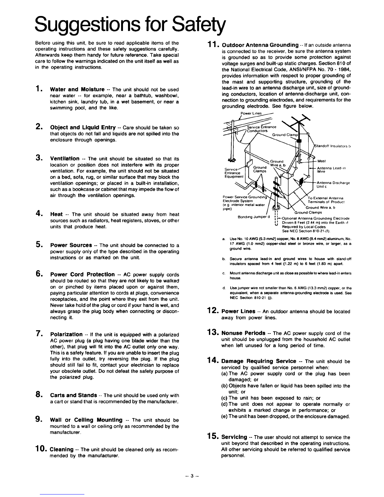
11. Outdoor Antenna Grounding -- If an outside antenna
is connected to the receiver, be sure the antenna system
is grounded so as to provide some protection against
voltage surges and built-up static charges. Section 810 of
the National Electrical Code, ANSI/NFPA No. 70 - 1984,
provides information with respect to proper grounding of
the mast and supporting structure, grounding of the
lead-in wire to an antenna discharge unit, size of ground-
ing conductors, location of antenna-discharge unit, con-
nection to grounding electrodes, and requirements for the
grounding electrode. See figure below.
Power Lines
1Object and Liquid Entry -- Care should be taken so
that objects do not fall and liquids are not spilled into the
enclosure through openings.
=
•
1
1
Ventilation -- The unit should be situated so that its
location or position does not insterfere with its proper
ventilation. For example, the unit should not be situated
on a bed, sofa, rug, or similar surface that may block the
ventilation openings; or placed in a built-in installation,
such as a bookcase or cabinet that may impede the flow of
air through the ventilation openings.
Heat -- The unit should be situated away from heat
sources such as radiators, heat registers, stoves, or other
units that produce heat.
Power Sources -- The unit should be connected to a
power supply only of the type described in the operating
instructions or as marked on the unit.
Power Cord Protection -- AC power supply cords
should be routed so that they are not likely to be walked
on or pinched by items placed upon or against them,
paying particular attention to cords at plugs, convenience
receptacles, and the point where they exit from the unit.
Never take hold of the plug or cord if your hand iswet, and
always grasp the plug body when connecting or discon-
necting it. 12.
Entrance
Equipment
-Antenna Lead II1
Wire
ge
Unit c
Power Service Groundlt To External Antenna
Electrode System Terminals of Product
(e g interior metal water
pipe} Ground Wire a, b
i = Ground Clamps
Bonding Jumper d_ I_Op ional Antenna Grounding Electrode
i i Driven 8 Feet (2.44 m) into the Earth if
uRequired by Local Codes
See NEC Section 810-21 ,(f).
a. Use No. 10 AWG (5.3 mm2) copper, No. 8 AWG (8.4 ram2) aluminum, No.
17 AWG (1.0 ram2) copper-clad steel or bronze wire, or larger, as a
ground wire.
b. Secure antenna lead-in and ground wires to house with stand-off
insulators spaced from 4 feet (1.22 m) to 6 feet (1.83 m) apart.
c. Mount antenna discharge unit as close as possible to where lead-in enters
house.
d. Use jumper wire not smaller than No. 6 AWG (13.3 mm2) copper, or the
equivalent, when a separate antenna-grounding electrode is used. See
NEC Section 810-21 (j).
Power Lines -- An outdoor antenna should be located
away from power lines.
•
•
•
10.
Polarization -- If the unit is equipped with a polarized
AC power plug (a plug having one blade wider than the
other), that plug will fit into the AC outlet only one way.
This is a safety feature. If you are unable to insert the plug
fully into the outlet, try reversing the plug. If the plug
should still fail to fit, contact your electrician to replace
your obsolete outlet. Do not defeat the safety purpose of
the polarized plug.
Carts and Stands -- The unit should be used only with
a cart or stand that is recommended by the manufacturer.
Wall or Ceiling Mounting -- The unit should be
mounted to a wall or ceiling only as recommended by the
manufacturer.
Cleaning -- The unit should be cleaned only as recom-
mended by the manufacturer.
13.
14.
Nonuse Periods -- The AC power supply cord of the
unit should be unplugged from the household AC outlet
when left unused for a long period of time.
Damage Requiring Service -- The unit should be
serviced by qualified service personnel when:
(a)The AC power supply cord or the plug has been
damaged; or
(b) Objects have fallen or liquid has been spilled into the
unit; or
(c) The unit has been exposed to rain; or
(d)The unit does not appear to operate normally or
exhibits a marked change in performance; or
(e) The unit has been dropped, or the enclosure damaged.
15. Servicing -- The user should not attempt to service the
unit beyond that described in the operating instructions.
All other servicing should be referred to qualified service
personnel.
-3-

Connections Refer to the operating instructions of the /
amplifier for further details. J
•Connect to the input/output (EXT OUT/EXT IN) terminals of an integrated amplifier.
Using the connection diagram below, corrected signals from any source can be heard or recorded onto the tape deck.
External output terminals (EXT OUT) I
External input terminals (EXT IN) I
)(R)(L)(R)(L)
Integrated
amplifier (option)
If the amplifier does not have external input/output terminals (EXT
OUT/EXT IN).
•Connect to the -rAPE monitor terminals of an integrated
amplifier.
To the AC outlet of the audio equipment, or household AC outlet.
( Refer to the operating instructions of the amplifier. )
_AC power supply cord
(included)
This unit
(SH-8038)
(R)(L) (R)(L)
Stereo connection _._...___
cables (included)
(L)(R) (L)(R)
"UNSWI'rCHED" outlet: Power is always
available, regardless of power switch set-
ting. Equipment rated up to 150 W can be
connected.
Tape deck
(option)
Note: A receiver or preamplifier can be connected in the same
manner as described above. An integrated amplifier is
used here for example.
CAUTION:
TO PREVENT ELECTRIC SHOCK MATCH WIDE
BLADE OF PLUG TO WIDE SLOT, FULLY IN-
SERT.
Note that the way the input and output cords are routed
(for example, if they are tangled with the power cord)
could cause a hum to be emitted.

Front Panel Controls and Functions
Power switch (power)
This switch turns on and off the secondary circuit power only.
The unit is in the "standby" condition when this switch isset to the "off" (.= _II) position.
Regardless of the switch setting, the primary circuit is always "live" as long as the power cord is
connected to an electrical outlet.
I
Left channel Band-level controls (left)
These levers are used to adjust the 7 frequency levels.
When these levers are moved in the "+ dB" direction, peak frequency
characteristics are obtained. When they are moved in the"- dB" direction,
dip frequency characteristics are obtained. These characteristics can be
adjusted a maximum of _+12 dB.
When the power switch is set to the "on" position, the tip of these levers will
illuminate.
II T
Right channel Band-level controls (right)
These levers function the same as the left channel band-level
controls.
•Equalization switch (equalizer)
This switch is used to turn the equalization circuitry on and off.
on(1_ =):
Set to this position for equalizer correction.
off(=_Jt):
Set to this position to turn off equalizer correction. By turning this switch on and off, the
equalizer effect can also be checked. When this switch is in the "off" (.,=-- l) position,
signals will still pass through the unit and be emitted, regardless of whether the power
switch isin the "on" or "off" position.
• Recording mode selector (rec mode)
straight (a _ In'):
Set to this position to record without equalizer correction.
EO (n __.=,.):
Set to this position to make a tape recording of a radio broadcast or adisc while controlling
the frequeny response.
Note:
The equalization switch must be set to the "on" ( II _.=,.) position and then the input
selector must be set to the "source" (A _II) position, otherwise the frequency response
cannot be controlled.
This only works for tape decks connected to this unit.
.)
•Reverse mode selector (reverse)
off(=_lt):
This is the normal position for use, when set to this position, the sound level of desired frequencies can be raised
or lowered 12 dB by moving the lever in the (+dB) direction or (-dB) direction.
on (l-- =):
When set to this position, characteristics are obtained which are completely inverted with respect to those
obtained in the "off" position.
This isconvenient for purposes such as reducing tape hiss, etc.
•Input selector (input selector)
source (.,,.-- n):
Set to this position to listen to the radio or a compact disc, etc.
tape (11_ =):
Set to this position to listen to a tape deck connected to the back of this unit.
-5-

Operation Note: Turn the amplifier on, and set it for listening to the sound.
(Refer to the operating instructions of the amplifier.)
Reduce the volume level of the amplifier.
Set the amplifier's tone controls to the center position, and set _
the super bass or loudness switch to "OFF".
Set the power switch to "on". Set the tape-monitor selector of the amplifier to
"Tape" position. (Refer to note)
(Refer to the operating instructions of the amplifier for further details.)
Reverse mode selector
This unit
(SH-8038)
To listen to corrected sound of compact disc or radio.
To record the corrected sound of compact disc or from the radio.
To record the uncorrected sound of compact disc or from the radio.
To listen to corrected sound from a tape deck.
4 5 6
equalizer rec mode ;i ........ ctor
m
"on"(l--_)
Setto any position.
"EQ"(I--_)
_ "straight" (__ II)
_to any position.
,i OU "
s rce (h_l)
tAne" (i __:L)
_ _r
Press the equalization switch (equalizer) to the "off" (__ II) position to listen to uncorrected sound, or when recording.
7
8
Using the left and/or right channel band-
level controls, adjust the tone quality as
desired.
Adjust the volume level of the amplifier.
Set the reverse mode selector to the "on" position (ll_j,.).
(By doing so, the equalization characteristic will be reversed,
thus changing the sound range of sounds emitted from the
speakers.)
Notes
elf the amplifier has a recording mode selector and an input selector: (Make setting as shown in the figure.)
(rec selector) _O
phono or tuner D(input selector) /
tape
elf your amplifier has terminals (GRAPHIC EQ./EXTERNAL) for connection of other equipment, use of the recording selector is
unnecessary.
-6-

Examples of Applications
By using the seven frequency divisions in the 63 Hz-16 kHz frequency range of the equalization function, various corrections of the sound field
and tone quality are possible.
For creation of a sound field in the listening
room.
•Correcting room acoustics
Each room has its own particular effects on frequency
characteritics. These effects are determined by a number
of conditions, such as room size, furnishings, etc.
The 7 separate divisions of the band level control on the
this unit make it possible to selectively correct only the
frequency ranges necessary to suit the conditions of each
listening room.
An example of room acoustics correction
In order to correct the peaks and dips in bass sounds
caused by reflection reduce, the 160 Hz level 4-6 dB and
then, raise the level of sounds below the 63 Hz and above
the 6.3 kHz vicinity slightly.
f
For editing "live" recordings made on tape,
etc.
•Cutting the noise from live recording tapes
Live tapes recorded outdoors generally contain popping
noises caused by wind and various other noises from the
surrounding area. In order to effectively eliminate wind
noise, cut bass sounds below 63 Hz and raise the level of
sounds in the 400 Hz range. Then control sounds made by
birds, etc., with a 6.3 kHz adjustment.
•Making tapes for car stereos
Tapes can be made exclusively for the listening conditions
inside a vehicle. Merely raise the 63 Hz level 3-4 dB.
For medium and low frequencies, centering on the 400 Hz
vicinity, lower the modulating effect by raising the 2.5
kHz_6.3 kHz vicinity by 2_4 dB.
For creation of unique, individually
personalized sounds.
•Producing clear vocals
For female vocals, raise the level of the 1 kHz-2.5 kHz
range by 2_4 dB. To rectify omission, raise the level of
the 6.3 kHz vicinity slightly.
Male vocals can be improved by raising the level of the
400 Hz--2.5 kHz range.
Below Is an example of a female vocal correction,
•Adding some power to disco music
Increase the power of bass guitars and bass drums by
raising the level of the 63 Hz_ 160 Hz range, and raise the
level of sounds from 6.3 kHz to 16 kHz. The result will be
greatly emphasized low frequency sounds and strong,
clear high frequency sounds.
J
For noise reduction and "howling"
prevention.
•Cutting noise from discs
Noises from warped discs are low frequency noise
components. Lowering the sound level of the 63 Hz
vicinity can eliminate these.
As for cutting the noise from old discs, all band level
control levers should first be set to their exact mid-position
(flattening the equalizer effect) and then lowered one by
one to the "-12 dB" position, listening to the effect of
each adjustment.
The noise components can thus be found and cut without
deteriorating the sound quality.
•Reducing tape hiss
Tape hiss can be effectively reduced by slightly raising the
level of high frequency (above 2.5 kHz) sounds during
tape deck recording, and then lowering them during
playback.
Note:
If sounds above 6.3 kHz are raised too much, distortion
may result in the tape deck. Prevent this by watching the
level meters of the tape deck and setting the recording
levels appropriately.

Troubleshooting Guide
Before requesting service for this unit, check the chart below for a possible cause of the problem you are experiencing. Some simple checks or
a minor adjustment on your part may eliminate the problem and restore proper operation.
If you are in doubt about some of the check points, or if the remedies indicated in the chart do not solve the problem, refer to the directory of
Authorized service centers (enclosed with this unit) to locate a convenient service center, or consult your Technics dealer for instructions.
(In U.S.A. consult MSC Authorized Servicenters for detailed instructions.)
Probable cause(s) Suggested remedy
•Refer to page 4.
sound
• Turn the power switch "on".
• Set it to the "on" position.
_°'_qualizatlon is not possible
,during recording
•Incorrect connection.
• The power switch is "off".
•The equalization switch of the equalizer is set to
the "off" position.
eThe recording mode selector of the equalizer is
set to the "straight" position.
• The input selector of the equalizer is set to the
"tape" position.
•Set it to the "EQ" position.
•Set it to the "source" position.
Technical Specifications
(|HF'78)
Frequency response
(center position) 5 Hz_t00 kHz, -3 dB
Maximum output
voltage 7 V (1 kHz, THD 0.01%)
Rated output voltage 1 V
Rated total harmonic
distortion 0.005% (20 Hz--20 kHz)
0.003% (1 kHz)
Input sensitivity 1 V
Signal-to-noise ratio (110 dB, IHF'A)
Maximum Input voltage 7 V (1 kHz)
Input impedance 33 kQ
Gain 0_+1 dB
Band level controls +12dB_-12dB
(7 continuously variable elements
per channel)
Center frequency 63 Hz, 160 Hz, 400 Hz,
1 kHz, 2.5 kHz, 6.3 kHz, 16 kHz
GENERAL
Power supply AC 120 V 60 Hz
Power consumption 7 W
Dimensions (430 ×75x 192.5 mm)
(WxHxD) (1615/18"x231/32"x71%2")
Weight 1.85 kg (4.1 Ib)
Maintenance
To clean, use a soft dry cloth.
If the surfaces are extremely dirty, use asoft cloth, dipped into a
soap and water or a weak detergent solution.
Wring the cloth well before wiping the unit.
Wipe once again with a soft dry cloth.
Never use alcohol, paint thinner, or benzine, nor a chemically
treated cloth to clean this unit.
Such chemicals may mar the finish of your unit.
Product Service
•Warning concerning removal of covers
The unit should be serviced by qualified technicians only. No
service information is provided for customers. Your product is
designed and manufactured to ensure a minimum of mainte-
nance. However, should your unit ever require service, a
nationwide system of factory servicenters and AUTHORIZED
INDEPENDENT SERVICENTERS is maintained to support your
product's warranty.
(In the U.S.A., call 1-800-447-4700 to locate the MSC Authorized
Servicenter nearest you.)
Panasonic Company
Division of Matsushita Electric
Corporation of America
One Panasonic Way Secaucus,
New Jersey 07094
Printed in Japan
Matsushita Electric
of Canada Limited
5770 Ambler Drive,
Mississauga,
Ontario L4W 2T3
Panasonic Hawaii Inc.
91-238 Kauhi St., Ewa Beach
P.O. Box 774
Honolulu Hawaii 96808-0774
Panasonic Sales Company, (_ (_
Division of Matsushita Electric
of Puerto Rico, Inc.
Ave. 65 De Infanteria, KM9.7
Victoria Industrial Park
Carolina, Puerto Rico 00630
SQXKS0205
F0188U0
Table of contents
Other Technics Stereo Equalizer manuals

Technics
Technics SH-8020 - SERVICE User manual

Technics
Technics SH-Z200 User manual

Technics
Technics SH-8058 User manual

Technics
Technics SH-8066 User manual

Technics
Technics SH-8066 User manual

Technics
Technics SH-9010 User manual

Technics
Technics SH-GE50 User manual

Technics
Technics SH-8075 User manual

Technics
Technics SH-9010 User manual

Technics
Technics SH-8016 User manual