manuals.online logo
Brands
  1. Home
  2. •
  3. Brands
  4. •
  5. Technics
  6. •
  7. Stereo Receiver
  8. •
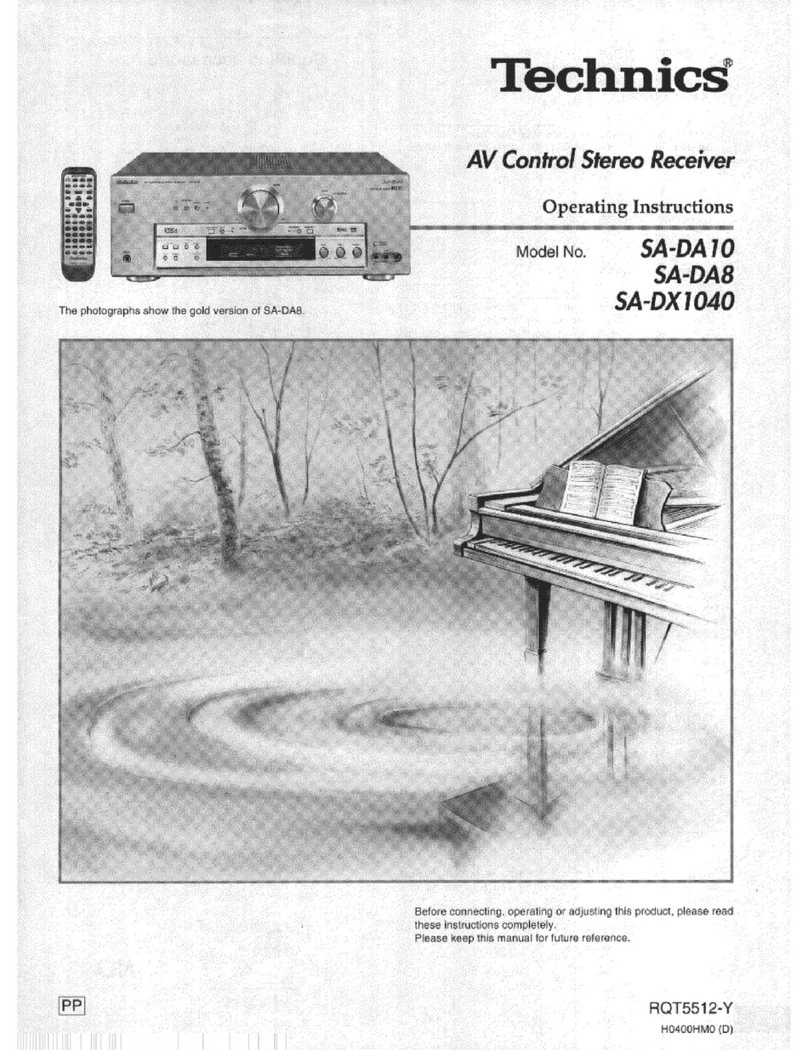
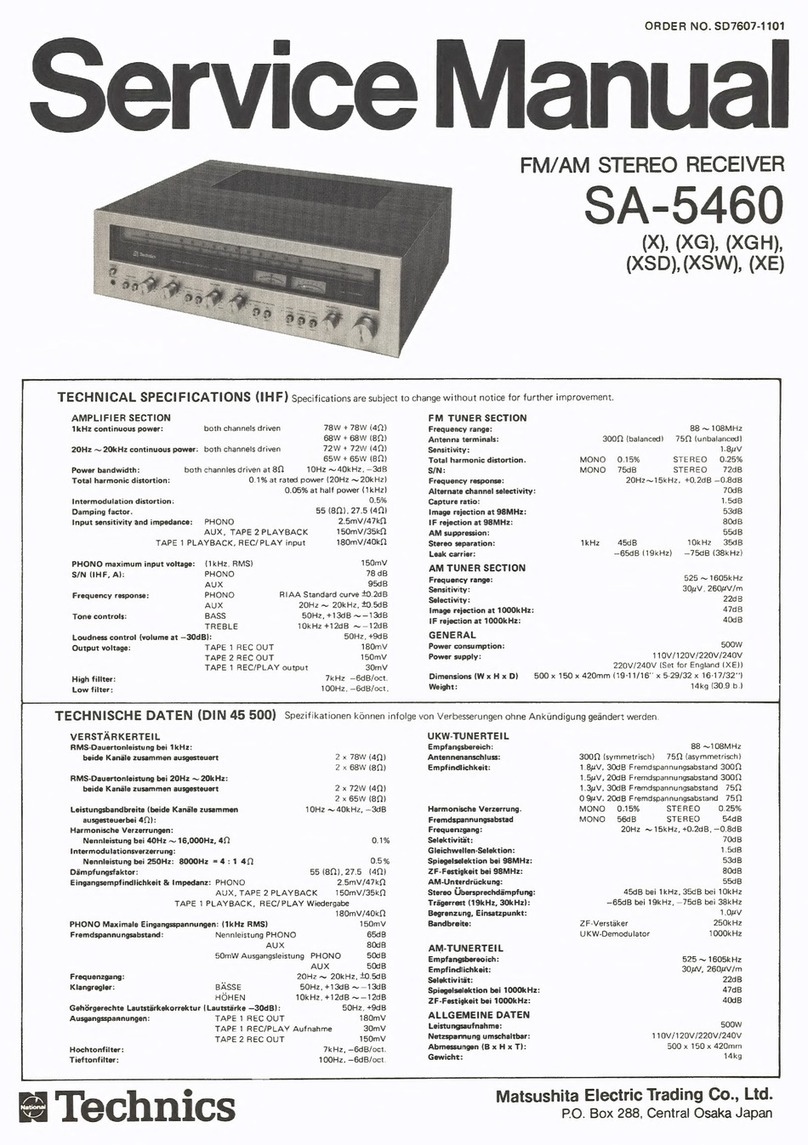
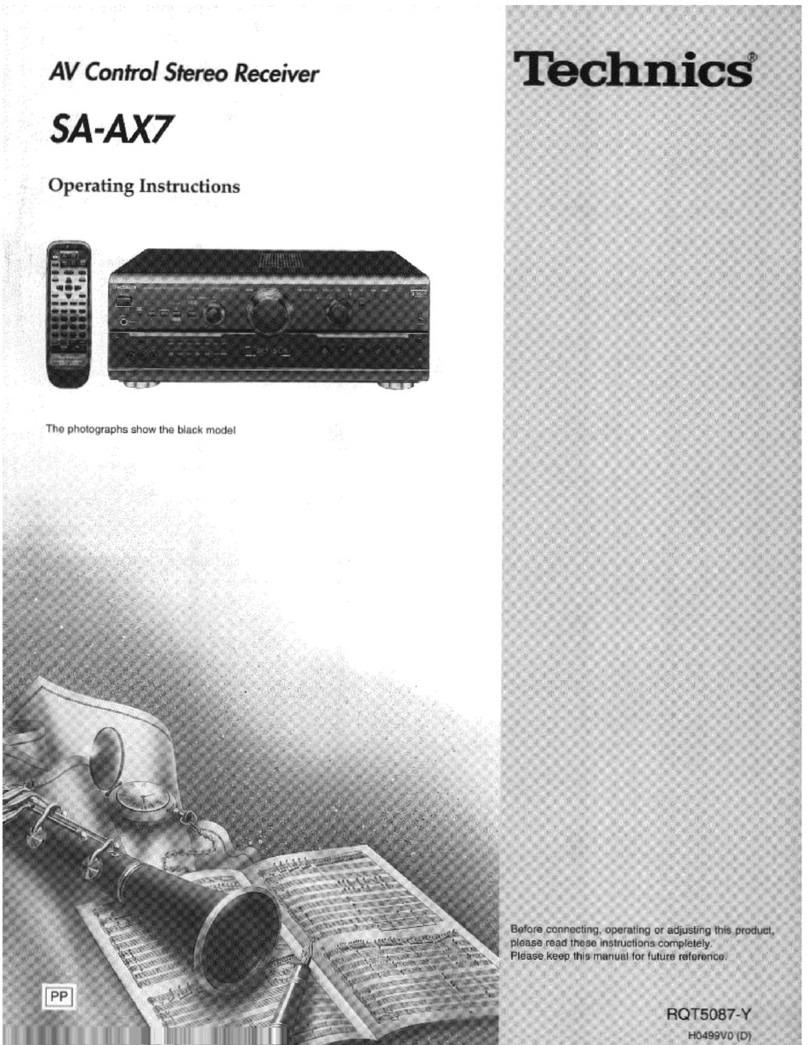
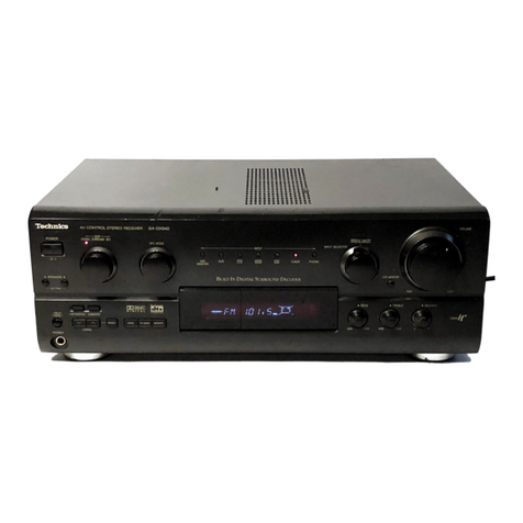
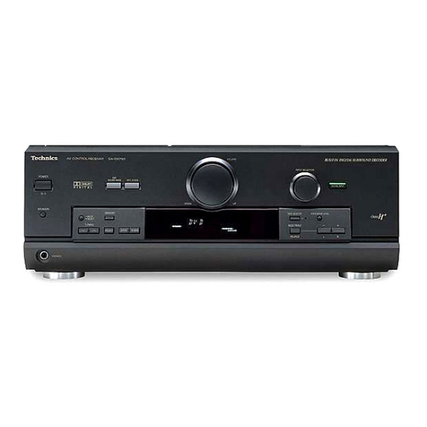
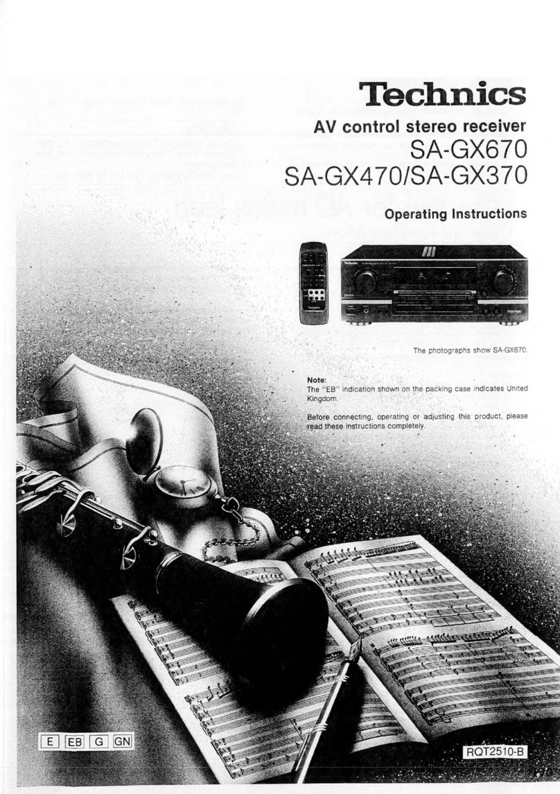
  9. Technics SA-AX730 User manual

Technics SA-AX730 User manual

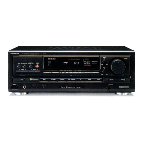
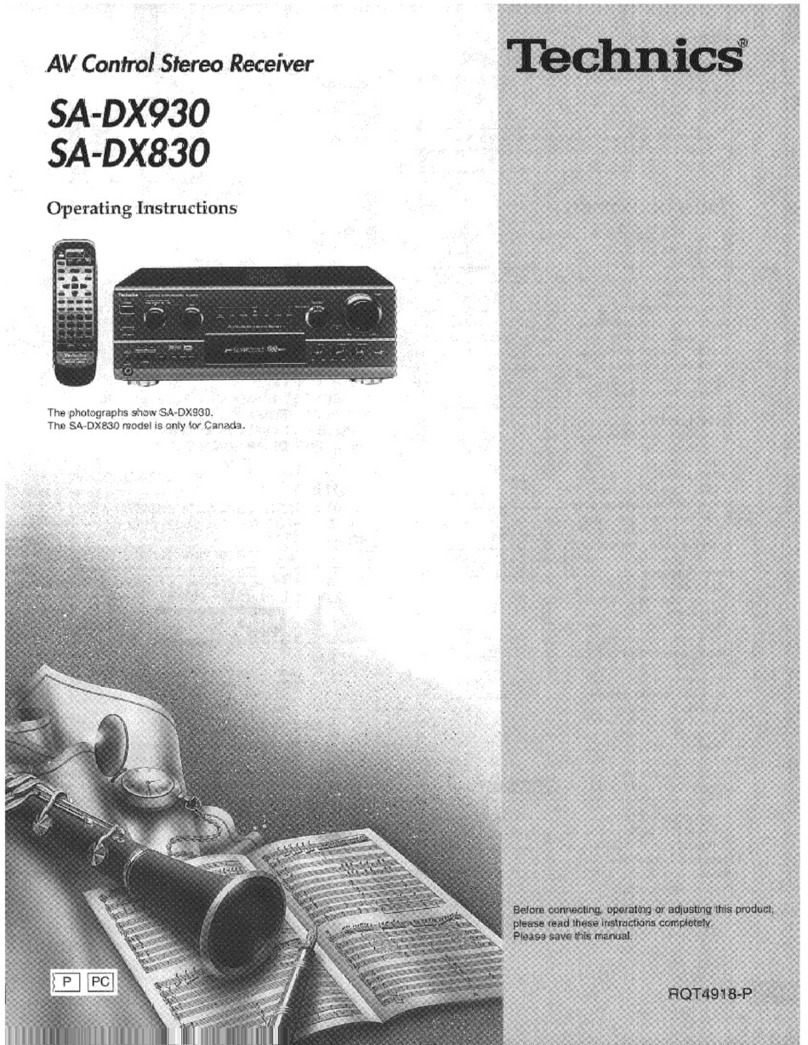
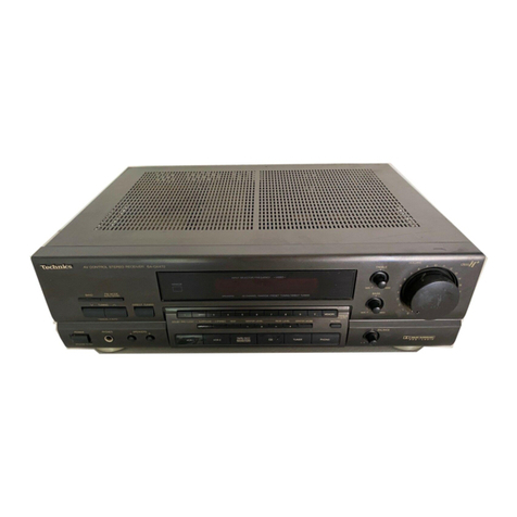
AV Control Stereo Receiver
SA-AX730
SA-AX530
Technics"
The photographs show SA-AX730.
Dear Customer
Thank you for purchasing this product.
For optimum performance and safety, please read these
instructions carefully.
These operating instructions are applicable to models
SA-AX730 and SA-AX530, however, are intended primarily
for model SA-AX730.
Table of contents
Precautions 3
Supplied accessories 4
Concerning the remote control 4
Surround guide 5
Front panel controls 6
Equipment connections 8
Antenna connections 12
Speaker connections 14
Basic operations 16
Listening to radio broadcasts 18
Sequential tuning 18
Direct tuning 19
Preset tuning 20
Dolby Pro Logic 22
Setting the center mode and adjusting speaker output level 22
Adjusting the delay time 24
Enjoying SURROUND or 3STEREO 25
SFC (Sound Field Control) 26
Adjusting field of sound 27
DVD 6CH INPUT mode 28
Other functions 29
To adjust the tone quality 29
To adjust the sound balance 29
To mute the sound level 29
To listen through headphones 29
Making arecording 30
Recording on atape deck 30
Recording on aVCR.... 30
Using the remote control 31
To operate the receiver 31
To operate acassette deck 32
To operate aCD changer or CD player 33
To watch TV broadcasts 34
To watch video tapes 35
To operate aDVD player 36
Changing the remote control code.
37
About the HELP function 38
Listening caution 38
Maintenance 38
Product Service 38
Troubleshooting guide 39
Technical specifications Back cover
SA-AX730 only
CAUTION
Do not place atape deck, CD, or DVD player on top of this unit.
Heat radiated from the top of this unit may cause damage to
the software.
NO
User memo:
DATE OF PURCHASE
DEALER NAME
DEALER ADDRESS
TELEPHONE NUMBER
The model number and serial number of this product can be
found on either the back or the bottom of the unit.
Please note them in the space provided below and keep for
future reference.
MODEL NUMBER
SERIAL NUMBER
-THE FOLLOWING APPLIES ONLY IN THE U.S.A.-
CAUTION:
Any unauthorized changes or modifications to this
equipment would void the user's authority to operate this
device.
WARNING:
TO REDUCE THE RISK OF FIRE, ELECTRIC
SHOCK OR PRODUCT DAMAGE, DO NOT
EXPOSE THIS APPLIANCE TO RAIN,
SPLASHING, DRIPPING OR MOISTURE.
CAUTION:
TO PREVENT ELECTRIC SHOCK MATCH WIDE
BLADE OF PLUG TO WIDE SLOT, FULLY
INSERT.
CAUTION: TO REDUCE THE RISK OF ELECTRIC
SHOCK, DO NOT REMOVE SCREWS.
NO USER-SERVICEABLE PARTS
INSIDE.
REFER SERVICING TO QUALIFIED
SERVICE PERSONNEL.
AThe lightning flash with arrowhead symbol, within
an equilateral triangle, is intended to alert the user
to the presence of uninsulatedMangerous voltage"
within the product's enclosure that may be of suffi-
cient magnitude to constitute arisk of electric shock
to persons.
The exclamation point within an equilateral triangle
is intended to alert the user to the presence of
important operating and maintenance (servicing)
instructions in the literature accompanying the ap-
pliance.
ROT4731
Precautions
Before using this unit please read these operating instructions
carefully. Take special care to follow the warnings indicated on the
unit itself as well as the safety suggestions listed below.
Afterwards keep them handy for future reference.
Safety
1. Power Source—The unit should be connected to power
supply only of the type described in the operating instructions
or as marked on the unit.
2. Polarization—If the unit is equipped with apolarized AC
power plug (a plug having one blade wider than the other), that
plug will fit into the AC outlet only one way. This is asafety
feature. If you are unable to insert the plug fully into the outlet,
try reversing the plug. If the plug should still fail to fit, contact
your electrician to replace your obsolete outlet. Do not defeat
the safety purpose of the polarized plug.
3. Power Cord Protection—AC power supply cords should be
routed so that they are not likely to be walked on or pinched by
items placed upon or against them. Never take hold of the plug
or cord if your hand is wet, and always grasp the plug body
when connecting or disconnecting it.
4. Nonuse Periods—When the unit is not used, turn the power
off. When left unused for along period of time, the unit should
be unplugged from the household AC outlet.
Installation
Environment
1. Outdoor Antenna Grounding—If an outside antenna is
connected to the receiver, be sure the antenna system is
grounded so as to provide some protection against voltage
surges and built-up static charges. Section 810 of the National
Electrical Code, ANSI/NFPA No. 70-1990, provides
information with respect to proper grounding of the mast and
supporting structure, grounding of the lead-in wire to an
antenna discharge unit, size of grounding conductors, location
of antenna-discharge unit, connection to grounding electrodes,
and requirements for the grounding electrode. See figure
below.
POWER SERVICE GROUNDING
ELECTRODE SYSTEM
(NEC ART 250, PART H)
Placement
1. Ventilation —The unit should be situated so that its location or
position does not interfere with its proper ventilation. Allow
10 cm (4") clearance from the rear of the unit.
2'. Foreign Material—Care should be taken so that objects do
not fall into and liquids are not spilled into the unit. Do not
subject this unit to excessive smoke, dust, mechanical
vibration, or shock.
3. Magnetism—The unit should be situated away from
equipment or devices that generate strong magnetic fields.
4. Stacking—Do not place heavy objects, other than system
components, on top of the unit.
5. Surface—Place the unit on aflat, level surface.
6. Carts and Stands—The unit should be used only with acart or
stand that is recommended by the ^0^^
manufacturer. The unit and cart combination M2k<P\%
should be moved with care. Quick stops, I£"Tww
excessive force, and uneven surfaces may ^BLafili
cause the unit and cart combination to
overturn.
7. Wall or Ceiling Mounting—The unit should not be mounted to
awall or ceiling, unless specified in this operating instructions.
Maintenance
Clean the cabinet, panel and controls with asoft cloth lightly
moistened with mild detergent solution.
Do not use any type of abrasive pad, scouring powder or solvent
such as alcohol or benzine.
Service
1. Damage Requiring Service—The unit should be serviced by
qualified service personnel when:
(a) The AC power supply cord or the plug has been damaged;
or
(b) Objects have fallen or liquid has been spilled into the unit;
or
(c) The unit has been exposed to rain; or
(d) The unit does not appear to operate normally or exhibits a
marked change in performance; or
(e) The unit has been dropped, or the enclosure damaged.
2. Servicing—The user should not attempt to service the unit
beyond that described in the operating instructions. All other
servicing should be referred to an authorized service
personnel.
For the address of an authorized servicenter:
In the U.S.A. 1-800-211-7262 or web site
(http://www.panasonic.com)
In Canada 905-624-5505 or web site
(www.panasonic.ca/fdbckca.htm)
NEC—NATIONAL ELECTRICAL CODE
2. Water and Moisture—Do not use this unit near water—for
example, near abathtub, washbowl, swimming pool, or the
like.
Damp basements should also be avoided.
3. Heat—The unit should be situated away from heat sources
such as radiators and the like.
It also should not be placed in temperatures less than 5*C
(41 "F) or greater than 35°C (95T).
{RJA0065-A)
(RSA0006)
(RSA0010)
e)
«)
®SA-AX730 |gA-AX930|
(EUR646496) (EUR646489)
Insert the batteries in the
correct polarities (©,©)-
®
(R6, AA, UM-3)
aRemote control signal sensor
Transmission
window
°oo
ocporm /\®© ®
Avoid any obstacles
About 7meters (23 feet) in
front of the signal sensor.
(The actual range will
depend on the angle at
which the remote control is
used.)
Supplied accessories
Please check and identify the
supplied accessories.
®AC power supply cord 1pc.
©AM loop antenna set
•AM loop antenna 1pc.
•AM loop antenna holder 1pc.
•Screw 1pc.
D©FM indoor antenna 1pc.
@Batteries 2pes.
Q ® Remote control transmitter 1pc.
Use numbers indicated in parentheses when asking for
replacement parts.
(Only for U.S.A.) .
To order accessories contact 1-800-332-5368 or web site
(http://www.panasonic.com).
Concerning the remote control
Battery installation
Use of batteries
•Do not mix old and new batteries, or batteries of different types
(manganese and alkaline, etc.).
•Never subject batteries to excessive heat or flame; do not
attempt to disassemble them; and be sure they are not short-
circuited.
•If the remote control is not to be used for along period of time,
remove the batteries and store them in acool, dark place.
•Do not attempt to recharge alkaline or carbon batteries.
•Do not use rechargeable type batteries.
Correct method of use
Operation notes
•Do not place obstacles between the remote control signal sensor
and remote control unit.
•Do not expose the remote control signal sensor to direct sunlight
or to the bright light of an invertor fluorescent light.
•Take care to keep the remote control signal sensor and end of
the remote control unit free from dust.
•If the unit is installed in arack with glass doors, the glass doors'
thickness or color might make it necessory to use the remote
control ashorter distance from the unit.
To prevent damage
•Never place heavy items on top of the unit.
•Do not disassemble or reconstruct the unit.
•Do not spill water or other liquids into the unit.
Surround guide
Software
You are able to enjoy these two surround systems with this receiver.
Surround system Features
SFC
(Sound Field
Control)
Dolby Pro Logic is adecoding system that was
developed to get abetter sense of presence from
sources encoded with Dolby Surround. The
feeling of position has been improved by the
addition of aseparate center speaker channel.
Dolby Surround was developed to allow
enjoyment of Dolby Stereo, acinema system, in
private homes. This system reproduces sound
close to that of the original movie through use of
an analog matrix.
This unit has two types of Dolby Pro Logic.
•SURROUND: the surround speakers are
used.
•3STEREO: the surround speakers are not
used.
(*Page22.) ^
r\
SFC allows you to add surround-like effects to
sources not formatted with Dolby Surround, Dolby
Digital, or DTS.
Various effects, like aconcert hall or jazz club,
can be achieved by introducing width or
reverberation to the original sound.
(*Page 26.)
•Video tapes
•Laser discs
•DVDs
•CDs
Software encoded with Dolby
Surround can be identified with this
mark.
[in !DOLBY SURROUND |
Any kind, but particularly music CDs
and video tapes.
3
CQ
DTS
Dolby Digital is adiscrete 6(5,1) channel digital
surround system developed for cinema use.
The sound signals in Dolby Digital format are
compressed to 1/10 their original size, allowing an
entire movie to be recorded on asingle DVD.
Not all Dolby Digital sources are recorded with 6
channels. Some sources marked Dolby Digital
may be recorded in Dolby Surround, a2channel
system.
(*Page 28.)
DTS is adiscrete 6(5.1) channel digital surround
system developed for cinema use. Sources
encoded in DTS are only compressed to aquarter
of the size of the original to preserve sound
quality.
DTS sources are produced with the intention that
all speaker channels will be used.
(*Page 28.)
•DVDs
Both the playback equipment and
software must have this mark.
|DOLBY i
DIGITAL
•DVDs
•Laser discs
•CDs
Both the playback equipment and
software must have this mark.
DIGITAL
SURROUND
5
RQT4731
Front panel controls
Main unit
No. Name Ref.page
©Power "6/1" switch
(POWER, 6/I) 16
Press to switch the unit from on to standby mode or vice versa.
In standby mode, the unit is still consuming asmall amount of
power.
©Sound mode selector/indicators 22
(D SFC mode selector (MODE) 26
®Input indicators 1
6
©DVD 6ch input select button/indicator
(DVD 6CH INPUT) 28
©Input selector (INPUT SELECTOR) 16
©Volume control (VOLUME) 16
Speaker select buttons (SPEAKERS A, B) 16
[SA-AX530l
Speaker button (SPEAKERS) 16
No. Name Ref.page
(D Help/reset button (-HELP -RESET) 38
®Headphones jack (PHONES) 29
©Display
©Tape monitor button (TAPE MONITOR) 17
©Bass control (BASS) 29
©Treble control (TREBLE) 29
©Balance control (BALANCE) 29
©Delay time adjust button (DELAY TIME) 24
©Center mode select button
(CENTER MODE) 22
©Tuning buttons (TUNING V,A) 18
©Radio station presetting button (PRESET) 21
©Band select button (BAND) 18
®FM mode select button (FM MODE) 18
@Memory button (MEMORY) 20
Front panel controls
Remote control
0>
(z>
CD
(5>
d> DISPLAY
IDELAY HVEL .
<0>
ooc
789
OOPo
>1£VENTER
_V CH AlTV/VIDEO
—
©
MUTING -VOL +
ooo ©
<2>
No. Name Ref.page
©Power button (6)31
<D button ()32
©km /«button {h< I
«
)32
®button ()32
©Title button (TITLE) 36
©Display button (DISPLAY) 36
©Dolby Pro Logic surround select button
(SURROUND) 31
©Dolby Pro Logic/SFC off button (STEREO) 31
©Speaker channel select button (LEVEL) 31
©Delay time button (DELAY) 31
©Channel up/down buttons (vCHa) 32
©Muting button (MUTING) 31
©Input select buttons
(TV, VCR, TAPE, CD, TUNER/BAND, DVD) 31
@button (»/»i) 32
©Cursor/select buttons 36
©Menu button (MENU) 36
©SFC mode select button (SFC) 31
©Test button (TEST) 23, 31
©Delay time/level adjust buttons (-, +) 23, 31
®Direct tuning/disc enter button
(DIRECT TUNING/DISC ENTER) 19, 32
@G3E333E!
>10/enter button (>10/ENTER) 32
[For SA-AX530I
>10 button (>10) 32
©Numeric buttons 19, 32
©Disc/deck 1/2 select button (DISC/DECK 1/2).. 32
@>TV/video select button (TV/VIDEO) 34
©Volume buttons (-VOL+) 23, 31
Q>
m
ROT4731
Equipment connections (SA-AX730)
Stereo connection cable (not included) Video connection cable (not included)
White (L) cQjQiiniv ^mnnff y=
Red (R) dm/tomS VnifflB^
Make sure that the power supply for all components has been
turned off before making any connections.
To connect equipment, refer to the appropriate operating
instructions.
Do not place books, etc., on the top of this unit or block the
heat radiation vents in any way.
Tapedeck (not included)
CD changer (or CD player)
(not included)
TV (not included)
II II
|tszzs
||[B 151
|
11|, 1n|II |"SWITCHED" AC outlet
Power to the outlet is controlled
by the power switch of this unit.
Audio equipment rated up to
TOTAL 80 Wcan be connected
here.
AC
Cooling fan
The cooling fan operates at
high power output levels
only.
AC power supply cord -
(included)
AC OUTLET
a
oHi 1°
^\'oB!BooS5|-^=-il
Connect this cord
only after all other
cables and cords are
connected.
Turntable (not included) VCR (not included)
Household AC outlet
(AC 120 V/60 Hz)
8
RQT4731
Monaural connection cable (not included)
<=\ it™
Optical fiber cable (not included)
Connecting aDVD player
6channel discrete connection enables you to enjoy the sound field effects recorded on DVDs.
SA-AX730
If your DVD player has surround decoders If your DVD player doesn't have surround decoders
Obtain aseparately available digital surround processor.
AUDIO OUT
(CENTER)
DVD player
(not included)
AUDIO OUT
(SUBWOOFER)
oo o
o
©o
© o
©c
©
AUDIO OUT
(SURROUND
L.R)
^2 ©
O
VIDEO
OUT
I?
AUDIO OUT
(FRONT L.R)
Digital surround
processor
AUDIO OUT 7......
(front l,r> (not included)
AUDIO OUT
(SURROUND
L.R)
—i
kDIGITAL
1
VIDEO OUT DIGITAL
OUT
DVD player
(not included)
o0rmW
o
o
Stereo connection
Use this connection if none of your equipment has a
surround decoder.
AUDIO OUT
(MIXED AUDIO OUT) r
O0ooo/ \
n-nV. J
o
VIDEO
OUT
0
©o
©
©Q©®
o
©o M-e—<CD&—
I
DVD player
(not included)
Equipment connections (SA-AX530)
Stereo connection cable (not included) Video connection cable (not included)
White (L)
Red (R)
Make sure that the power supply for all components has been
turned off before making any connections.
To connect equipment, refer to the appropriate operating
instructions.
Do not place books, etc., on the top of this unit or block the
heat radiation vents in any way.
Tape deck (not included)
CD changer (or CD player)
(not included)
TV (not included)
11 1 I
|rn—tn
]|io ai
|
1 1 1Inl 1MI-T"
"SWITCHED" AC outlet
Power to the outlet is controlled
by the power switch of this unit.
Audio equipment rated up to
TOTAL 80 Wcan be connected
here.
Turntable (not included) VCR (not included) Household AC outlet
(AC 120 V/60 Hz)
10
RQT4731
Monaural connection cable (not included) Optical fiber cable {not included)
«M „'JimnD (unnCO* °Cf01 :
Connecting aDVD player
6channel discrete connection enables you to enjoy the sound field effects recorded on DVDs.
SA-AX530
If your DVD player has surround decoders If your DVD player doesn't have surround decoders
Obtain a separately available digital surround processor.
DVD player
(not included)
AUDIO OUT
(SUBWOOFER)
AUDIO OUT
{FRONT L,R) n-n\^|
AUDIO OUT
(CENTER)
©oIo®,—
V£) DVD 6CH
SURWUNO SUAKUMO
©OiP_©J
©OO®^
©OOO"
AUDIO OUT
(SURROUND
L,R)
^llME'i
VIDEO
OUT
Digital surround
processor
AUDIO out .....
(Subwoofer) (not included)
DVD player
(not included)
Stereo connection
Use this connection if none of your equipment has a
surround decoder.
AUDIO OUT
(MIXED AUDIO OUT)
© o
© o
© o
©o
© o
ft
0
o
0irzrr1
VIDEO
OUT
(R) FHOKI (TJ
o®DVD/
"O ®1
OO-
DVD player
(not included)
FM indoor antenna
(not included)
Adhesive tape
AM loop antenna
(included)
AM ANT
AM LOOP ANT
Screw (included)
Antenna connections
FM indoor antenna (included)
This antenna is normally sufficient for reception of FM broadcasts.
Attach to awall (using tape) facing in the direction of best
reception.
For best reception
An FM outdoor antenna is recommended.
AM loop antenna (included)
This antenna is normally sufficient for reception of AM broadcasts.
Fit the AM loop antenna holder (included) onto the rear panel of
this unit and then attach the AM loop antenna to the AM loop
antenna holder (facing in the direction of best reception).
Pay attention to the following points when mounting the
antenna.
•Do not mount it close to power cords, speaker wires or metal
surfaces (Doing so will result in noise).
•Do not mount it close to atape deck. When the tape deck is
being used, chirping or beeping sounds may result.
When mounting the antenna to acolumn, awall or rackQ
Mount the antenna so that the hinge is vertical.
FM outdoor antenna
(not included)
75 Qcoaxial cable
(not included)
®Remove apiece of the
outer vinyl insulator.
20 mm (25/32")
>Twist the shield braid to
expose the core wire.
Core wire
Shield braid
10 mm (3/8")
C|) Connect the shield braid and the
core wire as shown at left.
Vinyl-covered wire
(not included)
Antenna connections
FM outdoor antenna (not included)
An outdoor antenna should be used when using this unit in
mountainous areas or in spaces enclosed by reinforced concrete
where the FM indoor antenna (included) does not provide
satisfactory reception.
Disconnect the FM indoor antenna if an FM outdoor antenna is
installed.
An outdoor antenna should be installed by a qualified technician
only.
AM outdoor antenna (not included)
An outdoor antenna should be used when using this unit in
mountainous areas or in spaces enclosed by reinforced concrete
where the AM loop antenna (included) does not provide
satisfactory reception.
Stretch 5-12 m(16-40 ft.) of vinyl-covered wire horizontally
across awindow frame or other convenient location, keeping it as
high as possible from the ground.
When the unit is not in use, disconnect the outdoor antenna to
prevent possible damage that may be caused by lightning. Never
use an outdoor antenna during an electrical storm.
Be sure to connect the AM loop antenna even when an outdoor
antenna is used.
AM ANT
AM LOOP ANT
AM loop antenna
(included)
_1
Speaker connections
Placement of speakers
Front speaker
(Left)
(not included)
Center speaker
(not included) Front speaker
(Right)
(not included)
Surround speaker
(Left)
(not included)
Subwoofer
(not included)
Surround speaker
(Right)
(not included)
Connecting speakers
Other connections are possible depending on your speaker system.
See your speaker system's operating instructions for details.
Front speakers
Place the front speakers on the left and right of the TV at seated
ear height so there is good coherency between the picture and
sound.
Center speaker
Place this speaker underneath or above the center of the TV. Aim
the speaker at the seating area.
Surround speakers
Place these speakers on the side of or slightly behind the listener,
and about one meter higher than ear level.
Subwoofer
The subwoofer can be placed in any position as long as it is at a
reasonable distance from the TV.
Note that some experimentation can yield the smoothest low
frequency performance. Placement near acorner can increase the
apparent output level, but can result in unnatural bass.
Front speakers
SA-AX530I This model has only one set of front speaker terminals.
Front speaker
Speaker impedance:
SA-AX730
ISA-AX530I
Aor B: 4-8 Q
Aand B: 8£1
8£1
(Right)
(not included)
Front speaker
(Left)
(not included)
"53
6)
(S
ET
O®
O©
O©
O©
'O©
®o©
Speaker cable
(not included)
:OUT
11
Connecting the cables SA-AX730 only
"B" terminals
For connection to asecond pair of speakers.
PBffS
Use the Aterminals to enjoy Dolby Pro Logic, SFC, and DVD 6CH
INPUT.
RQT4731
Other speakers
Surround speaker
(Right) (not included)
Surround speaker
(Left) (not included)
Center speaker
(not included)
Speaker cable
(not included)
Monaural-Stereo converter cable (not included)
(Connect to the Lor Rterminal if amonaural cable is used.)
Subwoofer without built-in
amplifier (not included)
For surround speakers
Do not connect the surround speakers to the front speaker
terminals. The surround speakers may be damaged if connected
to the front terminals.
For subwoofer
This receiver has no amplifier section designed especially for the
subwoofer.
For your reference
Connection to apassive subwoofer with front speaker terminals is
also possible. (See the operating instructions of the speaker
system for details.)
Speaker impedance:
Center speaker: 8n
Surround speaker: 8H
Basic operations
POWER
SA-AX730
ASPEAKERS B
ISA-AX530I
SPEAKERS
INPUT SELECTOR
VOLUME
VOLUME
SPEAKERS
aon)
///
///
Selected source
Before operation, set VOLUME to the "MIN" position.
Press [POWER].
SA-AX730
Press [A] and/or [B] to select the speaker
system(s) to be used.
Aand Brefer to the speaker terminals at the rear of the unit.
ISA-AX530I
Press [SPEAKERS] and check the
"SPEAKERS" indication lights up.
If the button is pressed once more, the indicator will switch
off and no sound will be heard from the speakers.
Turn [INPUT SELECTOR] to select and start
the desired source.
(Refer to the appropriate operating instructions for details.)
The indicator which corresponds to the selected input source
will illuminate.
The selected source will be shown on the display.
TAPE (MONITOR): To listen to cassette tapes
VCR: To watch video tapes
TV/DSS: To watch TV or DSS
DVD: To watch DVD
CD: To listen to compact discs
TUNER: To listen to radio broadcasts
PHONO: To listen to phono discs
If aDolby Pro Logic or SFC mode has been
selected
After displaying the selected source, the display will then
change to show the Dolby Pro Logic or SFC mode.
If the source chosen was TUNER then the display will
change again to show the frequency.
To watch avideo (or DVD) or the TV, set the TV to either the
TV mode or VIDEO mode.
For your reference
If you are using aVCR and you select TAPE, CD, TUNER,
or PHONO, the picture will remain on the screen.
il Adjust the volume.
When you finish listening
Be sure to reduce the volume level, and switch the power to the
standby condition by pressing [POWER].
Basic operations
ASPEAKERS 6
3ASPEAKERS B
When using speakers under 8QpgfiPi>:wcitf!Bffl Q
Press and hold [A] or [B] until "LOW IMP" lights
up on the display.
If even one of the speakers being used has an impedance under
8Q, press and hold down either button Aor button Bfor 4
seconds or more to set the impedance to LOW.
(Press and hold down once again for 4seconds or more to turn it
off.)
Note that when "LOW IMP" is illuminated, speakers and ID
cannot both be used at the same time.
To change aspeaker:
e.g. To use speaker HI, press [A] (Q goes out), and then press
[B] to activate speaker ID-
Tape monitor EJ
If [TAPE MONITOR] is pressed while asource other than
'"TAPE (MONITOR)" is selected, the "TAPE (MONITOR)" indicator
lights and the tape monitor comes on.
Sources other than tape can still be selected with
[INPUT SELECTOR] while the "TAPE (MONITOR)" indicator is on.
Press [TAPE MONITOR] again to turn the tape monitor off.
(^ See "Recording" on page 30 for details on how to use the tape
monitor during recording.)
Listening to radio broadcasts
FM MODE
INPUT SELECTOR
/IIl\ 11_ /_/
I I 1 1Vi I I
BAND /_ fl/7
/ / /
/_/ //_/
III. I
Selected band
VA
TUNING
/_ n/i
I I I
l_l l_l
int.
Sequential tuning
Use the tuning buttons to tune-in radio stations.
Turn [INPUT SELECTOR] to select "TUNER".
Press [BAND] to select "FM" or "AM".
Press [TUNING (V)or (A)] to tune to the
desired frequency.
"QUARTZ LOCK" lights up when tuned.
"STEREO" lights up when an FM stereo broadcast is
received.
To make an automatic search for stations
If [TUNING (V) or (A)] is held down for an instant until the
frequency begins to scroll, the broadcast stations are tuned
in automatically when one is found.
Tuning may stop automatically if any jamming is
encountered.
If noise is excessive in the FM stereo mode
Press [FM MODE].
("STEREO" will go out, and "MONO" will light up)
The broadcast will be monaural, but noise will be reduced.
If the button is pressed once more, the stereo mode resumes.
For your reference
The tuner can pick up interference from DVD players. If this
occurs turn the DVD off.
Listening to radio broadcasts
Direct tuning
by remote control only
O
o<±> o
oQ o
tap™0
ft oa
CfO'cTcJ
w
Selected band
DIRECT TUNING/
DISC ENTER fl/l
/ /
ooo
666
6666
QUARTZ LOCK
STEREO /1/7
/ / "''til
III I. I
Specify the frequency using the numeric buttons on the remote
control to directly tune to the desired station.
Press [TUNER/BAND].
This will set the remote control to operate the tuner.
The selector on the receiver will change to "TUNER".
Each time the button is pressed, the band will change as
follows,
FM AM.
Press [DIRECT TUNING/DISC ENTER].
While cursor display is flashing (approx. 10 seconds)
Press the numeric buttons to enter the
frequency.
If the desired FM frequency is 107.9 MHz, press !
EMEl->[2]-»[Il. I
If the frequency has been input correctly, the displayed
frequency will blink once. \
E39
If no button is pressed while the cursor display is flashing,
the display will return to the frequency which is currently
being received. To re-specify the frequency, repeat the
procedure from step 2.
If the frequency has not been input correctly, "ERROR"
will be displayed. In this case, re-enter the frequency.
RQT4731
Listening to radio broadcasts
Preset tuning
Presetting radio stations into the memory channels of this unit
makes selecting stations simple.
Atotal of 30 FM and AM stations can be preset.
Please remember this
If anew broadcast station is preset into achannel, the setting for
the broadcast station which was previously entered in that channel
will be automatically erased.
Automatic memory presetting
Automatic memory presetting allows this unit to automatically
search for broadcast stations and then preset them into memory.
With this method, the channels that can be preset into the memory
are set as follows for different bands (FM or AM).
When FM stations are preset,
For FM stations 1-30
When FM and AM stations are preset,
For FM stations 1-20
For AM stations 21-30
HSet to the frequency from which you want to
start automatic memory presetting.
(^Page 18-19.)
BPress [MEMORY] until the frequency begins
to change.
(Automatic memory presetting will start.)
During automatic memory presetting, the memory indicator
will flash while the frequency scrolls.
To stop, press [MEMORY] once again.
When abroadcast station is preset El
The memory indicator and the preset channel number will be
displayed for approximately 1second.
When presetting is completed
The last broadcast station to be preset will be displayed.
Frequencies may not be preset correctly in cases where the
broadcast waves are too strong or too weak. In such cases, carry
out presetting manually. (^ Page 21.)

Other manuals for SA-AX730

1

This manual suits for next models

1

Other Technics Stereo Receiver manuals

Technics SA-110 User manual

Technics

Technics SA-110 User manual

Technics SADX930 - RECEIVER User manual

Technics

Technics SADX930 - RECEIVER User manual

Technics SAEX140 - RECEIVER User manual

Technics

Technics SAEX140 - RECEIVER User manual

Technics SH-AC500D User manual

Technics

Technics SH-AC500D User manual

Technics SA-EX510; SA-EX410; SA-EX310 User manual

Technics

Technics SA-EX510; SA-EX410; SA-EX310 User manual

Technics SA-5250 User manual

Technics

Technics SA-5250 User manual

Technics SA-500 (DG) User manual

Technics

Technics SA-500 (DG) User manual

Technics SA-GX100L User manual

Technics

Technics SA-GX100L User manual

Technics SA-GX130D User manual

Technics

Technics SA-GX130D User manual

Technics SA-GX550 User manual

Technics

Technics SA-GX550 User manual

Technics SA-GX910 User manual

Technics

Technics SA-GX910 User manual

Technics SA-DX940 User manual

Technics

Technics SA-DX940 User manual

Technics SA-5570 User manual

Technics

Technics SA-5570 User manual

Technics SA-EX100 User manual

Technics

Technics SA-EX100 User manual

Technics SA-GX530 User manual

Technics

Technics SA-GX530 User manual

Technics RQT5110-P User manual

Technics

Technics RQT5110-P User manual

Technics SA-DX750 User manual

Technics

Technics SA-DX750 User manual

Technics QUARTZ SA-R330 User manual

Technics

Technics QUARTZ SA-R330 User manual

Technics SA-EX100 User manual

Technics

Technics SA-EX100 User manual

Technics SA-EX320 User manual

Technics

Technics SA-EX320 User manual

Technics SA-GX190 User manual

Technics

Technics SA-GX190 User manual

Technics RQT5087-Y User manual

Technics

Technics RQT5087-Y User manual

Technics SU-CH700 User manual

Technics

Technics SU-CH700 User manual

Technics SA-EX100 User manual

Technics

Technics SA-EX100 User manual

Popular Stereo Receiver manuals by other brands

Teleton CS-400 Service manual

Teleton

Teleton CS-400 Service manual

Bose SoundTouch Service manual

Bose

Bose SoundTouch Service manual

Marantz NR1710 quick start guide

Marantz

Marantz NR1710 quick start guide

Aiwa CX-NDP25 Service manual

Aiwa

Aiwa CX-NDP25 Service manual

Flaircomm Technologies BlueTone BTAV101 user manual

Flaircomm Technologies

Flaircomm Technologies BlueTone BTAV101 user manual

Roberts PlayDuo user guide

Roberts

Roberts PlayDuo user guide

Sony CFD-V6 Service manual

Sony

Sony CFD-V6 Service manual

Pioneer AVH-X390BT installation manual

Pioneer

Pioneer AVH-X390BT installation manual

AudioSource CD Ceiver One owner's manual

AudioSource

AudioSource CD Ceiver One owner's manual

Harman Kardon HK 3470 owner's manual

Harman Kardon

Harman Kardon HK 3470 owner's manual

Pioneer Elite VSX-LX102 Basic Manual

Pioneer

Pioneer Elite VSX-LX102 Basic Manual

Bose LIFESTYLE 550 Service manual

Bose

Bose LIFESTYLE 550 Service manual

Kenwood KR-4140 Service manual

Kenwood

Kenwood KR-4140 Service manual

Jensen CDX3119 Installation & owner's manual

Jensen

Jensen CDX3119 Installation & owner's manual

Aiwa Z-VR55 Service manual

Aiwa

Aiwa Z-VR55 Service manual

Aiwa AV-X220 operating instructions

Aiwa

Aiwa AV-X220 operating instructions

Lafayette LR-120DB OPERATING & SERVICE MANUAL

Lafayette

Lafayette LR-120DB OPERATING & SERVICE MANUAL

Panasonic SA-DT310E Service manual

Panasonic

Panasonic SA-DT310E Service manual

manuals.online logo
manuals.online logoBrands
  • About & Mission
  • Contact us
  • Privacy Policy
  • Terms and Conditions

Copyright 2025 Manuals.Online. All Rights Reserved.