Technifor TD412 User manual

www.technifor.com
Gravotech reserves all rights to modify its products.
This document is non contractual.
OPERATING AND MAINTENANCE MANUAL
INTEGRATION
TD412
MARKING LASER
integrable version
Ref. DCD01/3078 - TD412_en_C - Last updated: 01/2014

Ref. DCD01/3078 - TD412_en_C 2/62
Table of contents
A - Introduction ....................................................................................................................4
1. General Instructions ...............................................................................................................................4
Laser safety .......................................................................................................................................4
Marking head ....................................................................................................................................4
Control Unit .......................................................................................................................................4
2. Identification of the marking equipment ..................................................................................................5
3. Labels .....................................................................................................................................................5
Required safety labels .......................................................................................................................5
Warranty labels .................................................................................................................................5
Focal lens distance indications .........................................................................................................5
4. Regulation observance ...........................................................................................................................6
Declaration of incorporation ..............................................................................................................6
Declaration of compliance CE ...........................................................................................................6
B - Laser safety ...................................................................................................................8
1. Recommendations and safety regarding laser devices ..........................................................................8
Personnel safety ...............................................................................................................................8
Recommendations ............................................................................................................................8
2. Work station safety .................................................................................................................................9
General Instructions ........................................................................................................................10
Wearing safety glasses ...................................................................................................................10
3. Potential hazards related to materials worked with ..............................................................................11
Fumes and toxic particles ...............................................................................................................11
Examples of secondary radiation risks ............................................................................................11
C - Operating instructions for the machine ........................................................................12
1. Unpacking ............................................................................................................................................12
2. Description of the machine ...................................................................................................................14
3. Technical specifications .......................................................................................................................15
Laser beam .....................................................................................................................................15
Power supply ...................................................................................................................................15
Environment ....................................................................................................................................15
Aiming diode - focusing diode .........................................................................................................15
4. Physical characteristics ........................................................................................................................15
5. Dimensional drawings ..........................................................................................................................16
TD412 dimensional drawing ............................................................................................................16
Dimensional drawing of the Control Unit in rack configuration - standard version ..........................17
Dimensional drawing: Protective ring ..............................................................................................18
6. List of accessories available upon request ...........................................................................................19
Head accessories ............................................................................................................................19
Control Unit options and accessories ..............................................................................................21
D - Installation ...................................................................................................................22
1. Installation ............................................................................................................................................22
Mounting .........................................................................................................................................22
Possible integration and operating positions for the TD412 ............................................................23
2. Marking area ........................................................................................................................................24
3. Height adjustment ................................................................................................................................24
4. Connections .........................................................................................................................................25
Connection of the optical fiber .........................................................................................................27
Connection of the marking head to the CCU ..................................................................................28
RS232 connection for communication with PC ...............................................................................29
Connection to DB37F connector .....................................................................................................29
Connecting the RF cord for module/CCU connection .....................................................................29
Power supply connection ................................................................................................................29
5. Laser startup ........................................................................................................................................30
Starting up the laser when the CCU is integrated in a Class 1 safety chamber ..............................31

Ref. DCD01/3078 - TD412_en_C 3/62
6. Using the screen and function keys .....................................................................................................32
Main menu ......................................................................................................................................32
Internal mode / external mode ........................................................................................................32
Switching between internal/external mode ......................................................................................32
Adjusting the power from the CCU ..................................................................................................32
Contrast ...........................................................................................................................................33
"System info" menu .........................................................................................................................33
7. Laser shutdown ....................................................................................................................................34
Standby/Shutter operation ..............................................................................................................34
Cutting off the source ......................................................................................................................34
Power down ....................................................................................................................................34
Emergency stop ..............................................................................................................................34
E - Communication ............................................................................................................35
1. Dedicated Inputs/Outputs .....................................................................................................................35
Connection to DB37F connector .....................................................................................................35
Description of Inputs .......................................................................................................................37
Description of Outputs .....................................................................................................................39
Minimum cabling required ...............................................................................................................41
Timing diagrams of the communication signals ..............................................................................41
2. Generic Inputs/Outputs ........................................................................................................................44
Connection of the I/O Phoenix connector .......................................................................................44
Characteristics of the Inputs ............................................................................................................45
Characteristics of the Outputs .........................................................................................................45
3. Wiring example .....................................................................................................................................46
F - Marking ........................................................................................................................49
1. Marking process flowchart ....................................................................................................................49
2. Using the T700W program ...................................................................................................................50
G - Preventive maintenance .............................................................................................. 51
1. Optics maintenance ..............................................................................................................................51
Dust protection caps .......................................................................................................................51
Marking head ..................................................................................................................................51
2. Element ventilation and cooling ............................................................................................................52
H - Incidents and resolution of the problems ..................................................................... 53
1. Changing the fuse ................................................................................................................................53
2. Resolution of the problems ...................................................................................................................53
Error message management ...........................................................................................................53
Error message history .....................................................................................................................54
Summary table of the error codes ...................................................................................................55
Resolution of the problems .............................................................................................................56
I - Dismantling the system ................................................................................................. 58
J - Wearing and spare parts ..............................................................................................60
1. Spare parts ...........................................................................................................................................60
K - Noise emission of the machine .................................................................................... 61
1. Test code ..............................................................................................................................................61
Measurement method .....................................................................................................................61
Definition of the microphone position ..............................................................................................61
Test conditions ................................................................................................................................61
2. Noise emission information ..................................................................................................................61
L - Appendix ......................................................................................................................62

A
Ref. DCD01/3078 - TD412_en_C 4/62
AIntroduction
Technifor is a used, pending and/or registered trademark belonging to
Gravotech Group or one of its subsidiaries.
Thank you for choosing TD412 Technifor.
For more information on products, visit www.technifor.com website.
To ensure security and productivity, read this manual before starting-up the
equipment.
For help, contact Gravotech (see contact list, last page).
1. General Instructions
Laser safety
• Class 4 laser device designed for integration - See declaration of compliance.
• Observe norm EN 60825-1 concerning the controls and signage (access panels, doors, emergency stops...).
• Operators and service personnel must receive laser safety training. Carefully read the "Laser Safety" chapter.
For help, contact Gravotech (see contact list, last page).
• It is mandatory that the operator wear eye protection with the suitable filter lenses (DIR L6, 1064 nm - standard
EN207: 2010).
Marking head
• The optical fiber is not disconnectable on the marking head side, only on the CCU side.
• Electronic dimensional drawings available upon request
• The optical fiber, linking the CCU to the marking head, must respect a minimum bending radius of 90 mm
(3.543 in).
• Minimize shocks and vibrations on the marking head.
• The optical fiber must be connected before the Laser is started up (CCU side).
• Never ship the CCU connected to the marking head.
• Allow approximately ± 15 mm (0.591 in) for the focal point adjustment (list of accessories available upon
request: contact us).
• If the equipment is stored at a temperature inferior to 10 0C (50 0F) or superior to 35 0C (95 0F), leave it 24h at
a temperature between 15 0C (59 0F) and 35 0C (95 0F) before start-up.
Control Unit
• After unpacking the CCU, connect the optical fiber to the laser diode without delay (CCU side).
• In difficult environments (i.e.: oily mist, small dust particles, high humidity, high temperature...), place the CCU in
a filtered or even air-conditioned cabinet to protect it from damage.
• Allow clearance (connections and cables): analyse the CCU’s integration in order to avoid problems due to the
fiber’s minimum bend radius.
• Use a cooling system in a high temperature environment.
• In the event of power problems, install a UPS (power conditioner).
www.gravotech.com
AIntroduction A
Ref. DCD01/3078 - TD412_en_C 5/62
2. Identification of the marking equipment
The marking equipment is identified by:
• 1 identification plate on the marking head
• 1 identification plate on the Control Unit
• 1 identification plate on the Laser module
Have the model and serial number of the equipment available when contacting Gravotech.
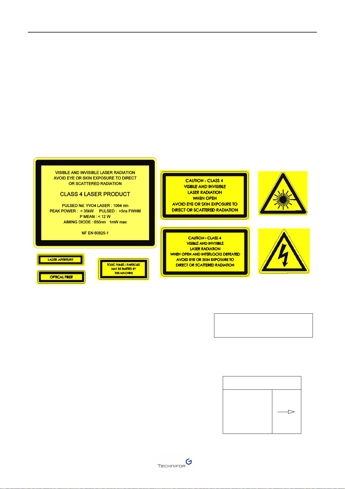
3. Labels
The various compliance labels are:
Required safety labels
Warranty labels
These labels guarantee the TD412 laser was not opened
or dismantled.
Opening without prior written consent voids warranty.
Focal lens distance indications
This label is placed on the marking head to indicate the distance to the
part.
These values are approximative.
DO NOT OPEN LASER COVER
WARRANTY VOID IF
SEAL IS BROKEN
LENS F(mm)
f 100 115
f 160 195
f 254 350
f 330 430

AIntroduction A
Ref. DCD01/3078 - TD412_en_C 6/62
4. Regulation observance
Declaration of incorporation
Manufacturer, GravoTech Marking SAS - 466 rue des Mercières - 69140 Rillieux-la-Pape - France (head office)
declares that the following equipment:
- description: marking machine
- model: TD412 + UCTD412
is compliant with the major requirements of Directive 2006/42/EC and in agreement with the clauses of article 4
paragraph 2 and annex II point B of the above-mentioned directive. This equipment must not be put into service
until the machinery into which it is to be incorporated has been declared completely compliant with all the
requirements of the Directive 2006/42/EC.
Declaration of compliance
Manufacturer, GravoTech Marking SAS - 466 rue des Mercières - 69140 Rillieux-la-Pape - France (head office)
declares that the following equipment:
- description: marking machine
- model: TD412 + UCTD412
is compliant with the following European directives and harmonised standards:
European directives that require a CE marking
• Directive 2006/95/EC of the European Parliament and of the Council of 12 December 2006 on the harmonisa-
tion of the laws of the Member States relating to electrical equipment designed for use within certain voltage
limits.
• Directive 2004/108/EC of the European Parliament and of the Council of 15 December 2004 on the harmonisa-
tion of the laws of the Member States relating to electromagnetic compatibility.
In this context, the equipment is compliant with the following norms:
- Standard NF EN 61000-6-2 of January 2006 concerning electromagnetic compatibility (EMC) - Part 6-2:
generic standards- Immunity for industrial environments.
- Standard NF EN 61000-6-4 of March 2007 concerning electromagnetic compatibility (EMC) - Part 6-4: generic
standards- Standard on emissions for industrial environments.
• Directive 2011/65/EU of the European Parliament and of the Council of 8 June 2011 restricting the use of some
dangerous substances present in electrical and electronical equipment (RoHS).
Other European directives
Equipment is compliant with the following European directives:
• amended Directive 2002/96/EC of the European Parliament and of the Council of 27 January 2003 on waste
electrical and electronic equipment (WEEE).
This symbol indicates that once this equipment has reached the end of its useful life, it must not be
disposed of with non-sorted municipal waste, in accordance with European Directive 2002/96/EC.
The equipment must be disposed of at an appropriate collection point for processing, sorting, and
recycling of Waste Electronic and Electrical Equipment (WEEE).
The elements which compose Waste Electronic and Electrical Equipment (WEEE) may contain substances which
have harmful effects on the environment or on human health.
By following these instructions, you are helping the environment, contributing to the preservation of our natural
resources, and protecting human health.

AIntroduction A
Ref. DCD01/3078 - TD412_en_C 7/62
Harmonised standards
Equipment including a laser is compliant with, among others, the following standard(s):
• Standard NF EN 60825-1: 2008 concerning safety of laser products - Part 1: equipment classification and requi-
rements.
To obtain complete list of standards to which we are compliant, please contact Gravotech.
The modification or transformation of this equipment, adaptation and installation of
accessories not recommended by Gravotech, integration, piloting by a command
device, connection to an external peripheral, modify this equipment’s characteristics
and therefore void the compliance with the applicable EU directives. Such
modifications would release and hold Gravotech harmless against any and all liability.
In this case, the machine and equipment installer is responsible for the final work
station’s compliance.
B
Ref. DCD01/3078 - TD412_en_C 8/62
BLaser safety
1. Recommendations and safety regarding laser devices
Personnel safety
Recommendations
• The marking head and the Control Unit must be clean and protected from dust. Exterior optics must be verified
and cleaned if necessary.
• Position the Control Unit horizontally, in a dry, ventilated area, at least 20 cm (7.874 in) from the floor (Recom-
mendations for integration)
• Use the appropriate protection when equipment is used in a polluted environment. Use of these protections are
the user’s or the integrator’s responsibility.
• Never unplug a cable while the Control Unit is turned on.
• Grounding must be done according to the regulations in effect to ensure the safety of the personnel. The con-
nection to the single phase power supply is made with a standard, 3 pin plug with grounding. It must be equip-
ped with an adequately calibrated 30 mA differential cut-off and protection device.
• Do not use this marking equipment in an explosive environment.
Gravotech will not be held responsible for injuries resulting from disregard for the above operating instructions or
other general safety rules applicable to the use of this equipment or resulting from misuse. Furthermore, disregard
for the instructions will void the warranty.
This machine is equipped with a class 4 laser source. This laser can produce
dangerous diffuse reflections. It may lead to skin and eye injuries as well as a fire risk.
Its use requires extreme caution.
Laser radiation is invisible, but exposure,direct or scattered, is hazardous toskin and
eyes.
It is mandatory that the operator wear eye protection with the suitable filter lenses.
The area in which the machine is used must be limited to authorized and protected
personnel only.
The operator is not to wear reflective objects on his/her arms/hands (i.e.: jewellery).
Marking reflective materials (those with a copper, gold or silver base)or materials with
a polished surface represents a hazard both for the operator and the machine.
No inflammable material is to be close to the reflected beam (i.e.: operator’s shirt,
curtains, wall covering in non-synthetic material: fire hazard).
Only Gravotech personnel, or persons authorized by Gravotech may service the
elements that constitute the marking machine. Any intervention by unauthorized third
party would exclude Gravotech’s liability.

ALaser safety B
Ref. DCD01/3078 - TD412_en_C 9/62
2. Work station safety
Concerned industrial use installation:
Use:
Installation:
Restricted area
The room in which this sign is posted is defined as a restricted laser area:
• in normal production phase (1)
• maintenance and setting phase (1)
• ..........................................................................(1)
Regulation in the restricted area
Access to the restricted laser area is regulated. Only competent personnel having attended proper training can
remain during the operation: this implies medical aptitude and laser safety training.
Any person authorized access to the restricted area is to observe the rules provided by the employer.
(1) To be filled in or crossed out.
Specific hygiene and safety instructions
_________________________________________
Personnel laser radiation protection
ALaser safety B
Ref. DCD01/3078 - TD412_en_C 10/62
General Instructions
Wearing safety glasses
Safety goggles and appropriate clothing providing efficient protection against laser radiation and its effects are
mandatory whenever in an area where laser radiation emission exceeds or equals class 3B AEL (accessible
emission limit).
As a user, it is mandatory to declare the use of class 4 laser station to current authorities and to follow their safety
recommendations.
• Avoid any exposure to laser radiation.
• Do not put hands or an object in the laser beam’s trajectory.
• Never stare into the primary laser beam.
• Avoid direct eye exposure to diode laser beam.
• Do not direct the beam towards other persons, openings or windows.
• Do not remove protection hoods or short-circuit the securities.
• Electrical interventions on the system can only be carried out by competent LT/HT
personnel.
• In the event of an incident or even doubts concerning the functioning of the instal-
lation, inform the person in charge of laser safety.
Name and address of the doctor in charge of medical exams for personnel occupying the laser restricted area:
.................................................................................. Tel: .....................................................................
Name and address of person in charge of the observance of laser security regulation in the restricted area:
.................................................................................. Tel: .....................................................................

ALaser safety B
Ref. DCD01/3078 - TD412_en_C 11/62
3. Potential hazards related to materials worked with
Fumes and toxic particles
The processing of parts using this type of Laser causes thermal and photo-electric (molecular) deterioration of the
material. Even micro-quantities of the by-product (soot or fumes), created during Laser marking, may accumulate
over a long period. Some of these by-products may prove to be hazardous to humans.
Health side-effects to the operators may include poisoning, allergies or cancer.
Here are some examples of the most sensitive materials:
• plastics and rubber
• painted materials
• anodized and galvanized metals
• ceramics
• materials containing lead or mercury
For a more detailed list of the risks related to the material worked with, consult Annex A of the ISO 11553-1:2005
norm.
In this case, adapt an extraction system (with filtration if necessary) to the marking station. This system vacuums
eventual emissions from the marking area.
It must be linked to:
• either a centralised vacuum system with an external evacuation.
• either an independent system dedicated to the marking station, which removes fumes and particles using
activated carbon filters.
The user must observe national legislation in force concerning chemical agent exposure limits.
For more information, contact us.
Examples of secondary radiation risks
The use of a class 4 laser device can generate:
• a risk of fire or explosion due to materials or inflammable substances
• UV radiation
•Xrays
• high intensity visible light when marking on certain materials
Laser marking certain materials emits dangerous fumes and particles that may be
toxic and/or damage the equipment.
In this case, adapt an extraction system (with filtration if necessary) to the marking
station.

C
Ref. DCD01/3078 - TD412_en_C 12/62
COperating instructions for the machine
1. Unpacking
Box 1
• main components:
- 1 technical document on CD ROM
- marking program
- 1 test plate for the machine
- a pair of safety goggles
- head/CCU connecting cable (x3)
- RS232 cable
- power cable
- DB37 connector with jumpers
- 2 caps for the focal lens’ protection
- additional accessories if ordered
Check the optical fiber was not damaged during transport.
1 : Laser module + marking head + optical fiber (not disconnectable)

AOperating instructions for the machine C
Ref. DCD01/3078 - TD412_en_C 13/62
Box 2
• Control Unit
Remove the CCU’s protective packing at the last moment. Quickly connect the optical
fiber as soon as the marking head is in position on its mounting bracket (workstation).
Remove the protective plugs only when installing.
Unpack as shown in the following diagram.
Keep the packing in case the machine has to be returned.
Dismantling the system: see page(s) 58

AOperating instructions for the machine C
Ref. DCD01/3078 - TD412_en_C 14/62
2. Description of the machine
The TD412 consists of a module/marking head assembly and a Control Unit which together constitute a class 4
Laser source.
The CCU contains all the electronic elements required for the equipment to function (power, control and
command).
Never ship the CCU connected to the marking head.
Marking is carried out by the marking head, which integrates two motors (X- Y) to displace the laser beam on the
part to mark.
1 : Green light - Shutter’s condition
2 : Red light - Laser radiation
3 : Focal lens (depending on selected option)
4 : Head attachment
5 : Connector CCU/head (x2)
6 : Laser module (optical components)
7 : Element ventilation and cooling
8 : RF cord for module/CCU connection
9 : Optical fiber
Marking head
Control Unit

AOperating instructions for the machine C
Ref. DCD01/3078 - TD412_en_C 15/62
3. Technical specifications
Laser beam
• class 4 (EN60825-1) (class 1 with suitable protection)
• power: 12 W maximum
• minimim pulse duration: 5 ns
• frequency: 5 kHz - 200 kHz
• wave length: 1064 nm
Power supply
• power supply: 100 - 240 V AC - 50/60 Hz - 400 W (700 W max)
• phases: 1
• fuse: 3.15 A - 230 V / 6.3 A - 115 V
Environment
• operating temperature: 15 0C (59 0F) - 35 0C (95 0F)
• storage: 10 0C (50 0F) - 40 0C (104 0F)
• humidity level: 20 - 80%
Aiming diode - focusing diode
• power: 1 mW (maximum)
• wave length: 650 nm
• class 2M (EN 60825-1)
4. Physical characteristics
• dimensions (L x w x h):
- Laser module + marking head: 690 mm (27.165 in) x 138.4 mm (5.449 in) x 203 mm (7.992 in) (without optical
fiber)
- Control Unit: 483 mm (19.016 in) x 400 mm (15.748 in) x 229 mm (9.016 in) (with rack-mount bracket)
See: Dimensional drawings
• weight:
- Laser module + marking head: 13 kg (28.66 lb)
- Control Unit: 21 kg (46.297 lb)
• Marking area:
- F100: 65 mm (2.559 in) x 65 mm (2.559 in)
- F160: 110 mm (4.331 in) x 110 mm (4.331 in)
- F254: 180 mm (7.087 in) x 180 mm (7.087 in)
- F330: 240 mm (9.449 in) x 240 mm (9.449 in)
CAUTION: Laser radiation of the aiming diode
Avoid direct eye exposure to diode laser beam.
Do not direct the beam towards other persons, openings or windows.

AOperating instructions for the machine C
Ref. DCD01/3078 - TD412_en_C 16/62
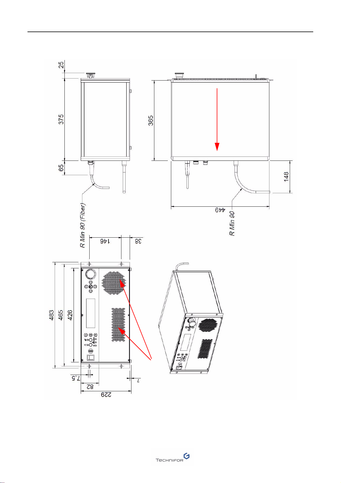
5. Dimensional drawings
TD412 dimensional drawing
Units: mm
Optical fiber: the optical fiber connecting the CCU tothe Laser module must never be bent to a radius of below 90 mm (3.543 in).
AOperating instructions for the machine C
Ref. DCD01/3078 - TD412_en_C 17/62
Dimensional drawing of the Control Unit in rack configuration - standard version
Units: mm
1 : Air vent
2 : Airflow direction
1
2

AOperating instructions for the machine C
Ref. DCD01/3078 - TD412_en_C 18/62
Dimensional drawing: Protective ring
The protective ring is screwed to the optical output of the marking head. The ring can be unscrewed and replaced
by a link system between the marking head and the marking area for particular integration.

AOperating instructions for the machine C
Ref. DCD01/3078 - TD412_en_C 19/62
6. List of accessories available upon request
The accessories mentioned below are available upon request.
Head accessories
Height adjustment device
Column stand
Mounting bracket(s)
Ez-Fix
Extra pair of glasses
Ref. 54807 • The CHR height adjustment system is used to adjust the
marking head height within a range of +/- 22.5 mm
(0.886 in).
• Positioned between the marking head and the support to
which the head is attached.
Ref. 58907
(Class 4)
• Marking machine support with height adjustment range of
300 mm (11.811 in).
• The marking head is attached to a column stand with a Z
axis. The Z axis is adjusted manually using the crank han-
dle and the ruler along the frame for positioning.
Ref. 58905
(Class 1 - with door)
• Marking machine support with height adjustment range of
50 mm (1.969 in).
• Compact Class 1 box with door for marking part up to
180 mm (7.087 in) high
Ref. 54808 This accessory is used to fasten the marking head on the height
adjustment device and on the column frame.
Ref. 66254 Used to rapidly fix small objects or items with various shapes.
Ref. 54577 Class 4: it is mandatory that the operator wear eye protection with
the suitable filter lenses.

AOperating instructions for the machine C
Ref. DCD01/3078 - TD412_en_C 20/62
Focal lens
1 : Marking area (mm)
2 : Focal lens
DMC 11
Fume extraction - filtration
Laser protection glass
Ref. 50944 100 mm (3.937 in) focal lens + adaptation ring
Ref. 64086 160 mm (6.299 in) focal lens
Ref. 72820 254 mm (10 in) focal lens
Ref. 54689 330 mm (12.992 in) focal lens
Ref. 53727 Key chuck
Pilots a rotating third axis (DMC) for marking on circular parts
Ref. 64892 Manual chuck
Pilots a rotating third axis (DMC) for marking on circular parts
Ref. ES10 Ref. ES30
Europe
60995 Europe
69835
• This accessory is used to extract fumes and
particles from materials.
• Range for different rates of air flow
Great Britain
60996 Great Britain
69836
Switzerland
60997 Switzerland
69837
USA
60998 USA
69838
Ref. 74924 Protection level of the laser shield for a 1064 nm wave length (LB6)
12
Table of contents


