DEGREE CONTROLS Cambridge Accusense ATM2400 User manual

Artisan Technology Group is your source for quality
new and certied-used/pre-owned equipment
• FAST SHIPPING AND
DELIVERY
• TENS OF THOUSANDS OF
IN-STOCK ITEMS
• EQUIPMENT DEMOS
• HUNDREDS OF
MANUFACTURERS
SUPPORTED
• LEASING/MONTHLY
RENTALS
• ITAR CERTIFIED
SECURE ASSET SOLUTIONS
SERVICE CENTER REPAIRS
Experienced engineers and technicians on staff
at our full-service, in-house repair center
WE BUY USED EQUIPMENT
Sell your excess, underutilized, and idle used equipment
We also offer credit for buy-backs and trade-ins
www.artisantg.com/WeBuyEquipment
REMOTE INSPECTION
Remotely inspect equipment before purchasing with
our interactive website at www.instraview.com
LOOKING FOR MORE INFORMATION?
Visit us on the web at www.artisantg.com for more
information on price quotations, drivers, technical
specications, manuals, and documentation
Contact us: (888) 88-SOURCE | sales@artisantg.com | www.artisantg.com
SM
View
Instra

50600MN000-Z01
ATM2400
Multi-Channel Airflow
and Temperature
Instrument
PRELIMINARY RELEASE. SEE DEGREE C WEBSITE FOR THE LATEST VERSION
User Manual
Artisan Technology Group - Quality Instrumentation ... Guaranteed | (888) 88-SOURCE | www.artisantg.com

www.degreeC.com
150600MN000-Z01
ATM2400 Instrument Series User Manual
© Copyright 2005 by Degree Controls, Inc.
All Rights Reserved. This publication may be reproduced for use of registered users of Degree Controls, Inc. products. For all
other purposes reproduction, storage or transmission in any form or by any means, electronic, mechanical, photocopying,
recording or otherwise, requires prior permission of Degree Controls, Inc.
Printed in U.S.A.
Part No.: SH50600
This publication may include words that are or are asserted to be proprietary names. The presence or absence of such
assertions should not be regarded as affecting the legal status of any proprietary name or trademark.
Cambridge Accusense ™ and AccuTrac™ are trademarks of Degree Controls, Inc.
Customer Service and Technical Support:
Mailing address:
Degree Controls, Inc.
18 Meadowbrook Drive
Milford, NH 03055 USA
Telephone: 603-672-8900 or 1-877-DEGREEC
Fax: 603-672-9565
Website www.DegreeC.com
Sales, Support, Service:Customer.service @degreec. com
Artisan Technology Group - Quality Instrumentation ... Guaranteed | (888) 88-SOURCE | www.artisantg.com

ATM2400
www.degreeC.com
250600MN000-Z01
Prefice A: Customer Service Information
This section provides information about Degree Controls, Inc.’s Customer Service policy, installation policy, and warranty. Degree
Controls, Inc.’s policies on warranty returns and consumable parts are also explained. To determine which policies apply to your
system, consult Degree Controls, Inc.
A1. Customer Service Policy
Degree Controls, Inc. has established a Customer Service department to meet the service needs of its customers. A Customer Service
Representative is available from 9:00 a.m. to 5:00 p.m. (EST) to:
A1.1 Take an order
A1.2 Track a shipment
A1.3 Determine availability
A1.4 Request technical support
A1.5 Request product and procedure training
A1.6 Record a problem
A1.7 Coordinate return of products
A1.8 Record a complaint or general feedback
For technical assistance, contact TechnicalSupport@Degree Controls, Inc.(1-877-DEGREEC):
Telephone troubleshooting with technical experts
Technical assistance to solve specific application questions
A2. Warranty Information
Degree Controls, Inc. products purchased in the USA or Canada are warranted to be free from defects in materials or workmanship
for a period of ninety days from the date of their original purchase. If a sensor or instrument fails to perform to this warranty, we
will, at our own option and at no cost to the customer, replace or repair it within a reasonable timeframe. This warranty does not
cover defects, malfunction, or failures resulting from shipping or transit accidents, misuse, operation contrary to furnished
instructions, modification, tampering, or normal wear and tear.
A3. Returns
Within the above period, any part of the goods that prove to be defective in material or workmanship may be repaired or replaced
on an exchange basis with a new or equivalent part free of charge.
After such warranty period, any labor, travel time, transportation and subsistence expense shall be borne by the Buyer. If preferred,
Buyer may return goods to Degree Controls, Inc.’s manufacturing plant with shipment both ways at Buyer’s expense for repair work.
Parts returned damaged due to poor or insufficient packaging by the Buyer will not be accepted for service unless otherwise agreed.
Parts returned with no manufacturing defects found, will incur a service/handling charge.
In no event shall Degree Controls, Inc. be liable for incidental or consequential damages, including, but not limited to, costs, or
removal and reinstallation or such goods, good will, overhead expenses, loss of profit, and loss of use.
The remedies are available only to the original Buyer. Buyer agrees to accept billing for service expense for service call resulting
from other than a Degree Controls, Inc. goods failure or other Degree Controls, Inc. fault.
A4. Consumables
Consumables can be ordered from Degree Controls, Inc. or from your Degree Controls, Inc. authorized distributor. Use only Degree
Controls, Inc. products or Degree Controls, Inc. approved products with your ATM2400. Degree Controls, Inc. shall not be liable for
damage to or malfunction of the system, which it deems was caused by the use of unauthorized materials. Please refer to the Parts
List in Appendix A when ordering.
Artisan Technology Group - Quality Instrumentation ... Guaranteed | (888) 88-SOURCE | www.artisantg.com

ATM2400
www.degreeC.com
350600MN000-Z01
Table of Contents
INTENTIONALLY LEFT BLANK
Artisan Technology Group - Quality Instrumentation ... Guaranteed | (888) 88-SOURCE | www.artisantg.com

ATM2400
www.degreeC.com
450600MN000-Z01
About this Manual
This User Manual provides the information necessary to obtain the maximum benefits from the Cambridge Accusense Brand
ATM2400 Instrument Series. All operating instructions, functional descriptions, illustrations, and other relevant information are
contained in this manual. Descriptions of the system hardware and user-interface operating software are included. You will also find
the theory of operation for the instruments and sensors they employ. Systematic instructions guide you through all installation
procedures, and tables identify and describe all software operating menus.
Starting Out
If you are placing your ATM2400 in service for the first time, Degree Controls, Inc. recommends working through this Manual
following the step-by-step instructions provided. If you need additional help at your site as you move through these procedures,
contact your regional Degree Controls, Inc. representative or Degree Controls, Inc.’s Technical Support for assistance in properly
installing and starting up your ATM2400 Series instrument(s).
Operator Assistance:
If you experience difficulty in running your ATM2400 Series instrument, sensors or software, please contact your Degree Controls,
Inc. Representative or Degree Controls, Inc. Tech Support. This Manual includes a “Frequently Asked Questions” list that discusses
many common system problems, possible causes, and corrective operator actions. The information given there is general.
Degree Controls, Inc.’s Customer Service is available weekdays from 9:00 AM to 5:00 PM Eastern Time. Please contact Degree
Controls, Inc. Tech Support at 1-877-DEGREEC or visit our website www.degreec.C.com for additional information.
Technical assistance is also available from Degree Controls, Inc. Sales Representatives and Distributors throughout the world. Please
check our web site for the representative or distributor in your area.
Design Change Notice
Due to design changes and product improvements, information in this manual is subject to change without notice. Degree Controls,
Inc. reserves the right to change hardware and/or software design at any time, which can affect the contents of this manual.
Degree Controls, Inc. assumes no responsibility for errors of omission or content in this manual. We will make every reasonable
effort to ensure that this user manual is up to date and corresponds with your shipped instrument(s) and sensors.
Artisan Technology Group - Quality Instrumentation ... Guaranteed | (888) 88-SOURCE | www.artisantg.com
ATM2400
www.degreeC.com
550600MN000-Z01
Types of Messages
NOTES, WARNINGS and CAUTIONS:
Below are important notices and safety instructions. Please read carefully, and follow all warnings and instructions
marked on the sensor and in this manual.
DANGER: INDICATES SITUATIONS THAT COULD RESULT IN THE INJURY OR DEATH OF A HUMAN OPERATOR
OR BYSTANDER. WARNINGS ARE PRINTED IN ALL UPPER CASE CHARACTERS IN BOLDFACE TYPE, BETWEEN
TWO HEAVY HORIZONTAL RULES, AS IN THE FOLLOWING EXAMPLE:
CAUTION: Indicates situations that could damage the Instrument and/or Sensors, or cause injury to an
operator. Cautions are printed in mixed upper- and lower-case characters in boldface type, between two
heavy horizontal rules, as in this example:
CAUTION: Failure to connect the instrument to the proper electrical voltage as specified herein could result
in damage to the power supply and instrument.
NOTES: indicate miscellaneous information. Notes are printed in mixed case characters, in normal type,
between two heavy horizontal rules, as in this example:
NOTE: For details on Degree Controls, Inc. customer service policies, refer to Preface A.
Artisan Technology Group - Quality Instrumentation ... Guaranteed | (888) 88-SOURCE | www.artisantg.com

ATM2400
www.degreeC.com
650600MN000-Z01
Dangers,Cautions, and Notes
Below are important safety instructions. Please read carefully, and follow all warnings and instructions.
DANGER; NEVER INSTALL OR OPERATE DEGREE CONTROLS, INC. INSTRUMENTS AND SENSORS WHILE IN CONTACT
WITH WATER. YOU MAY BE ELECTROCUTED!
DANGER: DO NOT TRY TO REPAIR AN INSTRUMENT OR SENSOR YOURSELF. THERE ARE NO CUSTOMER-
SERVICEABLE PARTS INSIDE. OPENING THE CASE PRESENTS A DANGER OF ELECTRIC SHOCK, AND VOIDS THE
DEGREE CONTROLS, INC. WARRANTY.
DANGER: IF ANY OF THE FOLLOWING CONDITIONS OCCURS, TURN OFF THE INSTRUMENT IMMEDIATELY,
UNPLUG THE POWER CORD FROM THE ELECTRICAL OUTLET, AND CONTACT DEGREE CONTROLS, INC.:
If smoke, abnormal noise, or any strange odor is present.
If liquid has been spilled over or into the instrument.
If the instrument has been dropped or damage is visible.
WHEN EXPERIENCING MALFUNCTIONS,CONTINUING TO USE INSTRUMENTS OR SENSORS IN THE EVENT
OF ANY OF THE ABOVE CONDITIONS CAN RESULT IN DAMAGE TO THE EQUIPMENT AND INJURY TO HUMAN
OPERATORS!
CAUTION: Avoid exposing the Instrument and sensors to dust, rain, and (condensing) water. Water can cause
shorts, corrosion, and, at a minimum, inaccurate readings.
CAUTION: Use a power cable that is properly grounded. Always use AC power cords that meet the local safety
standards, such as those listed below.
CAUTION:The ATM2400 and Sensors are ESD sensitive devices. When shipped, the units are packaged in ESD safe
bags. The instrument and sensors should be returned to their respective ESD safe bags when they are placed back
into the carrying case.
CAUTION: The ATM2400 Series Instruments and Sensors are designed for room air velocity and room
temperature measurement only. Air containing chemicals (for example, hazardous gases) may damage the UAS
sensor head. Note: Chemicals may change the heat capacity of the air so that the calibration of the UAS sensor is
no longer accurate.
NOTE: Avoid exposing the Instrument to direct sunlight or other heat sources. Do not store the equipment in an
extreme hot or cold environment.
NOTE: Keep the Instrument and Sensors away from magnets, motors, transformers, speakers, and televisions.
Front View
Artisan Technology Group - Quality Instrumentation ... Guaranteed | (888) 88-SOURCE | www.artisantg.com

ATM2400
www.degreeC.com
750600MN000-Z01
1. ATM2400 Series Instruments
1.1 General Description
The Cambridge Accusense ATM2400 Instrument Series is a family of sophisticated, self-contained instruments designed for
accurate, cost-effective multi-point evaluation of air velocity and air temperature measurements. Simultaneous, real-time
data collection is supported for over 100 sensors.
The ATM2400 Series is designed for laboratory applications. It can take measurements much more quickly than conventional,
single-point measuring instruments.
The ATM2400 Series embodies the proven accuracy, reliability, and versatility that are characteristic of Cambridge Accusense
systems. Frequent returns and field recalibration are not required, because the user can easily verify operation and accuracy
of any one sensor (and its channel) by comparing it against any other sensors (and their channels).
1.2 Applications
The ATM2400 is a stand alone USB Hub that interfaces with Cambridge Accusene airflow & air temperature sensors. Each ATM2400
can accept up to 36 sensors simultaneously.
The ATM2400 can be used in a wide range of applications and industries. Some examples follow:
1.2.1 Electronics Cooling Design
1.2.2 Fume Hood and Biosafety Cabinet Design and Testing
1.2.3 Process Control
1.2.4 HVAC
1.2.5 Medical Applications
1.2.6 Food Processing
1.2.7 Automotive
1.3 General Respnsibities
1.3.1 Customer’s Responsibilities
When your Instrument arrives, you are required to:
1.3.1.1 Check the exterior of the shipping container(s) for any exterior damage, then the interior of the
container(s).
1.3.1.2 If any damage is found, immediately notify both the carrier and Degree Controls, Inc. on the straight
bill of lading (supplied by the carrier), both verbally and in writing; you may also request an inspection by
the carrier. Such requests must usually be made within a specified period from date of shipment.
1.3.1.3 If no damage is found, compare the contents of the Inventory List against the contents of the shipping
container(s), to ensure receipt of all components.
CAUTION: The ATM2400 and sensors are ESD sensitive devices. The units are shipped packed in ESD safe bags. When returning the
devices to the carrying case, the units should be placed back in their ESD safe bags to prevent any potential ESD damage to the
devices.
1.3.2 Degree Controls, Inc.’s Responsibilities
1.3.2.1 A Degree Controls, Inc. service engineer is available via telephone, fax, or e-mail to assist customers in
performing the initial installation of your ATM2400 Instrument. Information about how to contact Degree
Controls, Inc. is available on page 4. Assistance is also available from sales representatives and distributors
throughout the world. Please check our web site for the Degree Controls, Inc. representative or distributor
in your area.
Artisan Technology Group - Quality Instrumentation ... Guaranteed | (888) 88-SOURCE | www.artisantg.com

ATM2400
www.degreeC.com
850600MN000-Z01
Artisan Technology Group - Quality Instrumentation ... Guaranteed | (888) 88-SOURCE | www.artisantg.com

ATM2400
www.degreeC.com
950600MN000-Z01
1.4 Environmental Requirements
Excessive moisture in the air might affect the instrument’s performance by changing the electrical conductivity on the surface of the
electrical components and circuit boards. Relative humidity in the operating environment between 5% and 95% (non-condensing) is
acceptable.
Avoid placing the Instrument and Sensors near heating outlets or other hot devices. Acceptable temperatures are:
1.4.1 Calibration temperature range: 0-70°C for standard UAS airflow and air temperature sensors. This is the range
where the sensor accurately reads airflow and temperature according to its specification.
1.4.2 Operational temperature range for sensor head: -20-70°C. The sensor head and sensor cable will not be damaged
if exposed to these temperatures.
1.4.3 Operational temperature range for ATM2400: 10-60°C. To prevent permanent damage to the ATM2400, UAS or
UTS sensors, connectors, USB cable, and power supply do not expose them to temperatures outside of this range.
Do not store in extreme hot or cold environments.
1.5 Using Multiple Instruments
1.5.1 Some applications require more than 36 airflow and air temperature channels; others require surface temperature
readings in addition to airflow and air temperature readings. For such cases, multiple ATM2400 instruments can
be used simultaneously on one Personal Computer. Degree Controls, Inc.’s AccuTrac 2005 software allows use of
multiple instruments or channels.
1.5.2 Each ATM2400 instrument requires its own USB port.
Artisan Technology Group - Quality Instrumentation ... Guaranteed | (888) 88-SOURCE | www.artisantg.com

ATM2400
www.degreeC.com
10 50600MN000-Z01
Artisan Technology Group - Quality Instrumentation ... Guaranteed | (888) 88-SOURCE | www.artisantg.com

ATM2400
www.degreeC.com
11 50600MN000-Z01
2. ATM2400 Airflow and Air Temperature Monitor
Multipoint measurement of air velocity as well as air and surface temperature are crucial steps in the new product development
process. These measurements, however, have traditionally been inexact, labor-intensive, repetitive, and tedious. The new
AccuSense ATM2400 has been designed to reduce cost, increase efficiency, improve accuracy and compress testing and evaluation
time. Furthermore, the ATM2400 expands on the capabilities of its predecessor, the ATM24, with the inclusion of thermocouple
sensors, improved airflow sensor accuracy, enhanced AccuTrac 2005 software, as well as an additional 12 channels.
2.1 General Information
The ATM2400 now allows you to perform simultaneous measurement of air velocity and of airflow and surface
temperatures at 36 locations. Multiple ATM’s can be connected together to measure up to 100 points. The information is recorded
in real-time, and can be analyzed as data is being collected. The ATM2400 uses the UAS Series of Airflow Sensors and UTS Series of
Thermocouple Sensors. Improved air velocity accuracy to ±5% of reading from 15°C to 35°C, with ±8% accuracy at the
operating limits of 0°C and 70°C further enhances the ATM2400 ’s performance.
2.2 Components
The ATM2400 kit contains the following:
2.2.1 ATM2400 USB Hub
2.2.2 AC power cord (US/Canada only)
2.2.3 USB Cable
2.2.4 Carrying case
2.2.5 UAS and/or UTS probes (as ordered) with Certificates of Calibration
2.2.6 Accutrac 2005 Installation CD
2.2.7 ATM-2400 Manual
2.2.8 25 mounting clips (HDW-000072)
2.3 Electrical Power
Power is supplied to the ATM2400 through an internal universal power supply, which accepts electrical power from standard wall
outlets that meet the following requirements:
2.3.1 100-250 VAC
2.3.2 Frequency: 50-60 Hz
WARNING: DO NOT ATTEMPT TO POWER THE INSTRUMENT WITH ANYTHING OTHER THAN THE ORIGINAL POWER SUPPLY.
NOTE: If you are using the ATM2400 in countries other than the United States and Canada, you will need a country specific power
cord. please contact your Degree Controls representative for more information.
2.4 Technical Specifications
Parameter
Technical Data
Input voltage
100-250VAC, 50-60 Hz
Power consumption
50 Watt max
Operating temperature range: Sensors
0° to 70°C
Operating temperature range: Instrument
0° to 70°C
Calibration temperature range:
0° to 70°C
Storage temperature range:
-40° to 85°C
Dimensions (LxWxH)
235 mm X 300 mm X 35mm
Weight
2.5 Kg (4.97 lb)
Table 2.4ATM-2400 Technical Specifications
Artisan Technology Group - Quality Instrumentation ... Guaranteed | (888) 88-SOURCE | www.artisantg.com
ATM2400
www.degreeC.com
12 50600MN000-Z01
3. Hardware Installation and Initial Power Up
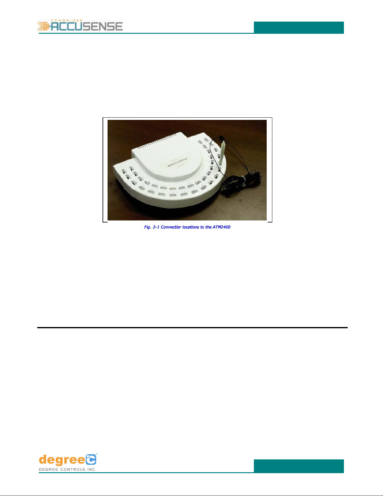
3.1 On the top of the ATM2400 unit (Figure 36 channels to connect up to 36 Sensors. On the back is the USB connector for linking
the system to the USB Port of the Computer.
3.2 Turning the instrument over, you will find the system information label on the bottom. It contains the instruments’part
number and serial number.
Figure 3 Connector Locations to the ATM-2400
3.3 After verifying that the ATM2400 instrument and sensors are complete as described earlier in this chapter, you are ready to
assemble the system.
3.3.1 Connect the external power cable to the ATM2400.
3.3.2 Connect the power cable to a wall outlet. For safety reasons a three-pin (grounded) outlet is required. The power
supply automatically adjusts for voltages between 100-250VAC, 50-60Hz.
3.3.3 Attach the desired number of sensors to the ATM2400. The sensors have USB connectors and plug in only one way.
Sensors can be plugged into any channel; empty slots may be left between sensors and will be ignored.
3.3.4 Plug the USB cable into the USB connector on the back of the ATM2400, and the opposite end into the USB port
on your PC.
NOTE: CHECKING CALIBRATION: UAS and UTS Sensor calibration information is contained in the sensor memory. The
information is available for review in Accutrac 2005.
Artisan Technology Group - Quality Instrumentation ... Guaranteed | (888) 88-SOURCE | www.artisantg.com

ATM2400
www.degreeC.com
13 50600MN000-Z01
Artisan Technology Group - Quality Instrumentation ... Guaranteed | (888) 88-SOURCE | www.artisantg.com

ATM2400
www.degreeC.com
14 50600MN000-Z01
4. UAS Series Airflow Sensors
4.1 Sensor Descriptions
The UAS1000 Series is an air velocity and air temperature sensor used with the ATM2400 Measurement System. The UAS1000 Series
offers many improvements with regards to accuracy and sensor ranges. With a variety of sensor ranges from 0.15 m/s to 20 m/s (30-
4000 fpm), the UAS1000 Series offers such features as miniature device size for multiple mounting configurations, improved
measurement accuracy with ±5% of reading from 15°C to 35°C, and 8% accuracy at the operating limits of 0°C and 70°C, ease of
installation, multipoint measurement, rugged construction, and probe interchangeability.
Three (3) unique sensor head styles, remotely located on a 5 meter shielded cable, allow access in distant and compact locations
such as between semiconductor devices, heat sinks, and inside ducts and plenums. These small heads cause minimal distortion of
the true airflow picture, and air velocity and airflow temperature measurements are obtained at the same time. Each one is
designed and optimized for certain types of applications. Please refer to the UAS Datasheets for more information on these sensors.
The UAS1000 Series sensors are also fully interchangeable with one another, as each sensor has its own in-line circuitry that
normalizes the performance of the sensor.
Simultaneous use of up to 36 UAS sensors with the ATM2400 data hub allows the user to have a snapshot of the airflow
environment at any given time. Multiple ATM2400’s can also be connected to a PC to obtain up to 100 data points. For surface
temperature measurement, please refer to the UTS1000/2000 Thermocouple Sensors datasheet. Both the UAS1000 and
UTS1000/2000 can be used simultaneously with the ATM2400 data hub to obtain airflow, air temperature, and surface temperature
in one instrument.
Figure 4
Plastic Case Sensor heads are contained in a plastic cover to protect them from being damaged under rough laboratory and
cleanroom environments. This sensor type is used perpendicular to the flow, with the air moving through both holes.
Low-Profile Sensors are designed for electronic cooling applications, where sensors are mounted on circuit boards, heat sinks and
components, and where size matters. This sensor type is used perpendicular to the flow, with the air moving through both holes.
XS (Extra Small) Sensors are shaped like the blade of a knife. They are designed to measure airflow and air temperature in tight
spots, e.g., between fins of a wider heat sink. The XS are arranged parallel to the flow, compared to the Clip-On and Low-Profile
Sensors, which are arranged perpendicular to the flow.
The standard medium is air at standard pressure (101.3 kPa, 29.95” Hg). For use with other gases, please contact Degree Controls.
Altitude compensation is available in the AccuTrac 2005 software package.
Artisan Technology Group - Quality Instrumentation ... Guaranteed | (888) 88-SOURCE | www.artisantg.com

ATM2400
www.degreeC.com
15 50600MN000-Z01
4.2 Technical Specifications
Parameter
Technical Data
Measurement Ranges
UAS1100 0.15 –1.0 m/s
UAS1200 0.50 –5.0 m/s
UAS1300 4.50 - 20 m/s
Sensor head options
LP - Low-profile Sensor
PC –Plastic case Sensor
XS - Blade Style Sensor
Standard cable length
5 meters unshielded
Operating temperature range
0 to 70°C
Storage temperature range
-40 to 85°C
Weight (UAS Head)
25 g (0.053 lb)
Air Velocity Accuracy
15°-35°C, ±5%. ±8% at
operating limits (0°C and
70°C)
Airflow Temperature Accuracy
0-70°C ± 1°C
Table 4.2: UAS 1000 Series Sensors Technical Specification
All three sensor heads are small in order to minimize disturbing the airflow. Air always takes the path of least resistance, which
makes it important not obstruct airflow.
Sensors are delicate and sensitive precision devices, but they are not unreasonably fragile. When not using the probes, put the
protective rubber caps back on. Always hold a sensor by the black heat shrink. Avoid directly touching the head itself, for it could
damage the thermistor beads, or disrupt their accuracy.
CAUTION: Thermistor beads are very hot. Touching them could cause burns to personnel.
4.3 Theory of Operation
Degree Controls, Inc. uses thermal anemometer technology for its airflow sensors. As illustrated in Fig. 3-6, a typical UAS sensor has
two thermistors (thermal resistor) mounted to each sensor. The smaller thermistor (or “bead”) measures airflow while
simultaneously the larger thermistor detects air temperature.
Fig. 4.3 Degree Controls, Inc. sensors measure airflow and air temperature simultaneously.
Using CTA (Constant Temperature Anemometer) technology, the airflow thermistor is heated; the amount of power required to
maintain the airflow thermistor at a constant temperature is equivalent to the heat lost due to the airflow passing by the thermistor.
The UAS sensor uses this information to calculate the velocity of the air passing by the sensor.
The ATM2400 can measure signals from up to 36 UAS sensors simultaneously. The data formatted by the ATM2400 is then available
for transfer to a personal computer.
TemperatureSensor
Artisan Technology Group - Quality Instrumentation ... Guaranteed | (888) 88-SOURCE | www.artisantg.com
ATM2400
www.degreeC.com
16 50600MN000-Z01
CAUTION: Do not attempt to measure surface temperatures using the UAS Sensors. When attached to a surface, the
heated airflow sensor could cause false readings.
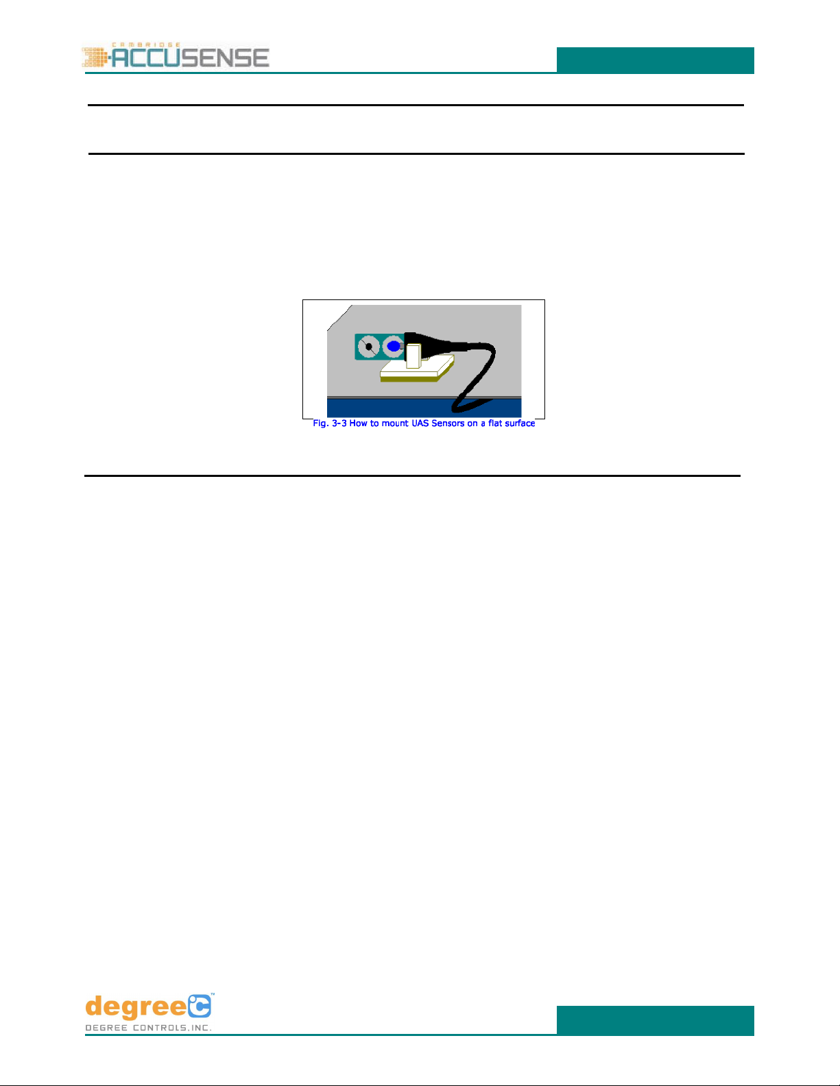
4.4 Mounting the Sensors on Flat Surfaces
For mounting Low Profile and XS-blade sensors in the air stream, Degree Controls, Inc. provides small self-adhesive mounting clips.
To attach the sensor to the plastic clip: Hold the sensor by the black heat shrink in one hand, the clip in the other. Insert the cable 2-
3" down from the sensor head through the two brackets of the clip. Turn the sensor in its intended position and slide the clip
towards the sensor head until it is approximately in the center of the heat shrink. Now peel the backing off the clip, and position the
clip at the predetermined location. To remove the sensor from the clip, slide it out from the clip 2-3" down the cable, and then
carefully pull the cable out from the prongs of the clip. If this is done carefully, the clip can be reused at its location.
Figure 4.4 How to mount UAS Sensors on a flat surface
CAUTION: Hold the sensor head only by the heat shrink and avoid touching the sensor beads.
Similar mounting clips are available from different vendors. For reordering Degree Controls, Inc. mounting clips, please contact the
Customer Service Department for part number HDW-000072.
4.5 Sensor Head Acceptance Angle
Typically, anemometer sensors are not uniformly shaped, which causes them to be direction-sensitive. It is therefore important to
know the orientation at which a sensor was calibrated, and what errors to expect if certain acceptance angles are exceeded.
Fig. 4.5.1 shows the acceptance angle of the Low Profile and Plastic Case airflow sensor heads. For calibration, sensors are installed
in the Degree Controls, Inc. wind tunnel perpendicular to the oncoming air stream. The air moves through the two holes in the
sensor head (Fig. 4.5.2), across the sensor beads. Due to the aerodynamics of the sensor head, misalignment can cause the airflow
to go around the sensor head rather than across the beads, which can lead to errors.
To learn about the limits of the technology, and to find the influence that the acceptance angle had on airflow sensor readings,
Degree Controls, Inc. performed the following experiment. Both a Plastic Case and Low-Profile Sensor were inserted into the airflow
of Degree Controls, Inc.’s wind tunnel at room temperature. Readings were then recorded with the sensors turned in increments of
5° from the original perpendicular position. This experiment was performed multiple times and at different speeds to ensure
repeatability.
Artisan Technology Group - Quality Instrumentation ... Guaranteed | (888) 88-SOURCE | www.artisantg.com

ATM2400
www.degreeC.com
17 50600MN000-Z01
Fig. 4.5.1 Accuracy sensors vs. angle from perpendicular of oncoming airflow
Figure 4.5.1 shows the results for Plastic Case and Low Profile sensors. The horizontal axis represents the angle, in degrees from
perpendicular, at which the sensor head was facing the oncoming airflow. On the vertical axis, the error in percent compared to the
sensor in ideal (perpendicular) position to the flow is displayed. This example shows how important it is to know the characteristics
of a sensor, which should be considered when interpreting results. It also shows that thermal anemometers are well suited for
applications where the direction of flow varies, like in electronics cooling applications, where the air moves irregularly and it is
difficult to predict the angle at which it approaches a sensor.
Fig. 4.5.2 Airflow acceptance angle as recommended by Degree Controls, Inc.
Fig. 4.5.2 shows the airflow acceptance angle as recommended by Degree Controls, Inc.. As long as this angle lies within an
imaginary cone with a 90° angle at the tip for Low Profile sensors, and 120° angle for Plastic Case sensors, the error from the
acceptance angle will not exceed 2% compared to a reading taken perpendicular to the airflow.
Table 4.5 shows the acceptance angle for three different sensor heads available.
Sensor head options
Acceptance Angle
Low-profile Sensor
Plastic Case Sensor Head
Extra Small Blade Style Sensor
±45°
±60°
±90°
Table 4.5 UAS Sensors Acceptance Angle
4.6 General Information on Measuring Airflow
Because air is invisible, measuring the speed of airflow has always presented a challenge. The ATM2400 is a useful tool for tracking
down air currents.
Most ATM2400 instruments are used in electronics cooling design, because air is the most commonly used medium to remove heat
from electronics enclosures. Knowledge of the air velocity plays an important role, as it provides information on the heat removal
rate and the thermal characteristics of the entire electronics system.
Artisan Technology Group - Quality Instrumentation ... Guaranteed | (888) 88-SOURCE | www.artisantg.com

ATM2400
www.degreeC.com
18 50600MN000-Z01
When air is used to remove heat from electronics enclosures, it is important to know the flow rate. The goal is to achieve the most
cooling effect with as little air as possible. Pumping enough air through the system to ensure an acceptable temperature even under
worst conditions, but at the same time keeping flow rates down to avoid acoustic noise requires careful planning. Space is a
premium, causing fan placement and fan size to be critical decisions in the design process. Knowing flow rates is essential for
gathering required parameters for CFD (Computational Fluid Dynamics) software, and for validating the results from the CFD
software.
Measuring airflow means tracking an invisible and compressible moving medium, which shows different characteristics depending
on conditions. According to theory, in a laminar flow all particles move in parallel tracks (layers) and in the same direction. In
turbulent flows the exchange is macroscopic and detectable, because the main current is superimposed by additional components
in x, y, and z directions (eddy-currents). The change from laminar to turbulent flow happens when the Reynolds Number reaches
critical levels, which depends on a number of parameters such as shape and cross section of flow.
Airflow in electronics cooling is usually very turbulent due to fans, obstacles, and heat sources. Therefore measuring velocities
requires sensors that are capable of sensing accurately under such conditions, while minimizing further disturbance of the flow.
For many reasons, thermal anemometers are the best tools available for measuring airflow in electronics cooling. Thermal sensors’
small size minimizes obstructions in a crowded enclosure. They have a fast response time and high sensitivity, allowing
measurement of turbulence intensity. Thermal sensors are available with most standard interfaces, are very reliable, and relatively
low-cost.
Thermal anemometry is a method of determining fluid velocities by measuring the heat transfer rate from a heated small object like
a wire, film, or thermistor located in the flow. The rate at which heat is removed from the sensor is directly related to the velocity of
the fluid flowing past the sensor. Constant Temperature Thermal anemometers (CTA) work like a finger held up in the wind. Kept at
a constant temperature above ambient, the device is cooled by passing air. The power required to maintain a constant temperature
is then used to calculate the air speed.
Thermal anemometry is a flexible, accurate, and almost entirely automated method of flow measurement. It can be applied to
nearly any flow, where the physical presence of a sensor does not adversely affect the current, or where contaminants in the flow
do not damage the sensor. It is particularly appropriate for applications requiring rapid response to flow changes (turbulence
measurements), and where cost limitations are a factor.
Heated anemometers are best characterized by the heat transfer rate, which describes the heat loss dependent on multiple factors:
temperature, pressure, content of gas, and nature of flow. Not all of the above have the same influence on measurement, but each
one should be considered to achieve accurate readings.
Temperature: Thermal anemometers require temperature compensation because the heat transfer rate depends on the
temperature differential between the heated sensor and ambient air. The greater the temperature differential, the greater the heat
loss and, consequently, the greater the signal. However, a hot device can also alter the nature of the flow by adding heat, or causing
warm air to rise.
Pressure: Molecules carry heat. Below standard pressure (760mm Hg, 101.3kPa), e.g. at high altitude or in a vacuum chamber, a
lower number of molecules is available to carry away heat from the heated sensor, which will then read low. Above standard
pressure, additional cooling is provided due to an increased number of molecules, and the heated sensor would read high. Heated
anemometers therefore need to be pressure compensated.
Content of gas: Thermal anemometers usually are calibrated for air in human environments. When such a sensor is used with gases
different from room air, the calibration might no longer be accurate due to different heat capacity and heat transfer rate of the
medium. Aggressive chemicals could damage the probe, and deposits on the probe head may alter aerodynamics and affect the
accuracy of readings. Humidity does not necessarily change heat transfer rates significantly. Studies show that there is less than a
3% change in the velocity reading while relative humidity changes from 5 to 95% in air at room temperature. However, water
condensing on the sensor can cause calibration errors.
Nature of Flow: Air forced through tight openings or nozzles shows different characteristics than a current moving along a straight
duct. Fans can generate heavily turbulent flows in a corkscrew-like pattern even far downstream. Components on a circuit board or
obstacles in ducts are likely to redirect flow, which tends to follow the path of least resistance. Rapid pressure changes are likely
where gases are forced through nozzles, tight openings or close to fast-turning fans. Air is a compressible medium, and due to its
invisibility may exhibit unforeseeable behavior that could affect readings of thermal anemometers. It is therefore always advisable
to verify results.
Artisan Technology Group - Quality Instrumentation ... Guaranteed | (888) 88-SOURCE | www.artisantg.com
Table of contents
Other DEGREE CONTROLS Measuring Instrument manuals


