Technische Alternative CAN-BC2 Installation guide
www.ta.co.at
Manual version 1.15.1 English
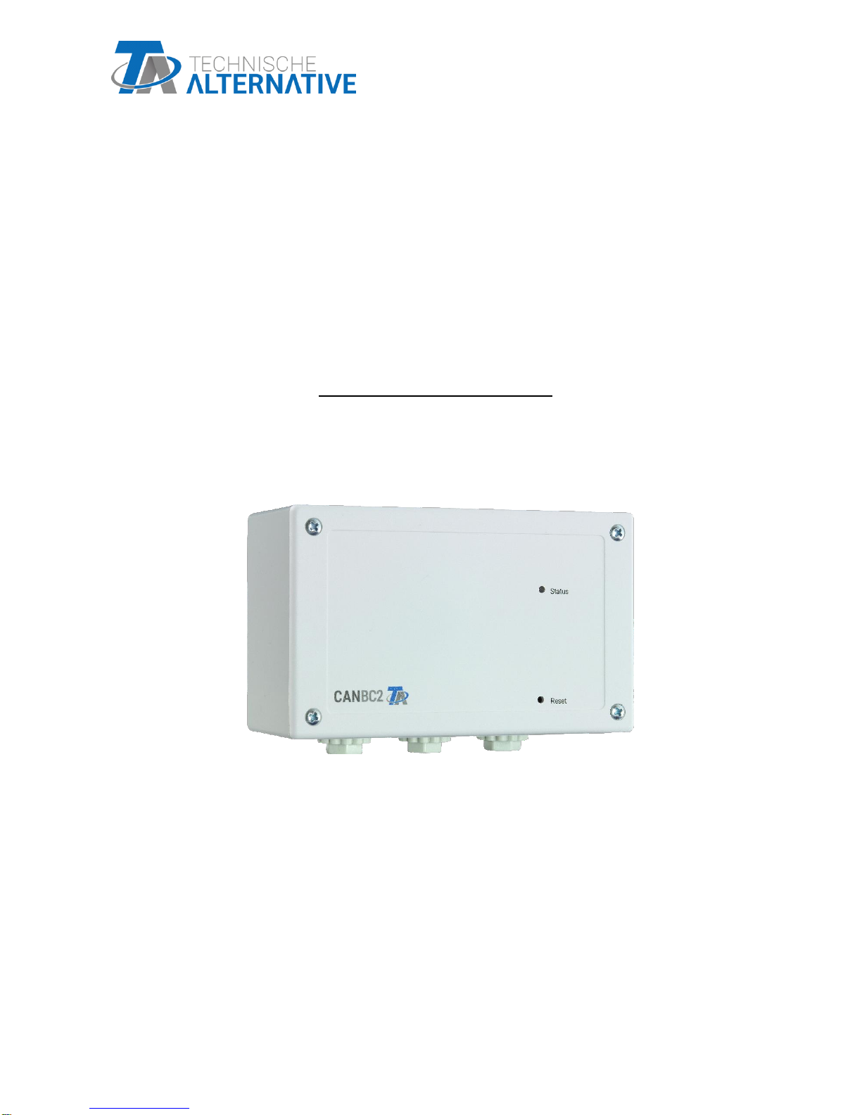
CAN-BC2
CAN-Bus converter
Installation instructions
Programming manual


Table of contents
Version 1.15.1 EN
Disposal...............................................................................................................................................5
Standard delivery.................................................................................................................................5
Installing and connecting the device ...................................................................................................5
Fixing dimensions and measurements......................................................................................................... 5
Power supply............................................................................................................................................... 6
CAN bus cable selection and network topology ........................................................................................... 6
DL bus and M-Bus connections ................................................................................................................... 9
Data link for DL bus .............................................................................................................................................9
Bus load from DL sensors..............................................................................................................................9
M-Bus cable..........................................................................................................................................................9
Principles.......................................................................................................................................... 10
Minimum system requirements ................................................................................................................. 10
Interfaces .................................................................................................................................................. 10
Potential-free CAN bus with increased interference resistance.................................................................... 10
M-Bus (measurement bus)............................................................................................................................... 10
DL bus................................................................................................................................................................ 11
Modules............................................................................................................................................................. 11
KNX module MD-KNX.................................................................................................................................. 11
Modbus/M-Bus module .............................................................................................................................. 11
Programming with TAPPS2.............................................................................................................. 12
Designations.............................................................................................................................................. 12
User defined designations................................................................................................................................ 12
Fixed values............................................................................................................................................... 14
Fixed value type ................................................................................................................................................ 14
Digital ........................................................................................................................................................... 14
Analogue...................................................................................................................................................... 15
Pulse............................................................................................................................................................. 15
Designation ....................................................................................................................................................... 16
Restriction of change authority........................................................................................................................ 16
Functions................................................................................................................................................... 17
Selecting a new function .................................................................................................................................. 17
Designation ....................................................................................................................................................... 17
Input variables................................................................................................................................................... 18
Parameters........................................................................................................................................................ 20
Hystereses ................................................................................................................................................... 21
Function quantities (units).......................................................................................................................... 23
Output variables................................................................................................................................................ 24
CAN bus .................................................................................................................................................... 25
CAN settings for the converter ........................................................................................................................ 25
Datalogging ....................................................................................................................................................... 26
CAN analogue inputs........................................................................................................................................ 28
Node number ............................................................................................................................................... 28
Designation.................................................................................................................................................. 28
CAN bus timeout ......................................................................................................................................... 28
Unit ............................................................................................................................................................... 29
Value at timeout .......................................................................................................................................... 29
Sensor check ............................................................................................................................................... 30
Sensor error ................................................................................................................................................. 30
CAN digital inputs ............................................................................................................................................. 30
CAN analogue outputs ..................................................................................................................................... 31
Designation.................................................................................................................................................. 31
Transmission condition .............................................................................................................................. 31
CAN digital outputs........................................................................................................................................... 32
Designation.................................................................................................................................................. 32
Transmission condition .............................................................................................................................. 32
DL bus ....................................................................................................................................................... 33

DL settings......................................................................................................................................................... 33
DL input.............................................................................................................................................................. 33
DL bus address and DL bus index............................................................................................................... 33
Designation .................................................................................................................................................. 34
DL bus timeout............................................................................................................................................. 34
Unit................................................................................................................................................................ 34
Value at timeout........................................................................................................................................... 34
Sensor check................................................................................................................................................ 35
Sensor error.................................................................................................................................................. 35
DL digital inputs ........................................................................................................................................... 35
Bus load from DL sensors........................................................................................................................... 35
DL output ........................................................................................................................................................... 36
M-Bus........................................................................................................................................................ 37
Settings.............................................................................................................................................................. 37
M-Bus input........................................................................................................................................................ 38
General ......................................................................................................................................................... 39
Designation .................................................................................................................................................. 39
Unit................................................................................................................................................................ 40
Sensor correction ..................................................................................................................................... 40
Value at timeout ....................................................................................................................................... 40
Sensor check................................................................................................................................................ 40
Sensor error.................................................................................................................................................. 40
System values ........................................................................................................................................... 42
Device settings.......................................................................................................................................... 43
General............................................................................................................................................................... 43
Currency ....................................................................................................................................................... 43
Technician / Expert password .................................................................................................................... 43
Access to menu ........................................................................................................................................... 43
Time / location............................................................................................................................................. 44
Bus settings....................................................................................................................................................... 44
C.M.I. Menu.......................................................................................................................................45
Date / time / location ................................................................................................................................. 45
Value summary.......................................................................................................................................... 47
Fixed values .............................................................................................................................................. 48
Changing a digital fixed value .......................................................................................................................... 48
Changing an analogue fixed value ................................................................................................................... 49
Activating a fixed pulse value........................................................................................................................... 49
General settings ........................................................................................................................................ 50
Version and serial number......................................................................................................................... 51
Messages.................................................................................................................................................. 52
User........................................................................................................................................................... 53
Current user....................................................................................................................................................... 53
List of permitted actions................................................................................................................................... 54
Data administration ................................................................................................................................... 55
C.M.I. - Data administration menu ................................................................................................................... 55
Total reset .................................................................................................................................................... 55
Restart .......................................................................................................................................................... 55
Loading function data or updating firmware via C.M.I. .................................................................................. 56
Loading function data or updating firmware via UVR16x2 or CAN-MTx2 ..................................................... 57
Reset.................................................................................................................................................59
LED status indicators ........................................................................................................................59
Technical data...................................................................................................................................60
Installing and connecting
5
Disposal
➢Devices no longer in use or beyond a state of repair must be disposed of in an
environmentally responsible manner by an authorised collection point. They must
never be treated as ordinary household waste.
➢We can undertake the environmentally responsible disposal of devices sold by
Technische Alternative upon request.
➢Packaging material must be disposed of in an environmentally responsible manner.
➢Incorrect disposal may result in considerable damage to the environment, as many
of the materials used require professional handling.
Standard delivery
•CAN-BC2 CAN bus converter
•2x terminal (4-pole)
•2x terminal (2-pole)
•Plastic wall plugs
•Clamping plate screw
•Operating instructions
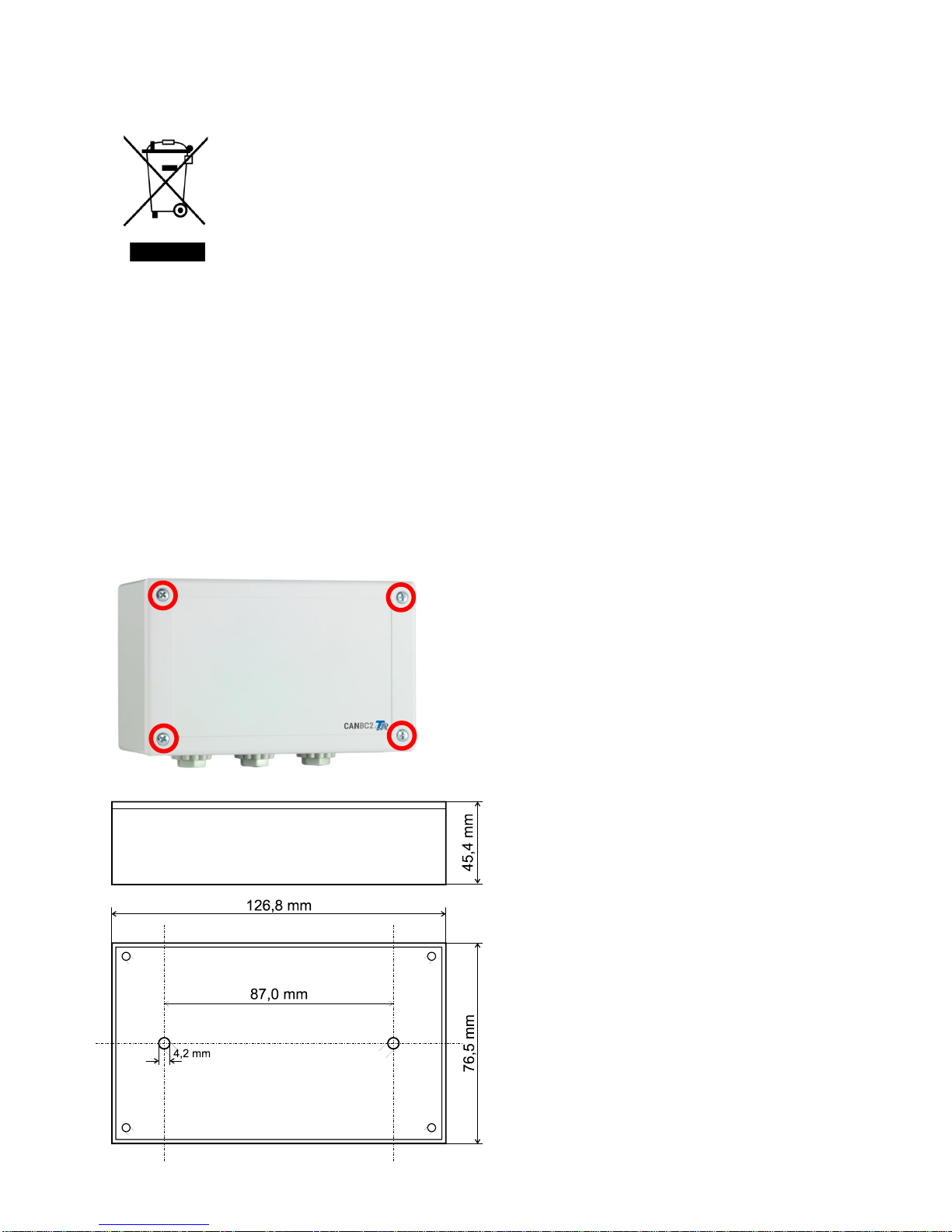
Installing and connecting the device
The CAN-BC2 is integrated into a distribution box or fitted to a level mounting surface in a dry room, in
accordance with local regulations. It can be snapped onto a top-hat rail (TS35 DIN support rail to
EN 50022) or bolted onto the mounting surface via the 2 holes in the casing tray.
Unscrew the 4 screws on the front and lift the cover.
Fixing dimensions and measurements

Installing and connecting
6
Power supply
The bus converter requires a 12 V power supply provided by the CAN bus network. The supply comes
from one side of the CAN bus network only, as the other side is potential-free, i.e. the 12 V power
supply is not looped through.
CAN bus cable selection and network topology
The principles of CAN bus cabling are described extensively in the manuals for the freely
programmable controllers and must be observed.
This manual describes only certain features that are specific to this device.
Each CAN network must be provided with a 120 ohm bus terminator at the first and last network node
(termination –with plug-in jumper). A CAN network therefore always has two terminators (one at
each end). The potential-free separation by the bus converter requires a plug-in jumper to be set in
accordance with the CAN network topology. This jumper is located on either side of the CAN bus.
Potential-free
CAN bus network
(CAN bus 2)
Power
supply
Potential-free
CAN bus network
CAN bus

Installing and connecting
7
Example: Network across several buildings with CAN bus converter CAN-BC2
Key to symbols:
… Device with its own power supply (UVR16x2, RSM610, UVR1611)
… Device is supplied by the bus (CAN I/O, CAN-MT, …)
… CAN bus converter (CAN-BC2)
… Terminated (end devices) … Open termination
… CAN bus surge arrester ... Gas discharge arrester for indirect earthing
e.g. CAN-UES, CAN-UES2
With CAN bus surge arresters: The screen of the disconnected network is connected to CAN bus
earth (GND) for each bus converter. This screen must not be directly earthed.
The CAN bus converter is similar to a repeater. It receives CAN bus signals and passes them on. Each
cable run on either side of the CAN bus converter must therefore be viewed as an independent CAN
bus network.
Max. cable length: Subject to bus rate set in the disconnected network (CAN bus 2)
Indirect earthing
Indirect earthing
Indirect earthing
optional

Installing and connecting
8
Without CAN bus surge arresters: This version only protects against potential differences up to 1 kV
and cannot be considered to offer lightning protection. In this case, the cable screen must be earthed
at a single point between the CAN bus converters, as close to the cable centre as possible. We
recommend earthing the screen indirectly in the other buildings using a gas discharge arrester.
Branch cables
As a general principle, branch cables are not permitted in a CAN bus network.
The CAN bus converter is used to provide reliable long branch cables. This means the branch cable is
disconnected from the other CAN bus network and can be viewed as an independent CAN bus
network.
Independent
CAN bus
network
Indirect earthing
Indirect earthing
Indirect earthing
optional

Installing and connecting
9
DL bus and M-Bus connections
The polarity of the M-Bus connection is reversible.
Data link for DL bus
The DL bus has 2 wires: DL and GND (sensor earth). The DL bus itself supplies the power supply for
the DL bus sensors.
Cables can be routed with a star topology or in series (from one device to the next).
Any cable with a cross-section of 0.75 mm² up to 30 m in length can be used as a data link. For longer
cables, we recommend the use of a screened cable.
Long cable conduits routed closely next to each other for mains and data links result in faults being
induced into the data link from the mains. We therefore recommend a minimum clearance of 20 cm
between two cable conduits or the use of screened cables.
Never run the data link together with a CAN bus cable or M-Bus cable in the same conduit.
Bus load from DL sensors
A 2-pole cable provides both the power supply and the signal transfer from DL bus sensors. An
additional power supply by means of an external power supply unit (such as with the CAN bus) is not
possible.
Take the "bus load" into consideration as sensors have a relatively high current demand:
The bus converter supplies the maximum bus load of 100 %. The bus loads of the electronic sensors
are listed in the technical data of the relevant sensors.
Example: The electronic sensor FTS4-50DL has a bus load of 25 %. Consequently up to four
FTS4-50DL sensors can be connected to the DL bus.
M-Bus cable
The M-Bus has 2 wires: M-Bus and GND (sensor earth). The power supply for reading data from M-
Bus devices is provided by the bus converter.
Cables can be routed with a star topology or in series (from one device to the next). Ring topology is
not permitted.
A two-wire screened cable is used as the M-Bus cable (e.g. telephone cable J-Y(ST)Y 2 x 2 x 0.8 mm).
The maximum total cable length depends on the number of M-Bus devices connected and the cable
cross-section.
Never run the M-Bus cable together with a CAN bus cable or DL bus cable in the same conduit.

Principles
10
Principles
The CAN bus converter makes additional interfaces available for all CAN bus devices.
Furthermore, all the function modules in the X2 range are available. These allow bus input values to
be processed directly in the bus converter. The results of the functions can be transferred to other
devices as network outputs, visualised or logged.
It is programmed using TAPPS2 software. The CAN-BC2 can be operated via the UVR16x2 controller,
via CAN-MTx2 or via the C.M.I. interface.
Minimum system requirements
Programming: TAPPS2 version 1.10
Programming
Visualisation: TA-Designer version 1.17
Access: C.M.I. version 1.26.2
UVR16x2 version V1.23
CAN-MTx2 version V1.09
Datalogging: Winsol version 2.07
Interfaces
Potential-free CAN bus with increased interference resistance
The CAN-BC2 is used for remote connection within a controller network or by network groups. This
could be several groups of CAN bus connections and/or further remote CAN bus subscribers, for
example in a heating system.
This interface is electrically isolated from the primary CAN bus via an optical transmission path.
We recommend using a bus converter at both ends of a long cable, so that no critical electronic parts
are directly connected to the bus over the entire remote connection. The CAN-BC2 protects against
potential differences of up to 1 kV and can therefore not be considered to offer voltage surge
protection in the case of a lightning strike.
Note: Every CAN bus subscriber is identified with its own CAN node number from a total of
62 possible node numbers. When designing the network, bear in mind that a bus converter does not
disconnect the networks from a data point of view and therefore does not increase the number of
nodes available. As bus subscribers, every single converter is given its own node number. This
individual number is identical for both CAN sides (primary and potential-free).
M-Bus (measurement bus)
The M-Bus is a master/slave system for reading data from energy and volume meters (electricity,
heat, water, gas).
The CAN-BC2 is designed for up to 4 M-Bus "unit loads". Up to 4 M-Bus meters, each with 1 unit load,
can therefore be connected. The bus converter (master) cyclically reads the values from the individual
devices. The interval time is adjustable.
As a master, this bus converter is therefore suitable for the parallel connection of up to four
M-Bus meters (slaves).
In total, a maximum of 32 M-Bus values can be read per bus converter. There must only be one
master in the M-bus system.

Principles
11
DL bus
The DL bus was developed by Technische Alternative and is designed to read measurements from DL
sensors.
It has just 2 wires: DL and GND (sensor earth). The DL bus itself supplies the power supply for the
DL bus sensors.
Modules
The number of interfaces can be increased through the use of modules. Only one extension module
can be used at a time in the CAN bus converter. These modules are described extensively in their own
manuals.
KNX module MD-KNX
This module helps to make it possible to connect the CAN bus network to the KNX bus network. Up to
64 values can be exported to the KNX bus and 64 values can be imported from the KNX bus.
Modbus/M-Bus module
This module has a Modbus RTU 485 interface which can be configured as either master or slave. Up
to
64 values can be exported to the Modbus and 64 values can be imported from the Modbus.
In addition, the module has an interface for reading data from a further four M-Bus meters. A further
32 M-Bus values can therefore be read.

Programming with TAPPS2 / Designations
12
Programming with TAPPS2
The following describes how to program the parameters for all elements using the TAPPS2
programming software.
Designations
All elements can be designated by selecting a predefined designation from various designation
groups or from the user defined designations.
You can also assign a number from 1 to 16 to every designation.
User defined designations
Up to 100 different designations can be defined by the user. The maximum number of characters per
designation is 24.
Designations defined previously are available for all elements (functions, fixed values, bus inputs and
outputs).
Example:
You want to assign a user defined designation to CAN input 1.
Click the field for creating the required
designation.

Programming with TAPPS2 / Designations
13
Enter the designations, finish with "OK"
Select from the list of previously created user
defined designations.
The required designation is displayed

Programming with TAPPS2 / Fixed values
14
Fixed values
In this menu you can define up to 64 fixed values, which can be used as input variables for functions,
for example.
Example:
Fixed value type
Once the required fixed value is selected, the fixed value type can be defined.
•Digital
•Analogue
•Pulse
Digital
Select the measured variable:
•Off / On
•No / Yes
Select whether the status can be changed
via a selection box or simply by a click.

Programming with TAPPS2 / Fixed values
15
Analogue
Select from a wide range of units and dimensions
After assigning the designation, you must
define the permitted limits and the current
fixed value. The value can be adjusted in the
menu within those limits.
Pulse
A fixed value of this type allows short pulses to be generated by tapping it in the menu.
Example:
Select the function quantity: when activated,
either an ON pulse (from OFF to ON) or an
OFF pulse (from ON to OFF) will be
generated, depending on the selection made
here.
Programming with TAPPS2 / Fixed values
16
Designation
Enter the fixed value designation by selecting a predefined designation or one of the user defined
designations.
You can also assign a number from 1 to 16 to every designation.
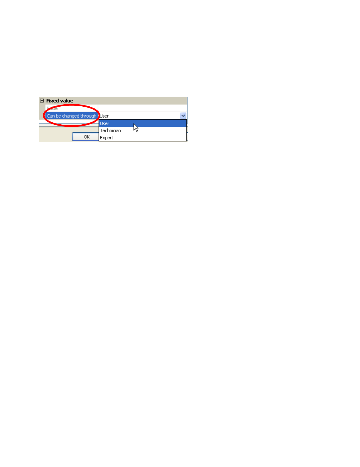
Restriction of change authority
For all fixed values, you can set the user level from which the fixed value can be changed:

Programming with TAPPS2 / Functions
17
Functions
You can choose from 41 different functions and create up to 22 functions. Functions can also be
applied multiple times.
Input variables are assigned to every function. The input variables provide the function with all the
data required for the internal decision.
Each function can be activated or deactivated with "Enable".
Within each function, data and parameter settings are utilised in order to calculate the decisions and
set values, which are then made available as output variables.
A function can therefore only perform tasks in the overall system when connected by its respective
input and output variables to other parts of the system (other functions or the network).
The individual function modules are described in the UVR16x2, RSM610 and CAN-IO 45 manuals. This
manual only provides general information on how to program functions.
Selecting a new function
Working with TAPPS2 is described in the manual for TAPPS2
(see "Help / Manual" menu item or "F1" key in TAPPS2).
Designation
After selecting and inserting the function in the drawing interface, you define the function designation.
Example: Analogue function
Enter the function designation by selecting a predefined designation from a "general" designation
group or from user defined designations.
You can also assign a number from 1 to 16 to every designation.
How to create user defined designations is described in the "Designations"chapter.

Programming with TAPPS2 / Functions
18
Input variables
Input variables constitute the link to output variables from other function modules or other sources.
The descriptions of the function modules state the signal type for every input variable. Digital input
signals (ON/OFF) can be applied as standard or inverse.
Every function module has the "Enable" input variable, which represents the fundamental activation of
the entire function. It permits simple blocking or enabling of the entire function by means of a digital
signal (ON/OFF).
Example: Analogue function
The following source types are
available to choose from:
•User
•Functions
•Fixed values
•System values
•DL bus
•CAN bus analogue
•CAN bus digital
•M-Bus
•KNX bus (only if module is fitted)
•Modbus (only if module is fitted)
Important: For every input variable, it is important to note the input signal type:
Analogue (numeric value) or digital (OFF/ON).

Programming with TAPPS2 / Functions
19
Certain input variables are always essential for the function to operate and cannot be set to "unused".
They appear in purple in TAPPS2 and are highlighted in the description of the functions. Others can
be optionally linked to sources.
Example: TAPPS 2
Depiction in the manual:
After linking to the source, you define which information (which variable) from the source will be
transferred to the function.
Example: CAN bus analogue
•Measurement –the value measured
•RAS mode –subject to the setting of the switch on the room sensor (RAS, RASPT, RAS-PLUS,
RAS-F), the following analogue values will be issued:
Automatic 0
Standard 1
Lowered 2
Standby 3
•Sensor error –digital value; ON if a sensor error occurs
•Network error –digital value; ON if a timeout is active (= error). This application is not yet
available for the M-Bus.
When linked to a function, the output variables are displayed for selection.

Programming with TAPPS2 / Functions
20
Parameters
These parameters are values and settings which are specified by the user.
They are settings which allow users to adjust the module to match the properties of their system.
Example: Comparison function
The parameters menu may also be divided into further sub-menus in the C.M.I. view, depending on the
function.
If optional sensors are not used, the settings for them are shown in grey and they cannot be
programmed.
Example: Solar control, limit temperature input variable is unused
Input variable
Parameter
Table of contents


