Trinity Amps TC15 User manual

The Trinity Amps
TC15
Amp Builder's Guide
February 2021, Version 21.2
For the sole personal use of Trinity Amps Customers.
Parts © Trinity Amps 2005 - 2021
www.trinityamps.com


Table of Contents
Thank You! .......................................................................................................................................................5
Introduction......................................................................................................................................................7
Acknowledgements ........................................................................................................................................7
WARNING .......................................................................................................................................................8
Version Control................................................................................................................................................9
Builders Guide General Theory............................................................................................................... 10
Building an Amp .......................................................................................................................................... 11
Introduction...................................................................................................................................................11
Switches and wire..........................................................................................................................................11
Physical layout ...............................................................................................................................................11
Grounding......................................................................................................................................................11
Insulated jacks ...............................................................................................................................................12
Minimizing transformer interference......................................................................................................... 12
Wiring .............................................................................................................................................................12
Assembling the amp.................................................................................................................................... 12
Before You Begin ......................................................................................................................................... 12
Tools ...............................................................................................................................................................12
Soldering.........................................................................................................................................................13
Tube Pin Numbering ...................................................................................................................................13
Tube Designations........................................................................................................................................ 14
Grounding Scheme............................................................................................................................... 15
Assembly Steps Summary.......................................................................................................................... 15
1. Install the Hardware ...........................................................................................................................16
Tube Sockets.......................................................................................................................................... 18
Can Capacitor ........................................................................................................................................ 18
Grommets .............................................................................................................................................. 18
Front Panel............................................................................................................................................. 18
Terminal Strips ...................................................................................................................................... 18
Ground Lugs.......................................................................................................................................... 19
Output Jacks .......................................................................................................................................... 20
IEC Mains Socket ................................................................................................................................. 20
Fuse Holder ........................................................................................................................................... 20
2. Heater Wiring ......................................................................................................................................21
Heater Wires .......................................................................................................................................... 21
3. Install Transformers ...........................................................................................................................22
4. Wire the Power Supply ......................................................................................................................22
120V MAINS......................................................................................................................................... 25
240V MAINS......................................................................................................................................... 26
Wiring the Rectifier............................................................................................................................... 27
Test the Power Supply ......................................................................................................................... 29
5. Assemble the Turret Board ...............................................................................................................30
Install Components on Turret Board................................................................................................ 30
Install the Turret Board ....................................................................................................................... 33
6. Connecting the Turret Board............................................................................................................34
Tube Sockets.......................................................................................................................................... 34
Socket Mounted Resistors................................................................................................................... 36
Phase Inverter Socket........................................................................................................................... 36
Power Tube Wiring and Screen Resistor .......................................................................................... 36

Trinity Amps TC15 Builder’s Guide. Version 21.1 Page - 4
Connecting Controls - Potentiometers.............................................................................................. 37
TC15 Tone Contour Wiring................................................................................................................ 38
Master Volume Switch –Master Cut................................................................................................. 40
7. Output –Transformer, Impedance Switch, Jacks .........................................................................40
Crunch - Munch Switch....................................................................................................................... 40
Connecting the Impedance Selector .................................................................................................. 42
Output Jacks .......................................................................................................................................... 44
8. Input - Jacks and Input Grid Resistors ...........................................................................................45
Input Grid Resistors............................................................................................................................. 45
Input Jacks ............................................................................................................................................. 45
Combo Chassis Cliff Jack Wiring....................................................................................................... 46
Preparing Co-Axial Wire...................................................................................................................... 47
Final checkout............................................................................................................................................... 48
Power Up ........................................................................................................................................................ 49
Working Inside a Tube Amplifier Safely...................................................................................................49
Unplug .................................................................................................................................................... 49
Sit............................................................................................................................................................. 49
Drain ....................................................................................................................................................... 49
Test.......................................................................................................................................................... 49
Close........................................................................................................................................................ 49
Making a Voltage Measurement ................................................................................................................. 50
Trinity TC15 Voltages (Black Turret Board)....................................................................................... 52
WARNING .................................................................................................................................................... 53
Read this Information Carefully......................................................................................................... 53
Builders Guide General Troubleshooting ............................................................................................ 53
TC15 Tone Tweaking ................................................................................................................................. 53
Tube Substitutions ...................................................................................................................................... 57
How to read Resistor Color Codes ......................................................................................................... 58
How to Read Capacitor Codes ................................................................................................................ 59
FAQ.................................................................................................................................................................. 61
Cliff Jacks Explained................................................................................................................................... 64
TC15 - BILL OF MATERIALS (BOM)................................................................................................ 65
TC15 –POWER TRANSFORMER SCHEMATICS ....................................................................... 68
Trinity Amps Schematics and Layouts ................................................................................................. 70

Thank You!
Thank you for purchasing your kit from Trinity Amps. We truly hope that you enjoy building it. If
you have any questions please do not hesitate to contact us.
We are always looking for feedback form our Customers on our products. We have checked the
build instructions over thoroughly and are confident in our product. However, mistakes do happen
so our advice is that as you connect each wire and part according to the layout, cross-check against
the schematic. If you find any inconsistencies, or have any concerns, please let us know. Do not
hesitate to contact us! We want this build to be successful for you and for Trinity Amps!
Please check over your parts carefully and the Bill of Materials and notify us of anything that does
not seem correct.
We’re confident that you will like our product and our support and when you’re completed, we’d
appreciate your comments posted on any of the internet forums such as thegearpage.net,
18watt.com, AX84.com or trinityamps.com. You will find some extra business cards in the package.
Please keep one and pass the rest around.
We know you have a choice in suppliers and we do appreciate your business.
Have Fun!!
Cheers,
Stephen Cohrs,
Trinity Amps
Web site: www.trinityamps.com
email: [email protected]


Introduction
This guide has been prepared for builders of Trinity Amps Kits. It is always being improved and we
Accordingly, content and specifications are subject to change without notice.
We do try to make it as accurate as possible, but it is sometimes hard to keep up with the changes.
Therefore, if you do find an error, please let us know about it and we will correct it. Suggestions are
welcome so if you have one, please get in touch with us.
Sources of help.
Forums: Please use the various forums to get help. They are an excellent resource and can be found at
trinityamps.com, AX84.com, the Gear Page etc..
Color assembly pictures and the latest drawings, tips, techniques are all in the Trinity Amps Forum, in
the Resources Forum.
Email: We can’t help with every problem but if you can not get your problem resolved, email us and
we’ll do our best to help.
Phone Call: If your problem can’t be solved, email for a phone appointment.
Acknowledgements
Much of the content in this document is original. Rather than reinvent content, some parts are based
on content from other excellent sources and are hereby acknowledged.
R.G. Keen’s site www.geofex.com - Tube Amp FAQ, Tube Amp Debugging
AX84.com site www.AX84.com - Gary Anwyl's P1 construction guide version 1.0
GM Arts website http://users.chariot.net.au/~gmarts/index.html - Guitar Amp Basics
www.18watt.com - website for various content and diagrams –Richie TMB
Aron from diystompboxes.com
Parts © Trinity Amps. No part of this document may be copied or reprinted without written
permission of Trinity Amps or contributing authors listed above.

Trinity Amps TC15 Builder’s Guide. Version 3.5 Page - 8
WARNING
Please Read this Information Carefully
The projects described in these pages utilize POTENTIALLY FATAL HIGH VOLTAGES. If you
are in any way unfamiliar with high voltage circuits or are uncomfortable working around high voltages,
PLEASE DO NOT RISK YOUR LIFE BY BUILDING THEM.Seek help from a competent
technician before building any unfamiliar electronics circuit. While efforts are made to ensure accuracy
of these circuits, no guarantee is provided, of any kind!
USE AT YOUR OWN RISK: TRINITY AMPS EXPRESSLY DISCLAIMS ALL LIABILITY FOR
INJURY OR PROPERTY DAMAGE RESULTING FROM THIS INFORMATION! ALL
INFORMATION IS PROVIDED 'AS-IS' AND WITHOUT WARRANTY OF ANY KIND.
REMEMBER: NEVER OPERATE YOUR AMP WITHOUT A LOAD. YOU WILL RUIN YOUR
OUTPUT TRASNFORMER!

Trinity Amps TC15 Builder’s Guide. Version 3.5 Page - 9
Version Control
Version
Date
Change
2.0
8Dec 12
New issue for New board & layout
2.01
23Jan 13
Changed qty of 100K & 220 K resistors to match layout
2.02
30Jan 13
Voltage Table updated
2.03
30Jun13
Changed output jacks to Switchcraft type in BOM
2.04
3Feb14
Updated BOM
2.1
29Jun14
Updated methods to connect turrets to controls & sockets, ROHS Note
added
2.2
15Sep14
Added TC15 Tone Contour Wiring
2.3
28Jan15
Updated BOM; added compression tweak for EF86 Channel; added Input
jack theory
2.4
23Feb15
Updated EF86 pin out diagram
2.5
23Dec15
Updated Connecting the Impedance Selector
2.6
11Apr16
Updated BOM added .0047uf cap
2.7
3May16
Clarified Tone Contour Switch Set-Up
2.8
6May16
Clarified & Numbered Steps in Making a Voltage Measurement
3.0
2Jul18
Updated for new Power Transformers
3.1
13Nov18
Updated BOM and diagrams 120R 5W -> 150R 5W (A. Lathrop); Updated
new Power Transformer Primary wiring.
3.2
13May19
Updated BOM
3.3
26Jun19
240V PT layout corrected for indicator lamp (O. Ziv)
3.4
11Feb20
Updated BOM
21.1
24Feb21
`Updated Version
21.2
8Mar21
Corrected Rectifier wiring colours
Trinity Amps TC15 Builder’s Guide. Version 3.5 Page - 10

Trinity Amps TC15 Builder’s Guide. Version 3.5 Page - 11
Builders Guide General Theory
For a discussion on Guitar Amp Basics and Tube Amp Theory, please refer to our support
page document Builders Guide General Theory
Building an Amp
Warning: Do not attempt to build a guitar amp unless you know how to work safely with the dangerous
voltages present in a tube amp. These voltages can exceed 700 volts.
Introduction
If you have purchased your Trinity Amp as a kit, this guide will help you build a tube guitar amplifier. It
is oriented towards someone who knows a little about electronics but is new to do-it-yourself amps. It
outlines a simple path to getting a quality amp build.
Switches and wire
Use standard UL approved switches with a 125V/3A rating for the Power and Standby switches. Use
22 or 20 Gauge insulated solid wire with a 600V rating. It is good to get a variety of colors so you can
color code your wiring.
Use 18 Gauge stranded for mains wiring.
Physical layout
Make sure the jacks, sockets and pots mounted along the edge won't interfere with parts mounted on
the underside of the chassis. Imagine how chassis will be mounted in the cabinet and make sure there is
enough clearance for the speaker and mounting brackets. Trinity amp chassis are laid out with
serviceability and neatness in mind.
Grounding
It is recommended that you follow the layout provided with your Trinity Amp. It has been tested and
has proven reliable. If you choose to deviate, consider the following information.
Amps traditionally use the chassis for signal ground. This is not the best choice since it can create
ground loops and bad ground connections may develop over time. It is better to use star grounding in
which all of the local grounds are collected at a single ‘star ground’ point. With star grounding there is
only one connection between the chassis and signal ground.
Here are some rules for laying out a star ground. More information on grounding can be found in the
Tube Amp FAQ and the Tech Info page of Aiken Amplification.
(1) Connect the power transformer center tap directly to the negative terminal of the first power supply
filter capacitor (cap) then run a separate wire from the negative terminal to the star ground point.

Trinity Amps TC15 Builder’s Guide. Version 3.5 Page - 12
(2) Collect the ground points of each tube and its associated resistors and capacitors to a local ground
point that is not connected to the chassis. Run one wire to the star ground point from each collection.
(3) Run exactly one wire from the star ground point to chassis.
(4) Insulate the input jack(s) from the chassis. * sometimes you need to insulate the output jacks.
The safety ground wire from the mains is separate from the signal ground. Run a wire from the AC
ground to the chassis near where the AC power enters the chassis.
Insulated jacks
To insulate the input and output jacks either use plastic insulated jacks or metal jacks with insulating
washers. Some people prefer the increased durability of metal jacks. Insulating a metal jack requires a
shoulder washer with a 3/8”internal hole that fits a ½”panel hole.
Minimizing transformer interference
To minimize coupling between the power transformer and output transformer orient them so their
plates are at right angles. If possible, place them at opposite ends of the chassis.
Keep the input stage wiring short and away from the output stages. This minimizes the possibility of
oscillations caused by coupling of the output signal into the input.
Mount the grid resistors as physically close to the grid pins as possible.
Use a twisted pair of wires for the tube filament wiring. Route it away from AC lines and close to the
chassis.
Wiring
The traditional method of constructing amps involved mounting the components on tag board or
fiberboard. This is the technique that is used for Trinity Amplifiers and is the recommended approach
for service and reliability.
Assembling the amp
Before You Begin
When you first receive your kit, remove all of the parts from the shipping box and place them on a
well-lit, clean surface. Check all of the parts against the parts list and verify that you have everything
before you begin. Contact us at once if you are missing anything, or if something appears to be
damaged.
Tools
To assemble the amp you need:
1. 25 watt pencil tip soldering iron. (Minimum for ROHS)
2. 60/40 rosin core solder .030” dia (lead-free 97/3 tin/copper for ROHS turrets)
3. wire stripper
4. wire cutter
5. needle nose pliers

Trinity Amps TC15 Builder’s Guide. Version 3.5 Page - 13
6. small screwdrivers (Phillips, Standard)
7. multi-meter with minimum 500V range
Use a stand for the soldering iron, a sponge to keep the tip clean, de-soldering wick material and clip
leads. You should also have a multi-meter with at least 500V range, preferably 1000V and an audible
continuity checker. Try to get a multi-meter that measures capacitance. This lets you verify the value of
your components before you install them.
Soldering
Soldering is accomplished by heating the components to be soldered and allowing the molten solder to
flow onto them. Do not try to melt solder on the tip of the iron and transfer it to the solder joint. It
doesn't work.
Follow these steps when soldering to boards. Note ROHS instructions:
1. Use 60/40 rosin-core solder. (use lead free when soldering ROHS boards. )
2. Keep the tip of the soldering iron clean. If it's dirty, wipe it on a damp sponge to clean it.
3. Set the temperature of your soldering iron to about 700F.
ROHS: 725-750F when soldering ROHS turret boards, the dwell time (time to heat and
complete the connection) is a little longer and temperature is set a little hotter. The solder used
was Lead-free solder 97/3 formula tin/copper with a Rosin Core.
4. Melt some solder on the tip of the iron. The molten solder helps to efficiently transfer heat
from the soldering iron to the component leads.
5. Make a good mechanical connection first, and then make a good solder joint.
6. Heat the leads to be soldered by touching it with the tip of the iron.
7. Touch the solder to the leads. The solder should flow onto the leads. Avoid breathing the
fumes.
8. Remove the soldering iron and allow the solder joint to cool.
Note: Do not apply the tip of the soldering iron to the turret board any longer than it takes for the
solder to flow.
The solder joint should be clean and shiny. (ROHS joints are not as shiny as non-ROHS). If it is dull
looking it may be a ‘cold solder joint’ which is not a good electrical connection. If a solder joint is
suspect, heat it with the iron to reflow the solder.
Tube Pin Numbering
The pins on a 9-pin tube socket are numbered 1 to 9 in a clockwise direction when a tube or socket is
viewed from the bottom. Note that there is a gap between pins 1 and 9. The pins on an 8-pin tube
socket are numbered 1 to 8 in a clockwise direction when viewed from the bottom. Note that there is a
gap between pins 1 and 8.

Trinity Amps TC15 Builder’s Guide. Version 3.5 Page - 14
12AX7
EL84
6CA4
EF86
GZ34/6V6
12AX7
EL84
6CA4
GZ34
6V6
EF86
The pins on the potentiometers are numbered 1 to 3 from left to right when the shaft is facing towards
you and the pins are at the top.
Tube Designations
There are several different tube numbering systems that you may see on tubes, which generally are a
result of where they were built. Most commonly the numbers contain digits only (e.g. 5751), or are
some combination of numbers and letters (12AX7, ECC83, CV4004). These different numbering
systems may be from the American or British military, or from American or European industrial or
consumer use, and then of course there are many strange exceptions. But to use the notation commonly
seen in the United States, here is the meaning of "12AX7":
12 - the filament voltage
AX - an arbitrary model number
7 - the number of internal elements, including the filament
To make things more complicated, many tubes have letters after the name, such as 6L6WGB,
6L6GC. Sometimes these letters mean functionally nothing (design revisions) and sometimes they refer
to different voltage capabilities of a given type.
NORTH AMERICA
EUROPE
12AX7
ECC83
6BQ5
EL84
6CA4
EZ81

Trinity Amps TC15 Builder’s Guide. Version 3.5 Page - 15
5AR4
GZ34
6CA7
EL34
6L6GC
KT66
12AT7
ECC81
12AU7
ECC82
Grounding Scheme
To keep noise to a minimum, the Trinity Amps TC15 layout
uses a two point grounding scheme where the power side of the
amp is connected to a single common ground point (Power
Ground), and the pre-amp is connected to another point on the
chassis that is located immediately beside the input jacks (Pre-
Amp Ground).
For grounding these amps, we strongly recommend that you
follow the layout provided. We don’t recommend that you
deviate.
For safety, we use a single Mains Ground point. No other
components may be connected to this point.
Assembly Steps Summary
1. Install Hardware on the Chassis.
2. Wire up the heater wires to the sockets.
3. Install Transformers onto chassis.
4. Wire Power Supply - Mains, Transformer, Rectifier socket, Switches, Pilot light.
5. Assemble the turret board and install on chassis.
6. Connect turret board leads installing off-board parts as you proceed.
7. Wire up Impedance Switch and Output Jacks
8. Wire input jacks and shielded cable.
9. Check Wiring.
10. Follow Start-Up procedure.
Soon Follow Pictorial on Forum –Resource Section –Topic: “TC15 Pictorial Build”

Trinity Amps TC15 Builder’s Guide. Version 3.5 Page - 16
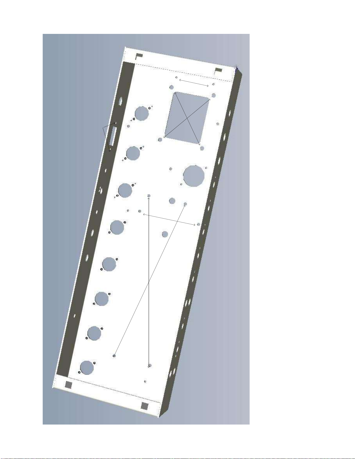
1.
Install the Hardware
There are many nuts bolts etc. required. Here are some guidelines.
Part
Qty
Where to use
4-40 X 5/16”
20-25
Holes are tapped so nuts are not required for tube sockets and
IEC connector.
Use KEPS nuts to hold terminal strip at tube locations. Use with
nuts/lock washer to mount the 5 lug terminal strip and 1-#4
power amp screen resistor terminal strip.
6-32 X 3/8”
3
Mount 3 power ground # 6 chassis lugs with KEPS nut. Mount
Capacitor clamp
6-32 X 3/4”
4
Mount turret board to chassis using stand-offs. Screw though
board –spacer and into chassis tapped hole.
8-32 X 3/8”
1
Mount Mains ground ONLY. Use any additional lock washers
with #8 chassis lug.
8-32 X 3/8”
2
Mount Output trans. With KEPS lock nuts.
8-32 KEPS nuts
7
4 for power transformer (optionally remove Heyboer PT nuts as
supplied); 2 for Output transformer; and 1 for mains ground
bolt.
10-32 X 1-1/4”
4
Mount chassis to cabinet. Use cage nuts in square holes pressed
into chassis.
Trinity Amps TC15 Builder’s Guide. Version 3.5 Page - 17
4-40
(2)
4-40 6-32 X 4
#8
#8 nut
#6
#6(2)
#8
#4
#10 (4)
with cage
nut
4-40 (2)
IEC
4-40
(2) 4-40
(2) 4-40
(2) 4-40
(2) 4-40
(2) 4-40
(2) 4-40
(2)
Trinity Amps TC15 Builder’s Guide. Version 3.5 Page - 18
Tube Sockets - Install all the tube sockets. The chassis is tapped for #4 screws so that nuts are not
required.
Align the #1 pins according to the layout to minimize lead length. RF shield’s are supplied for pre-amp
tubes, V2 to V4. These are mounted on top of the socket and held in place by the #4 screw that holds
the socket in place. The EF86, V1,uses silicon rings to help eliminate microphonics.
Spring retainers are provided for power tubes. These are mounted on top of the socket and are held in
place by the #4 screw that holds the socket in place.
Bear Trap type retainer is provided for the rectifier tube. These are mounted on top of the socket and
are held in place by the #4 screw that holds the socket in place.
Can Capacitor - Install the dual capacitor can cap clamp with #6 X 3/8” bolt and KEPS nut. Loosen
of the clamp screw and insert the dual capacitor JJ 32uF X 32uF can cap into the clamp. Align it so the
2 lugs are parallel to the chassis front. Tighten the clamp screw.
Grommets - Insert 2 - ½” grommets for wire leads passing through the chassis from the output
transformer.
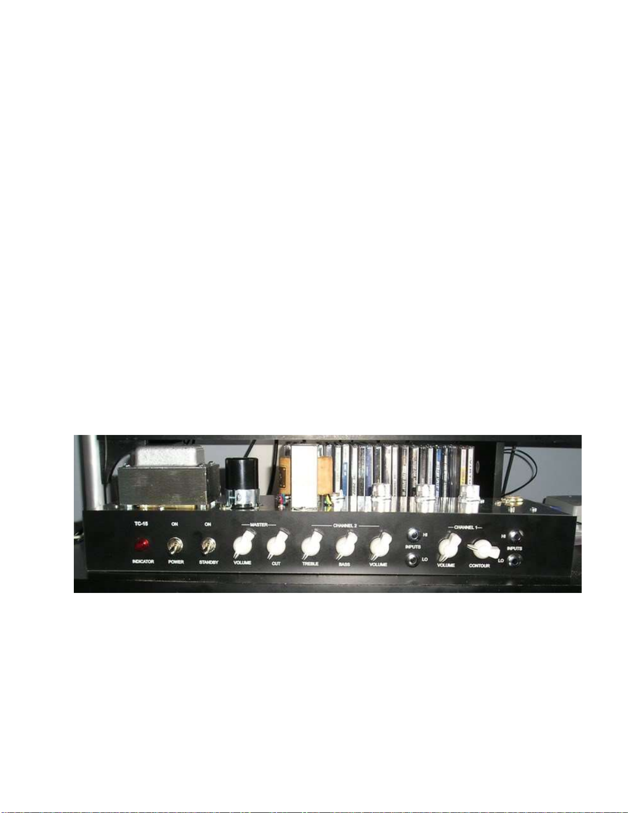
Front Panel - The front panel is installed and held in place by installing the pilot light, power
switches, potentiometers and jacks. Ensure the potentiometers are located in the correct positions
according their values and the layout. The locating tabs on the potentiometers are used to stop them
from rotating and fit into the chassis.
For the input Cliff jacks you will probably need only 1 fibre washer to mount them flush.
Install all parts only finger tight until all parts are fitted, then tighten.
Trinity TC15 Front View
Terminal Strips - Inside the chassis, install the terminal strips (several solder lugs or ‘tags’ attached to
an insulated strip).
5 tag terminal strip (not including 2 ground tags) is used for the power connections;
2 tag terminal strip (not including 1 ground tag) for two 100R screen resistors to the EL84s;
2 tag terminal strip (not including 1 ground tag) for the two 68K grid stopper input resistors on V1;
2 tag terminal strip (not including 1 ground tag) for the two 68K grid stopper input resistors on V2

Trinity Amps TC15 Builder’s Guide. Version 3.5 Page - 19
Terminal strips are mounted using a nut over the socket mounting screw to hold the terminal strip in
place or by using a #4 bolt & KEPS nut as for the two 100R screen resistors to the EL84s.
Ground Lugs - Install the ground lugs:
1 - #8 Mains chassis ground lug using 1 #8 bolt & KEPS nut;
3 - #6 Power chassis ground lugs using 1 #6 bolt & KEPS nut; and
2 - #4 preamp chassis ground lugs using 1 #4 bolt & KEPS nut
Impedance Selector
Install the Impedance Selector paying particular attention to the leads orientation for the correct
impedance selection. Refer to the diagram below for the connections.

Trinity Amps TC15 Builder’s Guide. Version 3.5 Page - 20
Output Jacks - You can install the output jacks, but they may need to be removed to provide good
access to the tube sockets for wiring. You will need to tighten securely to ensure a flush and secure
mount of the jack on the chassis.
IEC Mains Socket - Orient the IEC socket so that the center ground lug points toward the top of
the chassis. Install the IEC socket using 2 - #4 screws , screwed into the chassis which is tapped to
accept them. Nuts are not required.
Fuse Holder - Orient the Fuse holder socket so that the center lug points away from the IEC socket.
Fasten in place with the nut and washer provided.
Table of contents


