10
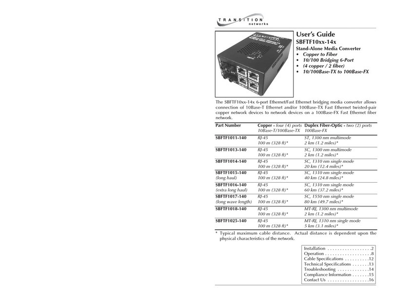
SFEPE10xx-1xx
24-hour Technical Support: 1-800-260-1312 -- International: 00-1-952-941-7600
Technical Specifications
For use with Transition Networks Model SFEPE10xx-1xx or equivalent
Standards IEEE 802.3™
Data Rate 100 Mb/s
Dimensions 7.3" x 4.4” x 1.2" (185mm x 112mm x 30mm)
Weight 1.6 lbs. (730 g) (approximate)
Fuse (DC models only) 6.3 Amp
Power Consumption 45 watts (maximum)
Power Supply - DC 18 to 60 VDC /17 to 30 VRMS (-110 models)
Power Supply - AC 90 to 250 VAC, 50/60 Hz, 45 Watts Max. (-100 models)
Output Voltage 16.8W @ 48VDC; 8.4W @ 24VDC; 4.2W @ 12VDC
Environment Tmra*: 0 to 50°C (32 to 122°F )
Storage Temp: -25 to 85°C (-13 to 185°F )
Humidity: 5 to 95%, non condensing
Altitude: 0 to 10,000 feet
Warranty Lifetime
*Manufacturer’s rated ambient temperature.
NOTE: The information in this user’s guide is subject to change. For the most
up-to-date information on the SFEPE10xx-1xx media converter, view the user’s
guide on-line at: www.transition.com.
Product is certified by the manufacturer to comply with DHHS Rule 21/CFR,
Subchapter J applicable at the date of manufacture.
CAUTION: Visible and invisible laser radiation when open. Do not stare into
beam or view directly with optical instruments.
CAUTION: Use of controls, adjustments or the performance of procedures other
than those specified herein may result in hazardous radiation exposure.
Operation - Continued
MDI Power
MDI power can be set using configuration switches 1 & 2. (See page 3.) The
SFEPE10xx-1xx power delivery capacity is approximately 0.35 A at 48 VDC.
The SFEPE10xx-1xx also has a current sensing feature in accordance with
IEEE802.3af when in IEEE802.3af mode (switch 3 = enabled). If the load
presented to the MDI is less than approximately 10 mA or greater than
approximately 0.4 A*, MDI power is removed from the interface.
(*Including the in-rush current required to charge the PD (Powered Device) load
capacitance.)
Cable Specifications
The physical characteristics must meet or exceed IEEE 802.3™ specifications.
Fiber Cable
Bit Error Rate: <10-9
Single mode fiber (recommended): 9 µm
Multimode fiber (recommended): 62.5/125 µm
Multimode fiber (optional): 100/140, 85/140, 50/125 µm
SFEPE1011-100 (AC-Powered)
SFEPE1011-110 (DC-Powered) 1300 nm multimode
Fiber-optic Transmitter Power: min: -19.0 dBm max: -14.0 dBm
Fiber-optic Receiver Sensitivity: min: -30.0 dBm max: -14.0 dBm
Link Budget: 11.0 dB
SFEPE1013-100 (AC-Powered)
SFEPE1013-110 (DC-Powered) 1300 nm multimode
Fiber-optic Transmitter Power: min: -19.0 dBm max: -14.0 dBm
Fiber-optic Receiver Sensitivity: min: -30.0 dBm max: -14.0 dBm
Link Budget: 11.0 dB
SFEPE1014-100 (AC-Powered)
SFEPE1014-110 (DC-Powered) 1310 nm single mode
Fiber-optic Transmitter Power: min: -15.0 dBm max: -8.0 dBm
Fiber-optic Receiver Sensitivity: min: -31.0 dBm max: -8.0 dBm
Link Budget: 16.0 dB
SFEPE1015-100 (AC-Powered)
SFEPE1015-110 (DC-Powered) 1310 nm single mode
Fiber-optic Transmitter Power: min: -8.0 dBm max: -2.0 dBm
Fiber-optic Receiver Sensitivity: min: -34.0 dBm max: -7.0 dBm
Link Budget: 26.0 dB
The fiber optic transmitters on this device meet Class I Laser safety requirements
per IEC-825/CDRH standards and comply with 21 CFR1040.10 and
21CFR1040.11.
Copper Cable
Category 5: (Minimum Requirement)
Gauge 24 to 22 AWG
Attenuation 22.0 dB /100m @ 100 MHz
• Straight-through OR crossover twisted-pair cable may be used.
• Shielded twisted-pair (STP) OR unshielded Twisted-pair (UTP) may be used.
• Pins 1&2 and 3&6 are the two active pairs in an Ethernet network .
• RJ-45 Pin-out: Pin 1 = TD+, Pin 2 = TD-, Pin 3 = RD+, Pin 6 = RD-
• Use only dedicated wire pairs for the active pins:
(e.g., blue/white & white/blue, orange/white & white/orange, etc.)
• Do not use flat or silver satin wire.
Crossover Cable
1
2
3
6
Straight-Through Cable
Twisted Pair #1
Twisted Pair #1
Twisted Pair #2
Twisted Pair #2
1
2
3
6
1
2
3
6
1
2
3
6
