Technisonic Industries Limited TiL-91-DE/8.33 User manual

VHF/AM BASE STATIONS
MODEL TiL-91-DE/8.33
7 WATT SYSTEM NO. 920607, Opt.8.33 (TBS-150/8.33)
15 WATT SYSTEM NO. 910815, Opt.8.33 (TBS-250/8.33)
25 WATT SYSTEM NO. 910825, Opt.8.33 (TBS-350/8.33)
Installation and
Operating Instructions
Til Document No.
02RE304
Rev. N/C
October, 2002
Technisonic Industries Limited
240 Traders Blvd., Mississauga, Ontario L4Z 1W7 Tel:(905)890-2113 Fax:(905)890-5338
www.til.ca
A Page
WARNING
Do not make physical contact with antenna when transmitter is on. This unit can produce up to 30 watts of
power (depending on configuration) when operated in high power mode.
CAUTION
This unit contains static sensitive devices. Wear a grounded wrist strap and/or conductive gloves when
handling printed circuit boards.
WARRANTY INFORMATION
The Base Stations, Model 91-DE/8.33 series and Model Til 90-6R/8.33 series are under warranty for one
year from date of purchase. Failed units caused by defective parts, or workmanship should be returned to:
Technisonic Industries Limited
240 Traders Blvd.
Mississauga, Amherst, NY, USA
Ontario L4Z 1W7
Tel: (905) 890-2113 Tel: (716) 691-0669
Fax: (905) 890-5338

i
TABLE OF CONTENTS
Paragraph Title Page
iSECTION 1 GENERAL DESCRIPTION
1.1 Introduction ........................................................... 1-1
1.2 Description ........................................................... 1-1
1.2.1 Transceivers - Models Til-91-DE/8.33, Til-90-6R/8.33 ......................... 1-3
1.2.2 Power Supply Modules - Models SPG-007, SPG-015, SPG-025 ................ 1-3
1.2.3 RF Amplifier Modules - Models PA-15, PA-25 ............................... 1-3
1.2.4 DistributionBoard-MarkIISeries ........................................ 1-3
1.2.5 RemoteControlBoards-MarkIISeries .................................... 1-4
1.2.6 Microphone P/N 861902 ................................................ 1-4
1.2.7 Antenna ............................................................. 1-4
1.3 Modes of Operation .................................................... 1-5
1.3.1 Transmit/Receive Modes (Local Mode) .................................... 1-5
1.3.2 Local/RemoteOperation ................................................ 1-5
1.3.3 AC and DC Operation .................................................. 1-6
1.4 TechnicalSummary.................................................... 1-6
SECTION 2 PREPARATION FOR USE AND STORAGE
2.1 Introduction ........................................................... 2-1
2.2 Disassembly/Assembly ................................................. 2-1
2.2.1 Remove/ReplaceCoverAssembly ........................................ 2-1
2.2.2 Remove/Replace Microphone ............................................ 2-1
2.2.3 Remove/ReplaceTransceiver ............................................ 2-2
2.2.4 Remove/Replace Power Supply .......................................... 2-4
2.2.5 Remove/Replace RF Power Amplifier Module ............................... 2-4
2.2.6 Remove/ReplaceDistributionBoard ....................................... 2-5
2.2.7 Remove/ReplaceControlBoard .......................................... 2-5
2.3 RemoteOperationSetUp-LineInterfaceBoards(MarkIISeries)............... 2-6
2.3.1 Two Wire Line Interface board P/N 923051-1 (TLI-203) . . ..................... 2-7
2.3.2 Two Wire Line Interface board P/N 943180-1 (TLI-180) . . ..................... 2-7
2.4 Loudspeaker, Headphone Installation .................................... 2-12
2.4.1 External Loudspeaker ................................................. 2-12
2.4.2 Headset ............................................................ 2-12
2.5 Operational Check .................................................... 2-12
2.6 Storage ............................................................. 2-12

ii
TABLE OF CONTENTS (Continued)
Paragraph Title Page
SECTION 3 TRANSCEIVER SET UP and OPERATING INSTRUCTIONS
Index to Section 3 ...................................................... 3-1
LIST OF TABLES
Table No. Title Page
1-1 BaseStationConfigurations ............................................. 1-1
1-2 Base Station Leading Particulars ......................................... 1-7
2-1 9-Pin "D" Type Remote Connector Functions ............................... 2-6
2-2 9-Pin Positronics Type Remote Connector Functions ......................... 2-7
LIST OF ILLUSTRATIONS
Figure No. Title Page
1-1 BaseStations ......................................................... 1-2
2-1 BaseStationAssembly/Disassembly ...................................... 2-3
2-2 Line Interface/Control Board, P/N 923051-1 (TLI-203) . . . .................... 2-10
2-3 Line Interface/Control Board, P/N 943180-1 (TLI-180) . . . .................... 2-11
(Refer to Index to Section 3, Page 3-1 for Illustrations located in Section 3)

1-2
SECTION 1
GENERAL DESCRIPTION
1.1 INTRODUCTION
Sections 1 and 2 of this publication provide general information on Technisonic VHF/AM Base
Station Systems, Item No.'s TBS-100/150, TBS-200/250 and TBS-300/350. All of the systems
described in this publication include the 8.33kHz spacing option and are designated with an /8.33
suffix. Information for models indicated on the front cover can be found in Section 3.
The /8.33 Base Station Systems consist of a simplex transceiver complete with microphone,
operating over the frequency range of 117.975 to 138.000 MHz with both 8.33 and 25kHz channel
spacing. The Base Station Systems are intended for base station operation in an air traffic
environment. These systems can operate from AC power or external DC power in local and
remote operating modes.
TABLE 1-1 BASE STATION CONFIGURATIONS
System Transceiver Power Supply RF Amplifier Remote
Control
TBS-150/8.33
91-DE/8.33, 7W Base
Station
System No. 920607
w. Option 8.33
Model 91-DE/8.33
P/N 901006
w. Option 8.33
SPG-007
P/N 921020-1
Not Required Optional in
all Units
P/N's
923051-1
943180-1
TBS-250/8.33
91-DE/8.33, 15W
Base Station
System No. 910815
w. Option 8.33
Model 91-DE/8.33
P/N 901006
w. Option 8.33 and
Option 1
SPG-015
P/N 911018-1
PA-15
P/N 912025-1
TBS-350/8.33
91-DE/8.33, 25W
Base Station
System No. 910825
w.Option 8.33
Model 91-DE/8.33
P/N 901006
w. Option 8.33 and
Option 1
SPG-025
P/N 911019-1
PA-25
P/N 922062-1
TBS-100/8.33
90-6R/8.33 7W
Base Station
System No. 920707
w. Option 8.33
Model 90-6R/8.33
P/N 861605
w. Option 8.33
SPG-007
P/N 921020-1
Not Required
TBS-200/8.33
90-6R/8.33, 15W
Base Station
System No.910915
w. Option 8.33
Model 90-6R/8.33
P/N 861605
w. Option 8.33
Option 1
SPG-015
P/N 911018-1
PA-15
P/N 912025-1
TBS-300/8.33
90-6R/8.33, 25W
Base Station
System No. 910925
w. Option 8.33
Model 90-6R/8.33
P/N 861605
w. Option 8.33
Option 1
SPG-025
P/N 911019-1
PA-25
P/N 922062-1
1-2
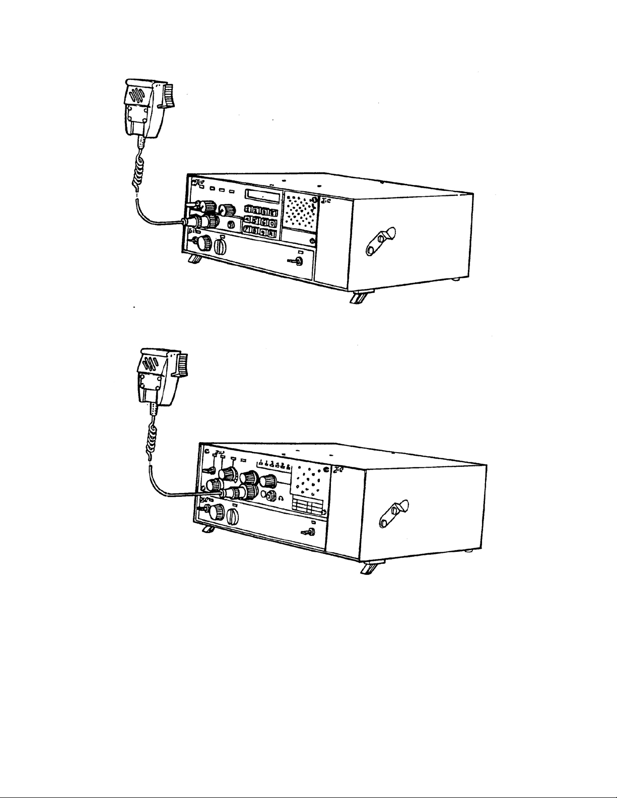
Til-91-DE/8.33 SERIES BASE STATIONS
Til-90-6R/8.33 SERIES BASE STATIONS
Figure 1-1 TBS-Series ase Stations

1-3
1.2 DESCRIPTION
The six base station configurations are based on either the LCD with keypad entry transceiver (TiL
91-DE/8.33) or six channel (TiL 90-6R/8.33) pre-programmable transceiver configured for 7 Watt, 15
Watt or 25 Watt operation. All systems are configured for use of optional Line Interface/Control boards
for remote operation. Each base station consists of a Transceiver, Power Supply Module, RF Amplifier
Module, Microphone and Control Board (optional). Refer to Table 1-1 for system configuration details.
To improve the rejection of interfering signals, dual conversion receiver technology has been
incorporated on the Transmitter/Receiver (Module A1) board used in Technisonic VHF/AM base
stations. The second IF is 455kHz using a ceramic filter, which is immune to high energy
ringing. The dual conversion module also has a second local oscillator, second mixer and
ceramic filter. The first local oscillator is the original VCO.
The dual conversion receiver board, P/N 003494-1 was implemented into TBS and TSC series base
stations starting in January 2001. An option label on the chassis will indicate OPTION 94 if the dual
conversion board is installed. It is possible to retro-fit the dual conversion receiver/transmitter board
into older TSC/TBS series base station employing the single conversion board. Please contact
Technisonic for availability of an exchange board. Note:
If a new A1 Module has been retrofitted the squelch circuit must be aligned for the receiver
squelch to operate correctly.
The dual conversion receiver’s squelch knob must be rotated significantly more clockwise (4
o’clock position) to obtain the same squelch setting (3uV) as a single conversion receiver’s
squelch knob set to the 12 o’clock (straight up) position.
If the dual conversion receiver’s squelch knob is set to the 12 o’clock position, signals with a
level greater than 0.5uV will open the squelch. At most airports this will not be an adequate level
of squelch. Please be aware of this squelch knob adjustment variance when setting and/or
comparing squelch levels of dual conversion vs. single conversion base stations.
1.2.1 Transceivers - Models TiL-91-DE/8.33 and TiL-90-6R/8.33
The basic model of each transceiver is required for the 7 Watt Base Stations. Option 1 indicates that
the basic transceiver has a DC to DC convertor (Module A6) installed to facilitate operation with the
RF Amplifier Module. Refer to Section 3 for specific details on the Transceiver unique to the systems
indicated on the front cover of this document.
1. Transceiver Model TiL-91-DE/8.33, P/N 901006-2 with Option 8.33
Transceiver Model Til-91-DE/8.33, Part Number 901006-2 with Option 8.33, is a microprocessor
controlled, 7 watt VHF/AM transceiver operating over the entire band of 117.975 to 138.000 MHz in
25 or 8.33 kHz steps. The transceiver will store (25) user selected frequency channels in addition to
the resident emergency channel of 121.500 MHz. Frequency Selection, Storage, Recall, Channel
Scan, Search, and Toggle modes are all selected by the 12 key keypad. Current operating frequency
is displayed on a backlit liquid crystal display (LCD).
2. Transceiver Model TiL-90-6R/8.33, P/N 861605-2 with Option 8.33
Transceiver Model 90-6R/8.33, Part Number 861605-2 with Option 8.33, is a 7 watt VHF/AM
transceiver which operates in simplex on six preprogrammable, frequency synthesized channels, with
25 or 8.33 kHz channel spacing in the frequency range 117.975 MHz to 138.000 MHz.
1.2.2 Power Supply Modules - Models SPG-007, SPG-015, SPG-025
The Power Supply Modules provide the DC supply voltage to the Transceiver and Linear Amplifier,
and houses a battery charger which can provide charging and trickle charging to external
rechargeable batteries. Model SPG-007 is for use in the 7 Watt configurations, Model SPG-015 is for
use in the 15 Watt configurations, Model SPG-025 is for use in the 25 Watt configurations.

1-3
1.2.3 RF Amplifier Modules - Models PA-15 and PA-25
The RF Amplifier modules provide 15 Watt (Model PA-15) or 25 Watt (Model PA-25) power output
when the front panel switches are set to High. The RF Amplifiers are fed by the 7 Watt RF output
from the transceiver. An internal mounted RF relay bypasses the RF Amplifier in receive and low
power transmit modes.
1.2.4 Distribution Board
The Distribution Board provides all interconnection between the External DC connector, RF Amplifier
Module, Power Supply/Charger, Remote Control Board (optional), and Transceiver. The optional Line
Interface/Remote Control Boards are mounted on the Distribution Board. The distribution board
provides a 9-pin D connector and RJ-11 (2-wire audio available only) telephone style jack for access
to signals provided by the remote control board. The Line Interface/Remote Control boards indicated
in Table 1-1 are available for use with this distribution board.

1-4
1.2.5 Remote Control Boards - Mark II Series
1. Line Interface Board P/N 923051-1 (TLI-203)
Provides remote control transceiver operation on 2 wire or 4 wire 600 ohm lines. This board can be
configured to key the transmitter using a 2175 Hz* continuous tone (see below), plus/minus DC
Voltages, ground keying and internal or external DC (15 mA) current loop keying. Transmit and
Receive audio is user selectable for two wires or four wires. *Crystals for tone frequencies other than
2175 Hz may be obtained by special order (ie/2380 Hz). An adjustable (30-300 second) Tx time out
function is provided on this board.
2. Line Interface Board P/N 943180-1 (TLI-180)
Provides remote control transceiver operation on 2 wire dedicated 600 ohm lines utilizing the EIA
multi-tone keying format found in the Land Mobile Industry. A high level 2175 tone followed by a 1950
Hz guard tone and then a low level 2175 Hz continuous tone is utilized to key the transceiver. The
943180-1 board can also be jumper strapped for standard aeronautical 2175 Hz continuous tone
operation. DC (15mA) current loop and ground keying is also supported. However this board does
not support 4 wire operation. An adjustable (30-300 second) Tx time out function is provided on this
board.
NOTE P/N 923051-1 is the default board supplied in all units. The EIA multi-tone board
P/N 943180-1 must be special ordered. To determine which remote card your TBS-series
base station has installed, the Configuration label on the back of the chassis should be
consulted.
1.2.6 Microphone P/N 861902-1
An illustration of the Microphone Assembly Part Number 861902-1, is included in Figure 1. The
Assembly P/N 861902-1 consists on microphone P/N 861901-1 and microphone retaining bracket P/N
863905-1. The unit is a rugged hand-held microphone housed in a high impact plastic case. The
dynamic microphone is a noise cancelling type with a two- stage preamplifier, press-to-talk switch,
and a retractable three-core cable terminated by a three-pin, male contacts, connector which mates
with the MIC/PTT connector located on the front panel of the transceiver. The microphone dc supply
for the microphone is supplied by the transceiver. The microphone bracket can be mounted on the
left or right side of the Base Station as required.
1.2.7 Antenna
This unit is designed for use with a 50 ohm impedance antenna (not supplied). A 50 ohm RF N type
connector (BNC available as an option) is provided on the rear of the unit for interfacing with an
antenna.

1-5
1.3 MODES OF OPERATION
Refer to Section 3 for additional operating modes.
1.3.1 Transmit/Receive (Local Mode)
The transceiver may be operated in either of two modes; transmit or receive, as selected by the
Press-to-Talk (PTT) switch on the microphone.
(1) TRANSMIT MODE - When the PTT switch on the microphone is pressed, the transceiver
operates in the transmit mode. The PTT signal line is grounded by the microphone PTT
switch via the microphone lead and the MIC/PTT connector to the transceiver. The Tx ON
amber LED will go ON, indicating that the transmitter is activated.
Transmission will occur on the channel frequency indicated on the front panel. Refer to
Section 3 for transceiver details
(2) RECEIVE MODE - When the PTT switch on the microphone is released, the transceiver
operates in the receive mode. The Tx ON amber LED will go OFF, indicating that the
transmitter is inhibited.
The setting of the SQUELCH CONTROL determines the squelch threshold level. When
the SQUELCH CONTROL is rotated in the counter-clockwise direction, the SQUELCH
INDICATOR green LED will go ON, indicating that the squelch circuit is connecting the
demodulated audio to the VOLUME CONTROL. The setting of the VOLUME CONTROL
determines the audio level produced from the internal speaker. When the VOLUME
CONTROL is adjusted in the clockwise direction, the audio level will increase.
NOTE
When the connector of the external loudspeaker or
head phone is connected to the SPEAKER/PHONE
jack, the internal loudspeaker is disconnected and the
VOLUME CONTROL will control the audio level of the
external loudspeaker or headphone.
1.3.2 Local/Remote Operation
Base Stations which employ the TiL-90-6R/8.33 or TiL-91-DE/ 8.33 transceiver operate in local
and remote modes simultaneously. (The Model TiL-91-DE/8.33 transceiver can be operated in Local
or Remote modes as selected by a front panel switch, upon special request.)
1. LOCAL OPERATION - In local operation, voice audio, and keying (PTT) functions are
routed from the microphone to the transceiver. Receive audio is routed to the internal
loudspeaker.
2. REMOTE OPERATION - In Remote operation, transmit audio, keying (PTT), and receive
audio functions are routed over land lines to the 600 ohm remote input. Internal jumpers
can be set for ±DC, ground transmitter keying, tone keying or current loop keying,
depending on the line interface/remote control board utilized.

1-6
1.3.3 AC and DC Operation
The unit can be operated by external 120 VAC (220 VAC operation available) or external 28
VDC (13.7 VDC for 7W configurations).
1. AC OPERATION - During AC operation, the unit can charge and trickle charge external
batteries via the External DC connector mounted on the rear panel of the Base Station.
Refer Table 1-2 for details.
2. DC OPERATION - The unit can be operated from an external DC supply within the range
of 21.6 Vdc to 30 Vdc for 15 watt and 25 watt configurations and within the range of 11.5 Vdc
to 15.0 Vdc for 7 watt configurations. A DC connector is mounted on the rear of the Base
Station which mates with DC Power Cable P/N 863701-1 (Not Supplied) to facilitate external
DC operation.
The following battery back-up kits are also available for TBS-series base stations:
P/N 989978-1, 24 Volt Battery Back-up Kit (7.2 AH)
For use with 15watt/25watt TBS-series Base Stations. Provides a minimum of 4 hours back-up
for 25 watt unit with 20% Tx and 80% Rx duty cycle. Note: Back-up time for 15 watt unit is
approximately 40% longer.
Kit includes:
qty. (1) p/n 987370-3, DC mating cable with battery connectors.
qty. (2) p/n LCR 12V7.2P, 7.2 amp hour sealed lead acid batteries.
qty. (1) p/n 987246-2, battery interconnect cable.
qty. (1) p/n 968211, battery hook-up instructions.
P/N 989979-1, 12 Volt Battery Back-up Kit (7.2 AH)
For use with 7 watt TBS-series Base Stations. Provides a minimum of 6.5 hours back-up for 7
watt unit with 20% Tx and 80% Rx duty cycle.
Kit includes:
qty. (1) p/n 987370-3, DC mating cable with battery connectors.
qty. (1) p/n LCR 12V7.2P, 7.2 amp hour sealed lead acid battery.
qty. (1) packing log/ instructions.
1.4 TECHNICAL SUMMARY
A summary of electrical, operational, mechanical and physical characteristics of the Base Station are
provided in Tables 1-2 and 3-1.

1-7
TABLE 1-2 BASE STATION SYSTEM LEADING PARTICULARS
POWER REQUIREMENTS:
7 Watt Base Stations
AC Input Voltage/Current ........................... 100 to 132 VAC @ 1.0 Amp
AC Input Voltage/Current (Available) ................. 190 to 250 VAC @ 0.5 Amp
DC Input Voltage/Current ...................... 11.5VDCto15VDC@3.5Amp
15 Watt Base Stations
AC Input Voltage/Current ........................... 100 to 132 VAC @ 1.5 Amp
AC Input Voltage/Current (Available) ................. 190 to 250 VAC @ 0.8 Amp
DC Input Voltage/Current ...................... 21.6VDCto30VDC@4.0Amp
25 Watt Base Stations
AC Input Voltage/Current ........................... 100 to 132 VAC @ 2.0 Amp
AC Input Voltage/Current (Available) ................. 190 to 250 VAC @ 1.0 Amp
DC Input Voltage/Current ...................... 21.6VDCto30VDC@7.5Amp
POWER OUTPUT:
7WattBaseStations .................................................. 5-10Watts
15WattBaseStations(Low/High) ................................... 5-10/10-20Watts
25WattBaseStations(Low/High) ................................... 5-10/20-30Watts
Microphone Compression Range .....................................................35dB
Battery Charger Voltage & Current (15 & 25 watt configurations) ........... 27.5Vdc,3.5AmpsMAX
OPTIONAL REMOTE CONTROL BOARDS - P/N 923051-1
Remote Audio Input ............................... 2or4wire(selectable),balanced600 Ωlines
Remote Tx Timeout ..................................................... 30to300 seconds
Tone Keying:
Impedance ............................................. 600 Ωfloating with respect to ground
TxControlTone..............................................Selectable1800 Hz to 3000 Hz
Tx Tone Input Level .......................................................... 0to-40dBm
Tx Tone Control Response Time ............................................<12milliseconds
DCKeying .....................................................................±48Vdc
Loop Resistance ............................................................. 10KΩMAX
Ground Keying ......................................................... ClosuretoGround
Loop Resistance .............................................................. 4KΩMAX
Remote RX:
Range ......................................... +10dBmto-15dBm(Factorysetto-10dBm)
Impedance ............................................. 600 Ωfloating with respect to ground
RX/TX Interface Signals:
Squelch Signal ................................................ Ground, Open circuit for Mute
TX RF Output Signal ....................................RFON=Ground,RF OFF=Open Circuit
AGC Signal Output ..................................................... Linear 0 to +6 Vdc
Temperature & Humidity:
Operating Temperature Range .......................... -25EC(-13EF) to +55EC(+131EF)
Storage Temperature Range ........................... -55EC(-67EF) to +65EC(+149EF)
RelativeHumidity ........................................................... 100%
Dimensions & Weight:
Width ...................................................... 305 mm (12.0 in) MAX
Height(includingfeet) .......................................... 166 mm (6.5 in) MAX
Depth ..................................................... 274 mm (10.75 in) MAX
Weight ....................................................... 5.5Kg(12lbs)MAX
* Refer to Section 3 for Transmitter and Receiver Leading Particulars

2-1
SECTION 2
PREPARATION FOR USE AND STORAGE
2.1 INTRODUCTION
This section provides the information required for custom configuration of the base station, and
storage. Custom system configuration includes customizing remote control set up, and removal
and replacement of Power Amplifier Module, Transceiver, and Power Supply.
Refer to Section 3 for Channel/Frequency configuration.
Remote set up instructions for Mark II series Line Interface boards P/N's 923060-1, 923051-1,
923051-2 and 923082-1 are provided in paragraph 2.3 of this section.
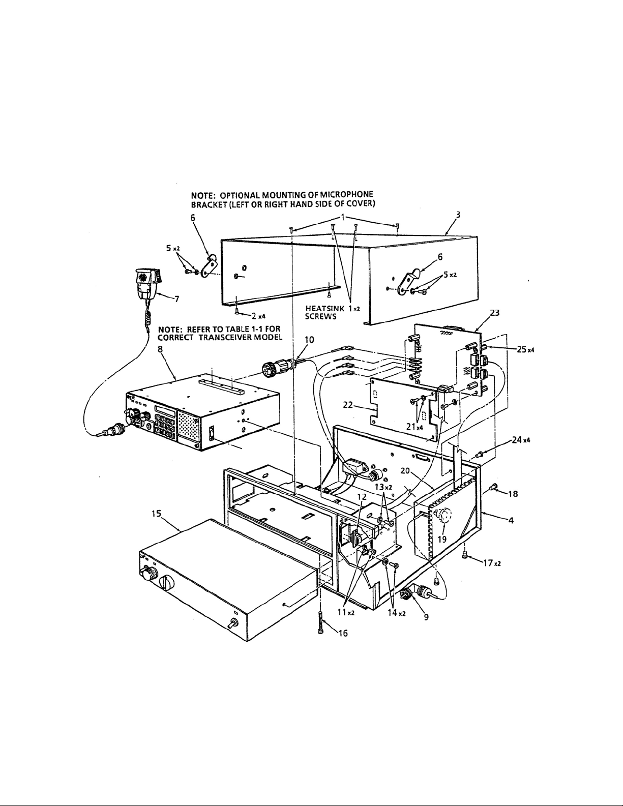
2.2 DISASSEMBLY/ASSEMBLY (Refer to Figure 2-1)
2.2.1 Remove Replace Microphone
REMOVAL
(1) Disconnect microphone (item 7) from front panel of transceiver (item 8). Slide microphone
clear of bracket (item 6).
(2) Remove and Retain two screws (item 5) securing microphone bracket (item 6) to cover
(item 2).
REPLACEMENT
(1) Secure microphone bracket (item 6) to left or right side of cover (item 3) as required
with two screws and two washers (item 5).
(2) Connect microphone (item 7) to front panel connector on transceiver (item 8). Slide
microphone onto bracket (item 6).
2.2.2 Remove/Replace Cover Assembly
NOTE
It is necessary to first remove Microphone Bracket
before removing Cover.
Remove screws securing Heat Sink to cover last, after
removing all other top and bottom screws.

2-2
REMOVAL
(1) Remove and retain two top screws (item 1) securing cover (item 3) to chassis (item 4).
(2) Remove and retain four bottom screws (item 2) securing cover to chassis.
(3) Remove and retain the two heatsink screws.
(4) Slide cover forward or backward to lift cover clear of chassis.
REPLACEMENT
(1) Slide cover (item 3) forward or backward onto chassis (item 4), positioning screw access
holes on cover over chassis threaded inserts.
(2) Secure heatsink to cover with two screws.
(3) Secure cover to chassis with four bottom screws (item 2), then with two top screws
(item 1).
2.2.3 Remove Replace Transceiver
REMOVAL
(1) Remove Cover as described in paragraph 2.2.2.
(2) Disconnect coaxial connector (item 9) from rear of transceiver (item 8).
(3) Disconnect DC connector (item 10) from rear of transceiver.
(4) Remove and retain two screws and two washers (item 11) securing flat cable (item 12)
to transceiver. Disconnect flat cable from transceiver.
(5) Remove and Retain two screws and two washers (item 13) securing transceiver to
chassis bracket.
(6) Slide transceiver toward rear of chassis. Lift transceiver clear of chassis.
REPLACEMENT
(1) Slide transceiver from rear of chassis into top window of Base Station front panel.
(2) Secure transceiver to chassis bracket with two screws and two washers (item 13).
(3) Connect flat cable (item 12) to transceiver. Secure flat cable to transceiver with two
screws and two washers (item 11).
(4) Connect DC connector (item 10) to rear of transceiver.
(5) Connect coaxial connector (item 9) to rear of transceiver.
(6) Replace Cover as described in paragraph 2.2.2.
2-3
Figure 2-1 Base Station Assembly/Disassembly

2-4
2.2.4 Remove Replace Power Supply
REMOVAL
(1) Remove Cover as described in paragraph 2.2.2.
(2) Loosen two screws and two washers (item 14) securing Power Supply (item 15) to
chassis (item 3).
(3) Remove and Retain one screw (item 16) securing Power Supply to bottom of
chassis.
(4) Slide Power Supply forward through window using partially loosened screws (item
14). Remove and retain two screws and two washers and remove Power Supply from
chassis.
REPLACEMENT
(1) Slide Power Supply (item 15) part way into lower front panel window until screw
inserts are visible through chassis bracket holes.
(2) Partially install screws and washers (item 14).
(3) Grasp two screws (item 14) with fingers to position Power Supply into chassis
mounted connectors. Press into position from front panel.
(4) Secure Power Supply to chassis with one screw (item 16) on bottom of chassis.
(5) Tighten screws (item 14)
(6) Replace Cover as described in paragraph 2.2.2.
2.2.5 Remove Replace RF Power Amplifier Module
REMOVAL
CAUTION
Do not adjust nut or shaft (item 19) protruding from
RF Power Amplifier Module. This is a Power
Transistor Mounting Stud.
(1) Remove Cover as described in paragraph 2.2.2.
(2) Disconnect coaxial connector (item 9) from Transceiver (item 8).
(3) Disconnect Flat Cable from Distribution Board (item 23).
(4) Remove and retain two bottom screws (item 17) and one rear screw (item 18) securing
RF (15W) Power Amplifier (item 20) to chassis (item 4). Note: 25W RF Power Amplifier
has four bottom screws (item 17) securing it to the chassis.

2-5
REPLACEMENT
(1) Secure RF Power Amplifier (item 20) to chassis with bottom screws (item 17) and
one rear screw (item 18).
(2) Connect UHF Connector (item 9) to Transceiver and flat cable to distribution board.
(3) Replace Cover as described in paragraph 2.2.2.
2.2.6 Remove Replace Distribution Board
REMOVAL
(1) Remove Cover as described in paragraph 2.2.2. Disconnect flat ribbon cables.
(2) Remove and retain four screws (item 25) securing the distribution and control
boards (item 23,24) to the rear of chassis (item 4).
REPLACEMENT
(1) Secure Distribution Board and Control Board (item 23) to the rear of chassis (item 4)
with four screws (item 25).
(2) Reconnect flat ribbon cables and replace Cover as described in paragraph 2.2.2.
2.2.7 Remove Replace Control Board
REMOVAL
(1) Remove Cover as described in paragraph 2.2.2.
(2) Remove Distribution Board as described in paragraph 2.2.6.
CAUTION
Care must be taken when removing or replacing
Control Board to avoid damage to Distribution Board
Pins.
(3) Remove and retain four screws (item 21) securing Control Board (item 22) "piggy
back" to the Distribution Board (item 23). Remove Control Board from Distribution Board.
REPLACEMENT
(1) Align the two female connectors on the control board with the male connectors on
the Distribution Board using the four mounting holes and standoffs as a guide.
(2) Secure control board "piggy back" to the distribution board (item 23) with four
screws (item 21).
(3) Replace Distribution Board as described in paragraph 2.2.6 and replace Cover as
described in paragraph 2.2.2.

2-6
2.3 REMOTE OPERATION SET UP - Line Interface Boards
The Procedures listed below enable the user to custom configure the unit for external remote
control hardware. Refer to Table 2-1 for connector pin details on Remote Control D Connector
located at rear of Base Station or Table 2-2 for connector pin out on the special order Positronics 9-
pin connector. Position jumpers on Line Interface Board as indicated Figures 2-2 or 2-3 as required.
Verify Remote Control operation in accordance with manufacturers instructions.
TWO WIRE SETUP - In two wire operation, a single balanced 600 ohm pair is provided for
transmit and receive audio. The transmitter can be keyed on the same pair or externally.
FOUR WIRE SETUP - In four wire operation, separate balanced 600 ohm pairs are provided for
transmit and receive audio. The transmitter can be keyed on the Tx audio pair or externally.
DC KEYING - In ± DC keying, a positive voltage between +10 Vdc and +48 Vdc or negative
voltage between -10 Vdc and -48 Vdc will key the transmitter. A DC voltage between -5 Vdc and +5
Vdc will not key the transmitter.
TONE KEYING - In Tone keying a tone of 2175 Hz or 2380 Hz (Optional) can be used to key
the transmitter. Tone sensitivity is adjustable from -40 dBm to 0 dBm.
GROUND KEYING - In Ground Keying the transmitter is keyed by shorting the control point
(landline or External Keying) to chassis ground
CURRENT LOOP KEYING - In Current Loop keying, an internal or external current source (15
mA) is used to key the transmitter
EIA TONE KEYING - The EIA multi-tone keying format is found in the Land Mobile Industry.
A high level 2175 Hz tone followed by a 1950 Hz guard tone then a low level 2175 Hz continuous
tone is utilized to key the transceiver.
TABLE 2-1 9-Pin "D" TYPE CONNECTOR FUNCTIONS
PIN
NO
Two Wire Line Interface Boards
P/N 943180-1
PIN
NO
Four/Two Wire Line Interface Board
P/N 923051-1
8,9
6
2
7
3
1
4,5
2 Wire Remote TX/RX Audio(600Ω)
Ground
RF Indicator
Squelch
External PTT
AGC
Not Connected
8,9
4,5
6
2
7
3
1
4 Wire Remote TX Audio or
2 Wire Rx/Tx Audio (600Ω)
Remote RX Audio Line (600Ω)
Ground
RF Indicator (Optional)
Squelch
External PTT
AGC
NOTE: A modular RJ-11 Jack is also provided on the rear of the chassis (on later units) for quick
connection to the 2 wire, Tx/Rx Audio. The red and green wire connections (centre pins) on the RJ-11 are
connected parallel to pins 8 and 9 on the 9 pin connector. This RJ-11 jack CANNOT be used if the remote
control card is set to 4-wire operation as it does not have the necessary connections.

2-7
TABLE 2-2 9-Pin POSITRONICS TYPE CONNECTOR FUNCTIONS
PIN
NO
Two Wire Line Interface Board
P/N's 943180-1
PIN
NO
Four/Two Wire Line Interface Board
P/N 923051-1
A,B
J
H
F
K
E
D,C
2 Wire Remote TX/RX Audio(600Ω)
Ground
+12 Vdc Output
Squelch
External PTT
Not Connected
Not Connected
A,B
D,C
J
H
F
K
E
4 Wire Remote TX Audio Line or
2 Wire Rx/Tx Audio (600Ω)
4 Wire Remote RX Audio (600Ω)
Ground
+12 Vdc Output
Squelch
External PTT
Not Connected
2.3.1 Two/Four Wire Remote Control Board P/N 923051-1
Provides remote control base station operation on 2 wire or 4 wire, 600 ohm lines. This board can
be configured to key the transmitter using a 2175 Hz tone (2380 Hz upon request), plus/minus DC
Voltages, ground keying and internal or external current loop keying. Transmit and Receive audio
is user selectable for two wires or four wires. Crystals for tone frequencies other than 2175 Hz or
2380 Hz may be obtained by special order.
See Table 2-3 for jumper settings and their functions. See Figure 2-3 for location of jumpers
referred to in the Table 2-3. Pins are numbers increase as you go from top to bottom or left to
right on the connector.
2.3.2 Two Wire Remote Control Board P/N 943180-1
Provides remote control Base Station operation on 2 wire 600 ohm lines. Two wire Line Interface
board with EIA multi-tone, standard 2175Hz continuous tone, DC keying of ground keying over
audio lines. The multi-tone keying format consists of a high level 2175 tone followed by a 1950 Hz
guard tone and then a low level 2175 Hz continuous tone is utilized to key the transceiver. This
board will also support 15mA current loop or ground keying. Refer to Figure 2-4 for jumper
locations to set functions and line level adjustments for this board. Summary of jumper settings
follow. Pins are numbers increase as you go from top to bottom or left to right on the connector.
Set J1 for ST (standard 2175Hz continuous) Tone keying or
for EIA (multi-tone keying format).
Set J2 for Tone keying function ON (left jumper position) or OFF (right jumper position).
Set J3 for Time out timer OFF (left jumper position) or ON (right jumper position).
See Table 2-4 for jumper settings and their functions. See Figure 2-3 for location of jumpers and
left/right orientation referred to in the Table 2-4.

2-8
TABLE 2-3 REMOTE CONTROL BOARD P/N 923051-1 SETTINGS
CONTROL FUNCTION
J1 Jumper Pin 1 and Pin 2 for DC Current Loop Keying
Jumper Pin 2 and Pin 3 for ± DC Keying or Ground Keying.
Note: SW2 must be in position 2 if Pin 2 and Pin 3 are jumpered.
J2
J3
J7
J6
SW1
SW2
Y1,Y2
R7
R22
R25
R44
R10
Jumper Pin 1 and Pin 2 for Ground Keying (Land Line).
Jumper Pin 1 and Pin 4 for ± DC Keying (Land Line).
Jumper Pin 2 and Pin 3 for Ground Keying (Single Key Line).
Jumper Pin 3 and Pin 6 for ± DC Keying (Single Key Line).
Jumper Pin 2 and Pin 5 for No Function.
Jumper Pin 1 and Pin 2 for ± DC or Ground Keying.
Jumper Pin 4 and Pin 5 for Tone Keying.
Note: Both Options may be selected.
Jumper Pin 2 and Pin 3 for No Function.
Jumper Pin 5 and Pin 6 for No Function.
Jumper Pin 1 and Pin 2 to enable Timeout Timer.
Jumper Pin 2 and Pin 3 to disable Timeout Timer.
Jumper Pin 1 and Pin 2 to for Internal Current Loop Keying.
Jumper Pin 2 and Pin 3 to for External Current Loop Keying.
Position 1 Selects 2 Wire Operation.
Position 2 Selects 4 Wire Operation.
Position 1 Selects Normal (Land Line Keying).
Position 2 Selects Local (Single Line Keying).
Determines Keying Tone Frequency.
Sets Tx Audio IN Level (Range -18 dBm to +10 dBm).
Sets Key Tone Level (Range -40 dBm to 0 dBm).
Sets Rx Audio OUT Level (Range -15 dBm to +10 dBm).
Sets Timeout Timer (Range 30 to 300 Seconds).
Sets Receive Audio Output Balance.
Other manuals for TiL-91-DE/8.33
1
This manual suits for next models
3
Table of contents
Other Technisonic Industries Limited Accessories manuals


