Technisonic Industries Limited A710 User manual

ACCESS/A A710/A711
TSO’d High Performance Airborne Audio Systems
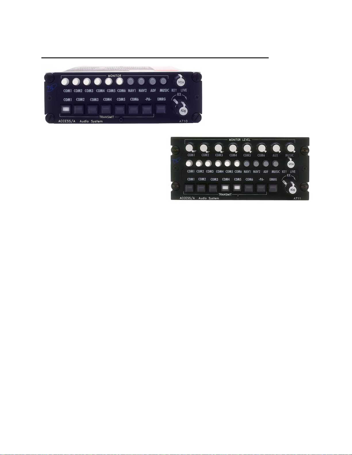
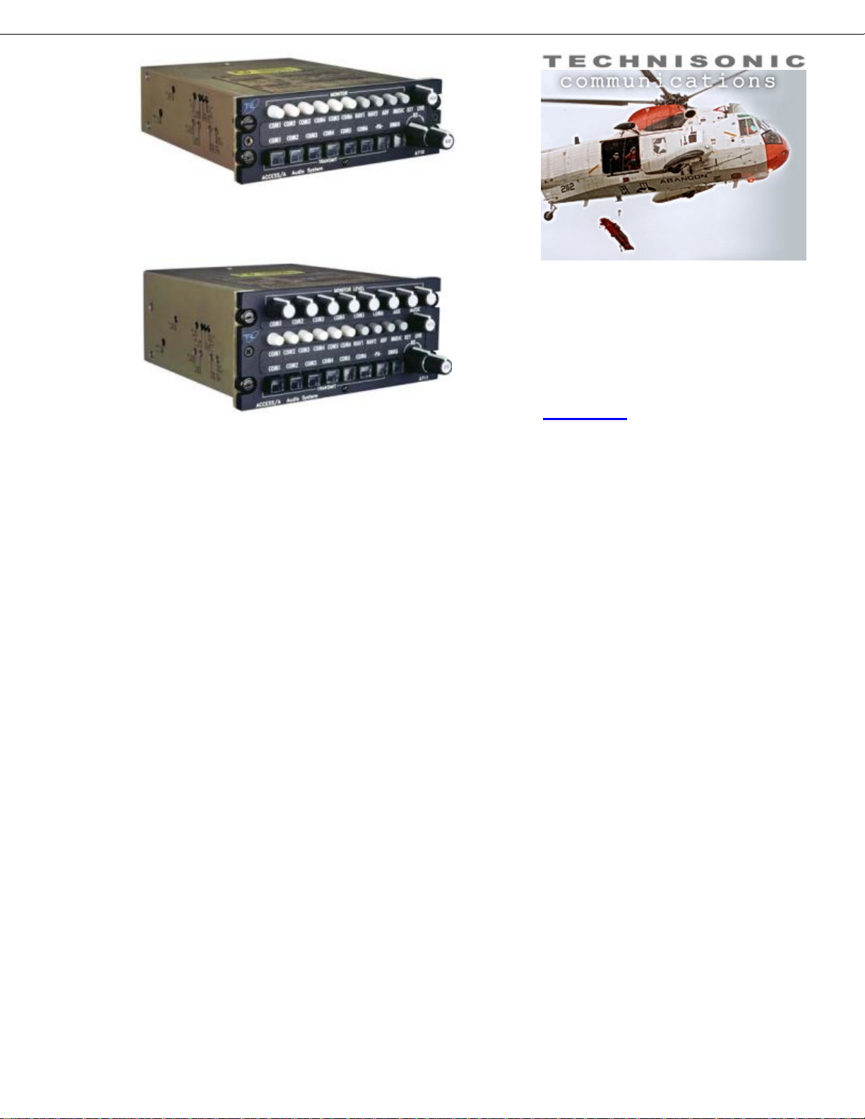
A710
A711
Technisonic High Performance Audio Control Stations
The ACCESS/A system is based on an integrated family of modular, field configurable, panel mounted controls,
coupled with external special function units, which produce a complete airborne communications suite. This flexible
audio system architecture supports extensive transceiver support, multiple ICS busses, alerting, warning and
signaling functions, voice message storage, partitioned crews, and greatly expanded interface capabilities.
ACCESS/A is the physical layer of interconnection and interface between airborne crews and their radio systems, as
well as providing internal intercom, internal and external paging, airframe alerting, music and entertainment
functions. ACCESS/A makes multiple independent crew groups with cross-linking easy to implement for applications
like emergency medevac or forestry aircraft, and delivers high performance solutions for the complex multi-
transceiver communications found in SAR, customs, emergency services and police aircraft.
Compare These Features
Unlike many existing systems, ACCESS/A A710 and A711 controls are designed to be continuously expanded,
relabeled and upgraded in the field, and can be easily re-configured as the aircraft systems are changed or
improved. Up to 10 crew stations, and up to 6 crew members per crew station can be supported within a single
aircraft. Many special modes and functions such as voice alerting, voice storage, NVG compatibility and custom
panel legends can be implemented to provide a very high level of completion center customization, and the modular
construction permits easy “one-shot” solutions for unusual mission specific problems.
Support for all common aircraft headset impedances is standard, including 8, 20, 150, 300 and 600 headsets, as is
“fail-passive” emergency headset and boom microphone operation. Carbon-equivalent, amplified dynamic and
amplified electret microphones are supported, and an optional external module can be installed for un-amplified low
impedance dynamic microphone support.
To address installation concerns and costs, ACCESS/A systems include A740 interconnect bays and modules that
reduce the labor, time and expense of configuring complex ship installations. A740 junction bays, to simplify wiring
and harness fabrication, packaged micro-speakers and user station jack & switch units are all available to solve
these problems quickly and inexpensively.
A710/A711 ACCESS/A stations support both speaker and headset based installations, and can provide internal
paging as well as interfaces to commercially available external paging systems.

General Specifications
Model A710/A711
Power requirements: Aircraft 28 VDC supply (-20% +15 %), 350 mA nominal load.
Meets TSO transient schedule, over voltage and brownout conditions.
28 Volt lighting @ 100 mA, 5 Volt lighting @ 340 mA.
Size and weight: A710 Dzus panel, (5.75” wide x 1.875” high x 6.07” deep). Weight 2.4 lbs.
A711 Dzus panel, (5.75” wide x 2.625” high x 6.07” deep). Weight 3.0 lbs.
Weights shown include optional alerting module.
Environmental: -40C/+70C operating, -55C/+85C survival temperature.
Humidity maximum 96% non condensing.
Shock 12g, any axis
Altitude, to 25,000 feet. (cat. B2)
DO-160C ENV. CAT. (A2B2)-CA(BMN)XXXXXXABBBAXZXXXXXX
Cosmetic: Panel color either Flat Black or Cessna Cadet Flat Gray.
Radio legends are field replaceable Lexan overlays.
System Features: One to six users per control station.
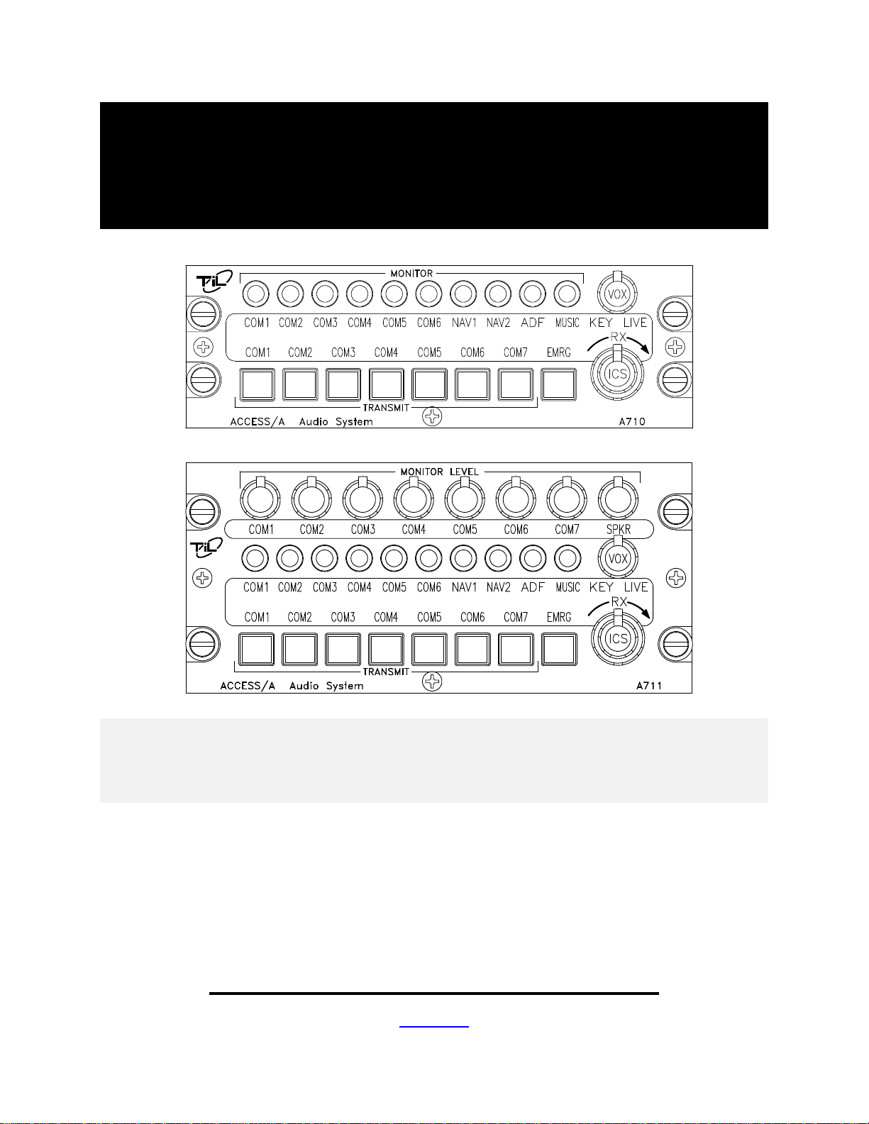
Direct push-button Tx function selection, no rotary switches.
A711 has individual transceiver volume controls, A710 does not.
Supports all headset impedance’s from 8 to 600 ohms.
Optional voice alerting functions with priority.
Optional voice message storage/replay function.
Six transceiver support, plus PA.
Headset and Speaker Outputs.
Soft music muting and stereo music input capability.
VOX, PTT or LIVE ICS modes
Individual Tx status enunciation.
High cross-talk and ground loop rejection.
Split ICS/Rx volume controls.
Emergency Rx/Tx capability, including boom mic support.
Changeable front panel legend system.
Long-life solid state panel lighting system, NVG option.
Configurable ICS loops.
Designed and TSO’d to RTCA C50c audio standard.
Supports multiple transmitter SIMULCAST operation.
Interface Data: At least 500 mW into 150 ohms (per primary user).
At least 1500 mW total into all users (150 ohms).
Distortion less than 2% THD at 1 kHz at total rated output.
Speaker output at least 2.5 Watts into 8 ohms.
Input to input isolation better than -70dB between radio inputs.
Deselected input isolation better than -65 dB.
Hum and noise better than -60dB below 500 mW.
Frequency response within 6dB from 300 Hz to 6000 Hz.
Up to 10 stations per system.
Floating input and output connections.
Ground seeking key and alert lines.
Note: Specifications are subject to change without notice
Technisonic Industries Ltd.
240 Traders Blvd, Mississauga, Ontario L4Z 1W7 CANADA
Ph: 905 890-2113 Fax: 905 890-5338 www.til.ca

Technisonic Industries Ltd. Printed in Canada Copyright 2009, All Rights Reserved
A710
Understanding ACCESS/A Audio
A711
3rd Generation Advanced Analog Systems
Technisonic Industries Ltd.
240 Traders Blvd.
Mississauga, ON Canada
L4Z 1W7
(905) 890-2113
(905) 890-5338
www.til.ca
Rev. 1.1 March, 2009
USERS: One ACCESS/A A710 or A711 station can support up to 6 headset positions in an aircraft, 2 flight
crew (pilot/co-pilot) with full transmit and ICS capability, and 4 passengers with radio monitor and ICS operation.
Passenger operation can also be extended to 5 or 6 positions if required, simply by adding resistors.
INTERCONNECT: Unlike earlier generation designs like the KMA24, AA95, and AMS40 series, the
interconnect in this system is FULLY FLOATING, which means that no audio lines use the airframe ground as
an audio return, thus avoiding noise, cross-talk and unwanted signal contamination. ACCESS/A systems offer as
much as 35dB of improvement in cross-talk (rejection of unwanted signals), a very important consideration in
multi-station systems. Up to 10 A71X-series stations can be used in a single network, and they can be configured
to have multiple ICS (Intercom System) loops.
POWER: Headset output level is a significant problem in many applications, as flight crews are now often
using inefficient helmets and earplugs. ACCESS/A systems offer the highest headset drive currently available in a
panel-mounted system, 1,500mW total. This is considerably more power than earlier generation systems of 100-
500mW. In addition, these systems also have a 2.5W speaker output for radio monitoring when headsets are off.
CUSTOMIZATION: Customization is always a problem in the audio world. Every ship seems to have
some custom issue that needs to be addressed in the audio system. ACCESS/A systems use an easily changed
backlit polycarbonate overlay inset that allows rapid customization of any panel without costly faceplate
changes. Systems already installed can be changed at any time, and custom new installations can be made
quickly with stock units and custom overlays. Faceplate lighting can be 28V or 5V, and NVG compatible lighting is
available. Extensive and convenient cosmetic options are available to the installer at very low cost.
SIMULCAST: Unlike rotary control audio systems, the pushbutton design and high powered mic driver of the
ACCESS/A A710 and A711 controls supports simulcast, allowing multiple radios to be used at once, often an
important operational requirement.
ALERTING: The ship’s audio system serves as the focal point for audible alerting signals passed to the
flight crew. Earlier generation system had limited connections for this, or a few tones that could be generated.
ACCESS/A systems have true voice alerting, with 6 spoken, prioritized messages, and the ability to record
and replay incoming audio. In addition, a direct headset alerting connection is also provided for existing shipboard
systems. Alert messages can also be recorded in any language on a custom basis.

Technisonic Industries Ltd. Printed in Canada Copyright 2009, All Rights Reserved
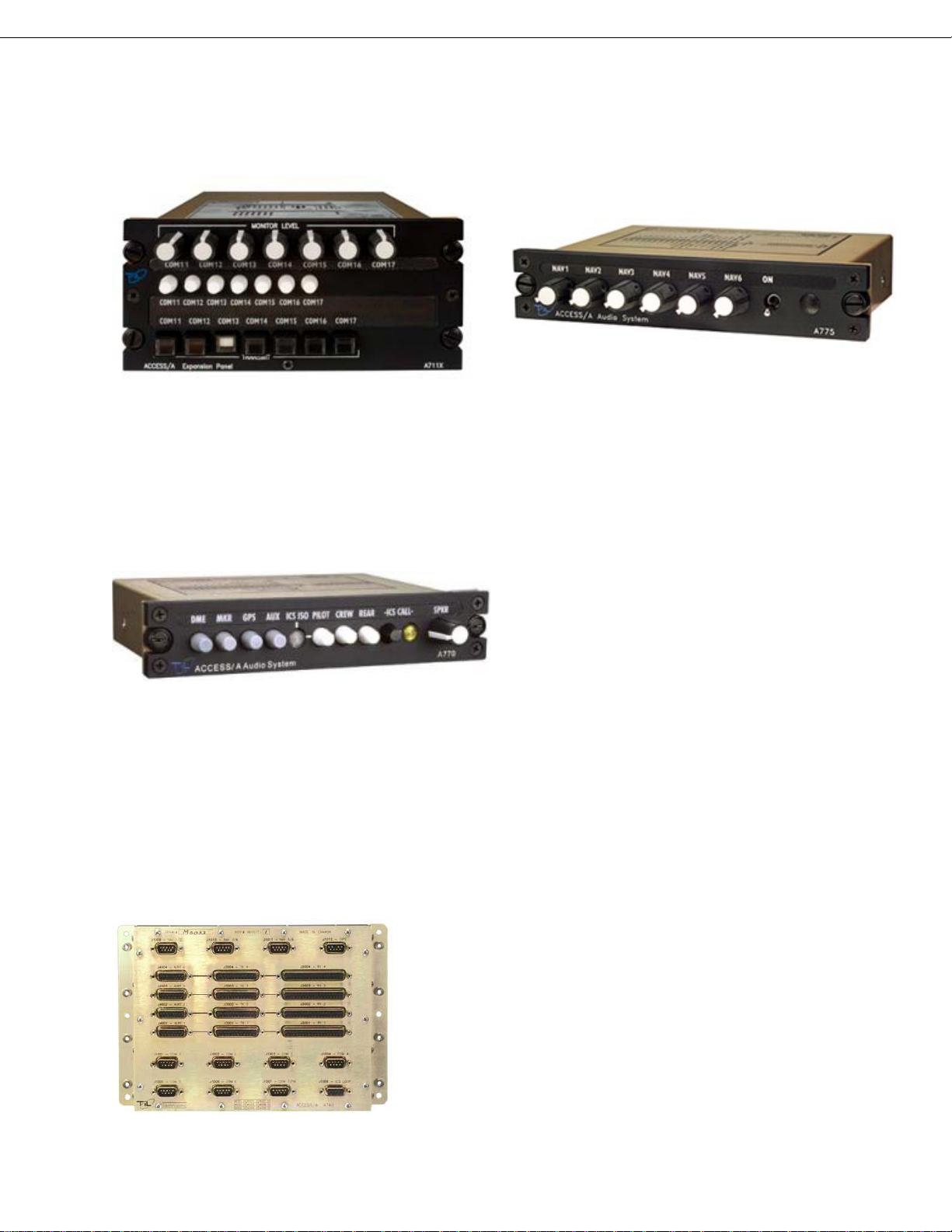
EXPANSION: ACCESS/A controls support 7 TX positions, which can be 6 radios and a PA, or 7
transceivers. Not enough? Need more inputs? Need more variable controls? The ACCESS/A architecture has
special sum node connections that allow inputs and transceivers to be expanded indefinitely either using
ACCESS/A system elements, or your custom external wiring.
A711X Transceiver expansion unit
A775 Receiver Expansion unit
ICS LOOP CONTROL: Often, a ship has to be broken into isolated intercom circuits, such as Medevac
applications, where the medical crew needs to work isolated from the flight crew. Using the ACCESS/A A770
eyebrow unit, additional receiver inputs, and full tie/split ICS loop control can be easily implemented. And in only 3
Dzus holes of panel space!
The A770 provides additional audio inputs,
ICS loop control with calling, and speaker
volume. Many custom variations are possible.
EMERGENCY OPERATION: One huge benefit of analog audio systems is their implicit ability to have
extensive “fail-passive” operation that permits radio operation even if there is serious internal failure, or power is
lost to the box. ACCESS/A systems allow the pilot to have full control of ALL transceivers, and continued cyclic
TX control even in this faulted condition or without power, a unique ACCESS/A feature. This mode can also be
used to provide an isolated radio-only mode for the pilot away from the rest of the users.
INTERCONNECT: Airframe interconnect is always time consuming and irritating, but ACCESS/A systems
can use the A740 interconnect patch bay to speed up harnessing, and provide for very clean cable fabrication
with convenient break and test points. All the connectors in the ACCESS/A system have fully mapped
interconnect that has logical pin assignments and easily followed connections.
The A740 provides a very easy way to manage complex
audio installations of up to 4 stations.

ACCESS/ATM AUDIO CONTROL
SYSTEM
MODELS: A710 & A711
Installation and
Operating Instructions
TiL Document No.
96RE189
Rev. 2.2
July 2009
Technisonic Industries Limited
240 Traders Blvd. E., Mississauga, Ontario L4Z 1W7 Tel:(905)890-2113 Fax:(905)890-5338
www.til.ca

ACCESS/A A710/A711 Installation & Operating Instructions 96RE189
Technisonic Industries ltd. Copyright 1996, 97 BY TiL & SRC LL RIGHTS RESERVED i
REVISIONS
Revision Page Description Date Approved
2.0 Sec. 1 Modified specifications according to TSO tests. DEC 97
Sec. 2 Update to comply wit results of TSO tests. DEC 97
2.1 Sec. 1
Pg.1-6
& 1-7
Modified specifications according to results of
tests for increased Temperature Range and
Altitude.
04 MAY 98
2.2 Sec. 2
Pg. 2-
16
Added clarification for installation kit parts. 08 JULY 09

ACCESS/A A710/A711 Installation & Operating Instructions 96RE189
Technisonic Industries ltd. Copyright 1996, 97 BY TiL & SRC LL RIGHTS RESERVED ii
CAUTION
This unit contains static sensitive devices. Wear a grounded wrist strap and work at a static-safe
workstation when handling internal printed circuit boards.
WARRANTY INFORMATION
The Model A710 Audio Controller is under warranty for one year from date of purchase. Failed units
caused by defective parts or workmanship should be returned for warranty service to:
Technisonic Industries Limited Technisonic Industries Limited
250 Watline Avenue 3840 East Robinson Road, Suite 214
Mississauga, Ontario L4Z 1P4 Amherst, New York 14228
Tel: (905) 890-2113 Tel: (716) 691-0669
Fax: (905) 890-5338
TRADEMARK INFORMATION
ACCESS/A, ACCESS/D, ACCESS/R & ACCESS/F are all trademarks of Technisonic Industries Ltd. and
Sphere Research Corporation. All rights reserved.

ACCESS/A A710/A711 Installation & Operating Instructions 96RE189
Technisonic Industries ltd. Copyright 1996, 97 BY TiL & SRC LL RIGHTS RESERVED iii
TABLE OF CONTENTS
TiL DOCUMENT 96RE189
SECTION 1 GENERAL DESCRIPTION
1.1 Introduction.................................................................................................................. 1-1
1.2 Description .................................................................................................................. 1-1
1.3 Purpose of Equipment................................................................................................. 1-2
1.4 Model Variations.......................................................................................................... 1-2
1.5 Technical Summary..................................................................................................... 1-5
1.6 System Limitations...................................................................................................... 1-6
SECTION 2 INSTALLATION INSTRUCTIONS
2.1 General........................................................................................................................ 2-1
2.2 Equipment Packaging Log .......................................................................................... 2-1
2.3 Wiring Requirements................................................................................................... 2-1
2.4 Audio Panel Installation & Drawings........................................................................... 2-1
2.5 Kit Contents.................................................................................................. 2-16
2.6 Pin Connections and Locations.................................................................... 2-17
2.7 Headphones................................................................................................. 2-21
2.8 Microphones................................................................................................. 2-21
2.9 PTT............................................................................................................... 2-21
2.10 Main Power .................................................................................................. 2-21
2.11 Backlighting Power....................................................................................... 2-22
2.12 Ground ......................................................................................................... 2-22
2.13 Storage...................................................................................................................... 2-22
2.14 Post Installation Adjustment Locations ..................................................................... 2-23
2.15 Post Installation Adjustments.................................................................................... 2-24
SECTION 3 OPERATION
3.1 Front Panel Operator’s Switches & Controls............................................................... 3-1
3.1.1 Intercom Keying Mode & Sensitivity Control.................................................. 3-2
3.1.2 ICS or Intercom Volume Control .................................................................... 3-3
3.1.3 RX or Receive Volume Control ...................................................................... 3-3
3.1.4 RX or Receive Selectors................................................................................ 3-4
3.1.5 TX or Transceiver Selectors........................................................................... 3-4
3.1.6 Emergency Switch Operation & Status LEDs................................................ 3-5
3.1.7 A711 RX Monitor Level Controls.................................................................... 3-6
3.2 Special Signal Considerations .................................................................................... 3-7
3.2.1 Direct Audio Connections............................................................................... 3-7
3.2.2 Sum Node ...................................................................................................... 3-7
3.2.3 Alerting ........................................................................................................... 3-8
3.2.4 Voice Storage Function................................................................................ 3-10
3.2.5 Speaker Audio.............................................................................................. 3-10
3.3 Changing Overlay Lighting & Radio Legends........................................................... 3-11

ACCESS/A A710/A711 Installation & Operating Instructions 96RE189
Technisonic Industries ltd. Copyright 1996, 97 BY TiL & SRC LL RIGHTS RESERVED iv
LIST OF TABLES
1-1 A710 General Specifications.............................................................................................1-4
1-2 A711 General Specifications.............................................................................................1-5
LIST OF ILLUSTRATIONS
1-1 A710 Audio Control - General View..................................................................................1-3
1-2 A711 Audio Control - General View..................................................................................1-4
2-1A A710 Outline Drawing.......................................................................................................2-3
2-1B A711 Outline Drawing.......................................................................................................2-4
2-2 System Installation Drawings- Pilot/Co-Pilot Wiring.........................................................2-5
2-3 System Installation Drawings- COM1-COM4 Wiring .......................................................2-6
2-4 System Installation Drawings- COM5-NAV1 Wiring ........................................................2-7
2-5 System Installation Drawings- NAV2-NAV5 Wiring .........................................................2-8
2-6 System Installation Drawings- NAV6-NAV8/Tape Wiring................................................2-9
2-7 System Installation Drawings- Passenger Wiring ..........................................................2-10
2-8 System Installation Drawings- Alternate Passenger Wiring ..........................................2-11
2-9 System Installation Drawings- Power & Alerting Wiring ................................................2-12
2-10 System Installation Drawings- Direct Input/Special Function Wiring.............................2-13
2-11 System Installation Drawings- Reserved Wiring............................................................2-14
2-11 System Installation Drawings- Special 6-Place Passenger Wiring................................2-15
3-1 Front Panel Operators Switches and Controls.................................................................3-1
3-2 ICS/Intercom Controls.......................................................................................................3-2
3-3 Level/Volume Controls......................................................................................................3-3
3-4 RX & TX Selectors ............................................................................................................3-4
3-5 Status LEDs & Emergency Switch ...................................................................................3-5
3-6 A711 RX Monitor Level Controls ......................................................................................3-6
3-7 Overlay & Legend Insert .................................................................................................3-11
3-8 Removing the Overlay Assembly....................................................................................3-11

710 CCESS/ INST LL TION M NU L COPYRIGHT 1996 BY TiL & SRC LL RIGHTS RESERVED Page 1-1
SECTION 1
GENERAL DESCRIPTION
1.1 INTRODUCTION
This publication provides operating and installation information on the Model A710 and A711,
ACCESS/A Audio Control series manufactured by Technisonic Industries Limited. This unit is
designed to provide high performance cockpit audio control in high noise installations. The unit is
plug and pin compatible with the ACCESS/A family format, to allow fleet wide compatibility with
all ACCESS/A installations. The A710 unit may be directly interchanged with an A711 in the
same harness, but the units are physically different in size, and the A711 has individual volume
controls for the transceiver inputs. Use of either of these boxes in an existing full stereo headset
installation, such as with an A720 or A721, would require the use of a headset output plug
adapter cable, although all other connections would be directly interchangeable.
1.2 DESCRIPTION
This high power audio controller delivers at least 332 mW of audio into 150 ohms at less than 2%
total distortion to the pilot and co-pilot positions simultaneously. It can deliver lower output powers
into 300 and 600 ohm headsets. The pilot’s position may also be internally strapped to interface
with 8-20 ohm headsets at the same power level. Push-button transmit selector switches allow
immediate selection of any of the seven supported aircraft communications transceivers or PA
amplifiers, while additional push-button audio input selector switches allow selection of any or all
of the supported transceivers and Nav aids. ACCESS/A systems have auto-RX switching when
a transmitter is selected, to reduce pilot workload and avoid operational problems.
Both the A711 and A710 have front panel selectable and adjustable VOX, LIVE or KEYED
intercom (ICS) functions. An EMERGENCY mode push-button switch (switch and LED turn red-
orange when activated) provides "straight through" or “fail-passive” transmit and receive audio for
the pilot on the selected communications channel. This switch also provides an implicit pilot
ISOLATION function, and allows the pilot to isolate himself from the co-pilot (and the ICS
system), so that he may access different communications from the other users supported by this
panel (in essence, an emergency link to the selected transceiver only). In the NORMAL position
(switch turns black & LED green), the pilot's audio is provided as selected by all of the panel
controls, and is part of the ICS system. Separate RX and ICS volume controls are provided on
the panel along with an ICS VOX threshold control. These units can also provide ICS support
and boom mic TX support for a complete aircraft crew, including the pilot, co-pilot, and up to 4-6
additional passengers.

ACCESS/A A710/A711 Installation & Operating Instructions
96RE189
Technisonic Industries ltd. Copyright 1996, 97 BY TiL & SRC ALL RIGHTS RESERVED Page 1-2
1.3 PURPOSE OF THE EQUIPMENT
The A710 and A711 ACCESS/A Audio Controls are designed to provide centralized audio
management and control within an airborne communications environment. This includes radio
and transceiver selection, intercom, airframe threat alerting, and crew management. These units
have been packaged to minimize size and weight characteristics and are ideally suited for
helicopter installations, or any other Dzus rail panel location. Both the A710 and A711 meet all of
the current requirements of US Forest Service "contractor furnished avionics" and can be used in
a dual control installation in conjunction with a TiL FM airborne transceiver to comply with all US
Forest Service Contract Requirements. These products are also compliant with TSO-C50c. The
units were tested according to RTCA/DO-214 and RTCA/DO-160C applicable categories with the
exception of the RF Susceptibility Test, which is based upon the requirements of RTCA/DO-
160A, and the Lightning Induced Transient Susceptibility Test which is not called out under
RTCA/DO-170.
1.4 MODEL VARIATION
The A710 and A711 come in two basic lighting configurations. A +28VDC panel lighting version
and a +5VDC panel lighting version. Operationally the two are identical. The color of the solid-
state backlighting is green-yellow, at approximately 565nm wavelength. Panel front color may be
either Cessna Cadet gray or matte black. The default configuration is gray, with 28VDC
backlighting. Units may also be supplied with or without internal voice alerting modules. See the
ACCESS/A price list for model numbers and availability or different versions. The most common
variations are summarized below:
A710 = 961068 - (dash number)
A711 = 961072 - (dash number)
Dash Numbers:
-1 Gray Panel 28VDC Lighting
-2 Black Panel 28VDC Lighting
-3 Gray Panel 28VDC Lighting, includes A851 Voice Alerting
-4 Black Panel 28VDC Lighting, includes A851 Voice Alerting
special order:
-5 Gray Panel 5VDC Lighting
-6 Black Panel 5VDC Lighting
-7 Gray Panel 5VDC Lighting, includes A851 Voice Alerting
-8 Black Panel 5VDC Lighting, includes A851 Voice Alerting

ACCESS/A A710/A711 Installation & Operating Instructions
96RE189
Technisonic Industries ltd. Copyright 1996, 97 BY TiL & SRC ALL RIGHTS RESERVED Page 1-3
Note: shows new case design (relocated Dzus fasteners) effective mid-1997.
Previous release case is identical except for this change (edge Dzus fasteners).
FIGURE 1-1 A710 ACCESS/A AUDIO CONTROLLER - GENERAL VIEW

ACCESS/A A710/A711 Installation & Operating Instructions
96RE189
Technisonic Industries ltd. Copyright 1996, 97 BY TiL & SRC ALL RIGHTS RESERVED Page 1-4
FIGURE 1-2 A711 ACCESS/A AUDIO CONTROLLER - GENERAL VIEW

ACCESS/A A710/A711 Installation & Operating Instructions
96RE189
Technisonic Industries ltd. Copyright 1996, 97 BY TiL & SRC ALL RIGHTS RESERVED Page 1-5
1.5 TECHNICAL SUMMARY
A summary of the relevant electrical, operational, mechanical and physical characteristics of the
control panels are given in Table 1-1 and 1-2, General Specifications.
TABLE 1-1 A710 GENERAL SPECIFICATIONS
MODEL A710 - ACCESS/A Audio Controller:
PHYSICAL CHARACTERISTICS:
Width (max.)........................................................................................................................5.75 inches
Height (max.).....................................................................................................................1.875 inches
Depth...................................................................................................................................6.07 inches
Weight (including alerting)..............................................................................................2.4lbs. (1.09Kg)
Mounting.......................................................................................................Standard Dzus, 4 fasteners
POWER SOURCE REQUIREMENTS:
DC Voltage (MIN, TYPICAL, MAX)......................................................................... 20.0V, 28 V, 32.2V
(System performance will be degraded at upper and lower limits)
DC Current .............................................................................1 A (6 users @ 150 Ω, + speaker @ 8 Ω)
Backlighting Input:
Standard...................................................................................................................28 Vdc @ 50 mA
Optional....................................................................................................................5 Vdc @ 270 mA
TECHNICAL CHARACTERISTICS:
Input Impedance (Normal Mode, any RX input).........................................................1.55 k Ω(typical)
Input Impedance (Emergency Mode, Com1-7 RX Inputs)..........................50 Ω+ Headset Z (typical)
Headset Channel Output Impedance...............................................8 or 80 Ω(depending on settings)
H/S Audio Power Output....................................................at least 332 mW (primary user) into 150 Ω
with 6 headsets (150 Ωeach) connected.
H/S Audio Power Output................................................................ at least 500 mW (pilot) into 8-20 Ω
H/S Audio Power Output...............................................at least 1500 mW (total) into 6 users @150 Ω
Speaker Power Output.......................................................................................at least 2.5 W into 8 Ω
Audio distortion (speaker or H/S)................................less than 2% THD @1kHz at total rated output
Audio Frequency Response (ICS) ................................................within 3 dB from 300 Hz to 6000 Hz
Audio Frequency Response (Rx & NAV) ......................................within 3 dB from 300 Hz to 3000 Hz
Hum and Noise Level...................................................................... better than -60 dB below 500 mW
Input Muting (when mike is keyed)........................................................................................adjustable
Input to Input isolation .................................................................... better than -70 dB between inputs
Deselected input isolation ........................................................................................ better than -65 dB
ENVIRONMENTAL:
Temperature (operating) ....................................................................................-45°C to +70°Celsius
Temperature (survival non-operating) ................................................................-55°C to +85°Celsius
Humidity...............................................................................................................95% Non-condensing
Shock..............................................................................................................................12 g (any axis)
Altitude................................................................................................................................. 25,000 feet

ACCESS/A A710/A711 Installation & Operating Instructions
96RE189
Technisonic Industries ltd. Copyright 1996, 97 BY TiL & SRC ALL RIGHTS RESERVED Page 1-6
TABLE 1-2 A711 GENERAL SPECIFICATIONS
MODEL A711 - ACCESS/A Audio Controller:
PHYSICAL CHARACTERISTICS:
Width (max.)........................................................................................................................5.75 inches
Height (max.).....................................................................................................................2.625 inches
Depth...................................................................................................................................6.07 inches
Weight (including alerting)............................................................................................3.0 lbs. (1.36 Kg)
Mounting.......................................................................................................Standard Dzus, 4 fasteners
POWER SOURCE REQUIREMENTS:
DC Voltage (MIN, TYPICAL, MAX)........................................................................ 20.0V, 28 V, 32.2V
(System performance will be degraded at upper and lower limits)
DC Current ..............................................................................1 A (6 users @150 Ω, + speaker @8 Ω)
Backlighting Input:
Standard...................................................................................................................28 Vdc @ 70 mA
Optional....................................................................................................................5 Vdc @ 370 mA
TECHNICAL CHARACTERISTICS:
Input Impedance (Normal Mode, any RX input)....................................................2K-1.5K Ω(approx.)
Input Impedance (Emergency Mode, Com1-7 RX Inputs)..........................50 Ω+ Headset Z (typical)
Headset Channel Output Impedance...............................................8 or 80 Ω(depending on settings)
H/S Audio Power Output....................................................at least 332 mW (primary user) into 150 Ω
with 6 headsets (150 Ωeach) connected.
H/S Audio Power Output................................................................ at least 500 mW (pilot) into 8-20 Ω
H/S Audio Power Output...............................................at least 1500 mW (total) into 6 users @150 Ω
Speaker Power Output.......................................................................................at least 2.5 W into 8 Ω
Audio distortion (Speaker or H/S) ...............................less than 2% THD @1kHz at total rated output
Audio Frequency Response (ICS) ................................................within 3 dB from 300 Hz to 6000 Hz
Audio Frequency Response (Rx & NAV) ......................................within 3 dB from 300 Hz to 3000 Hz
Hum and Noise Level...................................................................... better than -60 dB below 500 mW
Input Muting (when mike is keyed)........................................................................................adjustable
Input to Input isolation .................................................................... better than -70 dB between inputs
Deselected input isolation ........................................................................................ better than -65 dB
ENVIRONMENTAL:
Temperature (operating) ....................................................................................-45°C to +70°Celsius
Temperature (survival non-operating) ................................................................-55°C to +85°Celsius
Humidity...............................................................................................................95% Non-condensing
Shock..............................................................................................................................12 g (any axis)
Altitude................................................................................................................................. 25,000 feet

ACCESS/A A710/A711 Installation & Operating Instructions
96RE189
Technisonic Industries ltd. Copyright 1996, 97 BY TiL & SRC ALL RIGHTS RESERVED Page 1-7
1.6 SYSTEM LIMITATIONS
A summary of the relevant system limitations is given below.
1.6.1 Power Limitations
With Standard Set-up, which consists of six headsets connected, a power output of not less than
332 mW is delivered per headset (as represented by 150 ohms) provided that the Direct Alert
Input is terminated in not less than 600 ohms and that nominal input voltages are applied
at the applicable channel inputs. Nominal microphone input: 100 mVrms; Nominal
Communications/Navigational Input: 5.5 Vrms.
1.6.2 Frequency Response Limitations
In accordance with the provisions made in RTCA/DO-214 Sections 2.8.1 and 1.5.1 the
communications transmit out and receiver channels (communications and navigational) possess
an effective bandwidth of 300 Hz--3000 Hz with a maximum amplitude variation of 3 dB within the
frequency range.
1.6.3 Crosstalk Limitations
To ensure that the crosstalk specifications are in accordance with the applicable sections of DO-
214, it is essential that 1) manufacturer’s maximum microphone input voltage of -4.7 dBu not
be exceeded in order to avoid jeopardising input to microphone output crosstalk results,
particularly at the low frequency end, 2) in the instance where only two access units are daisy
chained via their ICS tie-lines, a resistor of not greater than 600 ohms must be maintained
across the ICS tie-line in order to avoid jeopardising station to station crosstalk results in Rx
mode at the high frequency end.
The phenomenon of music appearing at the headset of the Second Station Panel (SSP or unit at
which the crosstalk is measured) for station to station crosstalk considerations is a limitation of
the A710/711 and for which crosstalk at high frequencies (6000 Hz and greater) can fall below 65
dB of attenuation. However music for most intents and purposes may be considered an optional
feature, which may be turned off without a negative impact on the essential functioning of the
access units.
Further, valid station to station crosstalk measurements were quoted in respect of a half power
level at the headset at the First Station Panel (FSP or unit from which the crosstalk originates) as
opposed to a half power level at the speaker output of the FSP because it is envisioned in the
latter scenario that the substantial speaker level (which will also necessitate very large signal
levels at the FSP headset) will have an impact on the listener at the SSP whether a crosstalk
signal appears at the SSP listener’s headset or not.
1.6.4 Isolation Limitations

ACCESS/A A710/A711 Installation & Operating Instructions
96RE189
Technisonic Industries ltd. Copyright 1996, 97 BY TiL & SRC ALL RIGHTS RESERVED Page 1-8
When in Pilot Isolation Mode, the pilot microphone for ICS operation is rendered inactive. Consequently,
neither co-pilot nor passengers can receive pilot intercom transmissions while the latter is in Isolation
mode.
1.6.5 Standard Settings Utilised Throughout Testing
Pilot Headset Settings utilised throughout testing was for the standard 150 ohms impedance headset.
The PAL options utilised were applicable to the following configuration: Where Pilot or Co-pilot
transmitted on the UUT ICS communication was possible only in the instance where the signal emanated
from other unit(s) daisy chained to the UUT via the ICS tie-line. In this event the UUT would receive the
ICS transmissions from the other unit(s). It was not possible for the UUT, which transmitted, to export ICS
communication to another unit nor was it possible for intra ICS communication to occur between users
connected to UUT (i.e. Option 1 not implemented).
1.6.6 Transmission Priority
Where Pilot and Co-pilot transmitted simultaneously the Pilot transmissions took precedence over those
of the Co-pilot. Co-pilot transmissions in this case would be rendered inactive.
1.6.7 Induced Signal Susceptibility, RF Susceptibility and RF Emission
The wiring connections called out in the Installation and Operating Instructions, chapter 2, describes
shield terminations for minimum ground loop noise. The test harnesses used for RTCA/DO-160 sections
19, 20, and 21 – Induced Signal Susceptibility, RF Susceptibility, and Emission of RF Energy respectively
- used shield terminations at both ends of the cable. Should RF susceptibility pose a problem in a
particular installation the installer may wish to try terminating shields at both ends of the cable, further, if
this does not produce satisfactory results then double shielding may be required.

ACCESS/A A710/A711 Installation & Operating Instructions 96RE189
Technisonic Industries ltd. Copyright 1996, 97 BY TiL & SRC ALL RIGHTS RESERVED Page 2-1
SECTION 2
INSTALLATION INSTRUCTIONS
2.1 GENERAL
This section contains information and instructions for the correct installation of the A710 and
A711, ACCESS/A Audio Controllers.
Make certain that the unit is correctly operating in accordance with the equipment user's
requirements and manufacturer’s specifications, prior to releasing the equipment for service.
2.2 EQUIPMENT PACKING LOG
Unpack the equipment and check for any damage that may have occurred during transit. Save
the original shipping container for returns due to damage or warranty claims. Check that each
item on the packing slip has been shipped in the container. Verify that the equipment's
backlighting configuration is the same as that required.
2.3 WIRING REQUIREMENTS
Airframe wiring should be single conductor in accordance with MIL-W-22759 or multi-conductor in
accordance with MIL-C-27500 or Raychem 44 (81044) or 55 single or multi-conductor and
shielded wire. Heatshrink solder sleeves (such as Raychem or equivalent) should be utilized for
shield termination.
All Microphone audio input and output line connections should be made with 2 conductor/twisted
pair shielded cables as illustrated. Receiver audio input lines should also be 2 conductor twisted
pair shielded cables. The power and ground lines should be a minimum of #22 AWG (#20
preferred). Keying and all audio lines may be #24 AWG or larger.
CAUTIONS:
DO NOT bundle any low level audio lines with RF coaxial cables, 60 Hz or 400Hz AC
inverter, motor, pump or blower wiring, which can cause noise coupling between the various
systems, especially during RF transmission or pump/blower mechanical operation. Maintain as
much distance as possible from these types of wire bundles.
Note that there is really no effective field-installable shielding for magnetic coupling (which
occurs at high currents), and the only suitable prevention for this type of interference is distance
between the interfering lines. Shielded wiring is effective only for electrostatic coupling, or
voltage driven interference.
2.4 ACCESS/A AUDIO PANEL INSTALLATION
The A710 and A711 ACCESS/A Audio Controls are designed to be Dzus mounted and should
be installed in conjunction with an IN-A710 installation connector kit. See Figure 2-1 for an
outline drawing of the units with dimensions, to facilitate the installation.

ACCESS/A A710/A711 Installation & Operating Instructions 96RE189
Technisonic Industries ltd. Copyright 1996, 97 BY TiL & SRC ALL RIGHTS RESERVED Page 2-2
CABLE CLEARANCE:
Allow at least 2.5” of additional rear clearance for mating connectors and hoods (side routing),
or 3.0” (back routing). Cables should be long enough to permit the unit to be removed from the
panel, and the connectors to be easily disengaged. DO NOT dress or strap the mating cables so
that front removal is impossible, or the unit cannot be removed for service or adjustment in the
field.
ALERT OPERATION:
Voice alerting can be supplied with this unit from the factory (addition of an A850, A851 or A852
module and resulting dash number change), or it can be added in the field. Field installation must
be done at a fully equipped service bench, and requires a system functional test & re-
certification.
PANEL MODIFICATIONS:
Modified panel legends, panel lighting, NVG compatibility, or overlay colors are also
possible, please see the price list for a full summary of options and part numbers. Overlays and
legends may be easily changed at low cost in the field with no special tools or service facilities
required.
SHIELD GROUNDS:
Convenient shield ground connections are provided at each connector for the indicated input
signal shield drains, and will give the shortest possible return for these lines. These shield lines
may be daisy chained together, and a single wire from each cable brought out to the connector
pin .
INTERNAL OPTIONS:
All configurable and variable options of the A710 and A711 (pilot H/S impedance, muting logic,
included speaker audio lines, etc.) can be set or changed simply by altering internal jumpers, but
these changes require opening the unit for access to the required connections.
DRAWINGS:
A full ACCESS/A (mono) system installation example is given in the multi-page sections of
Figure 2-x. These installation and mechanical drawings are available as AutoCAD files
(“DWG”/R12 format, Windows Metafile “WMF” or “DXF” format) free of charge to authorized TiL
dealers and completion centers.

ACCESS/A A710/A711 Installation & Operating Instructions 96RE189
Technisonic Industries ltd. Copyright 1996, 97 BY TiL & SRC ALL RIGHTS RESERVED Page 2-3
FIGURE 2-1A Outline Drawing for Model A710 ACCESS/A Audio Controller
Other manuals for A710
1
This manual suits for next models
1
Table of contents
Other Technisonic Industries Limited Recording Equipment manuals