TECHNO-AC Success AG-309.15 N User manual


DEVELOPMENT, MANUFACTURING AND SUPPLY OF INSTRUMENTATION
2
Table Page of Contents
Introduction..............................................................................................3
1. Appearnce of Receiver ........................................................................... 4
2. Receiver menu descripti on.....................................................................5
2.1 Receiver switching on and menu call...............................................5
2.2 The general view of the menu screen......................................... .... 5
2.3 Menu parameter selection.............................................................5
3. Startof work........................................................................................... 11
4. Search of cables in the mode «Route»....................................................12
4.1. Cable location in the passive mode..................................................... 12
4.2. Search of a communication and measurement of its burial depth..........12
4.3. Hot keys for work in the «Route» mode.................................................14
4.4 Cable route location in the active mode.................................................14
5. Search of communications in the mode «Graphic».................................18
5.1. Setting of the receiver for work in the «Graphic» mode.......................... 18
5.2. «Hot» keys for work in the «Graphic» mode ...........................................20
5.3. Search of communications in the mode «Graphic» ................................21
6. Search of the utilities in the mode « Graphic+».......................................22
6.1. Setting of the receiver for work in the «Graphic+» mode........................ 22
6.2. Search of communications in the mode «Graphic+».............................. 22
7. Perfoming the cable location in the mode «Minimum maximum».......... 24
8. Performing cable route location in the mode «2 frequencies» ............... 25
9. The work mode «Cable selection from a bunch» .................................... 27
10. Mode «Search of defects» using external sensors .............................. 31
Appendix 1.................................................................................... 37
Appendix 2.................................................................................... 38
11. Transmitter AG-105..............................................................................43
12. Working with the device....................................................................... 50
12.1 Preparatory activities ......................................................................... 50
12.2 Settings............................................................................................. 53
12.3 Clips.................................................................................................. 53
12.4 Internal transmitting inductor «In» ........................................................ 54
12.5 External induction transmitting antenna................................................ 54
12.6 Transmitting induction “clamp”............................................................ 55
12.7 External power sources ...................................................................... 55
12.8 Electromagnetic compatibility............................................................. 56
12.9 Ingress protection rating..................................................................... 56
Transmitter AG-105 Technical specifications............................................ 57
Appendix C Transmitter AG-105 Indication................................................ 59

DEVELOPMENT, MANUFACTURING AND SUPPLY OF INSTRUMENTATION
3
Introduction
This Operation manual contains description of the cable route locator AP-019.1, its working
modes, and information necessary for its proper use. АP-019.1 (hereinafter «the receiver») can be
used and a individually, and with the transmitter. The receiver works at the networks frequencies
50(60) Hz, 100(120) Hz, and with route locating transmitters at frequencies 512Hz, 1024 Hz, 8192
Hz, 32768 Hz («33 kHz»).
CBI-309.15N is used for:
-Detection of cables and metal pipelines underground up to 10 m;
-Direct digital measurement of the depth up to 10 m;
-Indication of the deviation from the utility axis in the mode “ROUTE”;
-Measurement of the current in the cable;
-Survey the ground before the excavation works;
-Distance of tracing from the place of transmitter connection is up to 3 km.
Operation with optional equipment:
- Superimposed frame “NR -117”
- Sensors DKI and DODK.
Searching of cable faults at shorting of its armoring to the ground -Searching of outer
insulation defects of metal pipelines (water, gas) at trenchless laying.
- Inductive clamps KI-110
- Identification of the cable, the function “selection the cable from a bunch”
- Non-contact connection to the pipelines or to the cable lines
Intended use
-Power
-Public utilities
-Oil and gas industry
-Geodesy
-Communication
-Construction
-Other industries
Operation conditions
-Ambient temperature, °С ..........................................from -20С to +60
-Relative humidity, % .................................................up to 85 at t=35 °С
-Pressure, kPa,.............................................................84 to 106
-Device protection class............................................. IP 54
Receiver working principle
The receiver working principle is based on the analysis of the electromagnetic field, created
by the alternative current flowing through communications. The electrical signals induced in
the receiver sensors are amplified, filtered, processed by the processor and displayed on the
graphical display in the form of the communication position line, linear scale, and the graphic of
the signal level change, digital value of the signal level amplification coefficient, distance to the
communication axis, the value of the current flowing through it, and other parameters.
DEVELOPMENT, MANUFACTURING AND SUPPLY OF INSTRUMENTATION
4
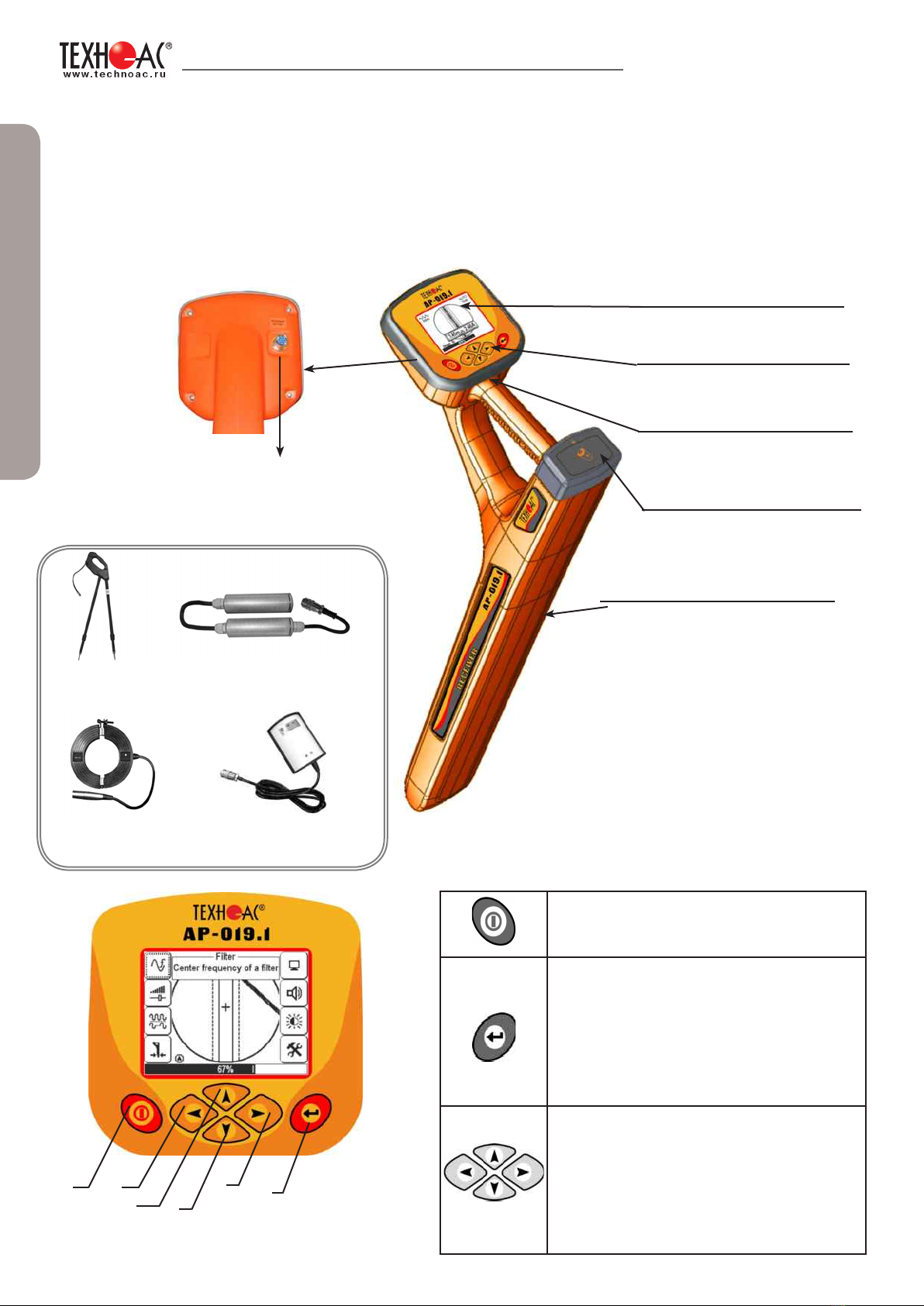
1. Appearance, AP-019.1 receiver controls
AP-019.1 receiver is made in the solid cast IP54 body, to the battery compartment the body
provides the protection IP68, the device can be splitted in three components: the face panel with
controls and displays, battery compartment and bottom part with the antenna block. On the back
side of the face panel, there are two slots for connection of external sensors.
A slot for connection of the
external sensors
A graphical display with
the lighting
Сonnection of external sensors.
DODK-117
A sensor-determiner of the
communication defects
DKI-117
Insulation quality
control sensor
NR-117
Superimposed
frame
KI-110
Inductive clamps
Face panel, controls
«Power» button (1)
Switching on/off the receiver
«Enter» button (6)
- calls out a menu,
- enters into the editing mode of the
selected menu option,
- exit for the editing mode saving
selected parameters.
Buttons «Up» (3), «Down» (4), «Right»
(5), «Left» (2).
- selection of the menu option (icon),
- selection or changing the parameter
inside the menu,
- operative change in the parameters
1 2
34
56
A module for omnidirected
antenna
Battery compartment for
four batteries «type C»
Built-in sound transmitter
Six-button
keyboard
Reference information

DEVELOPMENT, MANUFACTURING AND SUPPLY OF INSTRUMENTATION
5
To open
the menu
press
«Enter».
Menu option
selection is
performed with
buttons
«Up», «Down»,
«Right», «Left».
The menu will appear on the screen. Active "icon" is flashing and
highlighted by dotted line
to change or
view the menu
item
The changed value
is immediately
applied.
To exit the menu to the
general menu or
transfer to the set mode
with the closing of the
menu, you should press
the button «Enter».
If you wait for several
seconds, menu icons will
disappear.
In the upper part of the
indicator the parameter editing
panel will open.
If you don’t press any buttons for a period of time, the menu will disappear automatically.
The length os this period is set in the corresponding menu option (see Table 1. p.6)
2. Receiver menu description
2.1 Receiver switching on and menu call
To switch on
the receiver
press the
button
«Power»
Press «Enter»
button to
open the
Menu
2.2 The general view of the menu screen
Reference information
menu option name
brief menu option
description
2.3 Menu parameter selection
The selected menu
option is highlighted with
the dotted line, flashes
with light/dark
DEVELOPMENT, MANUFACTURING AND SUPPLY OF INSTRUMENTATION
6
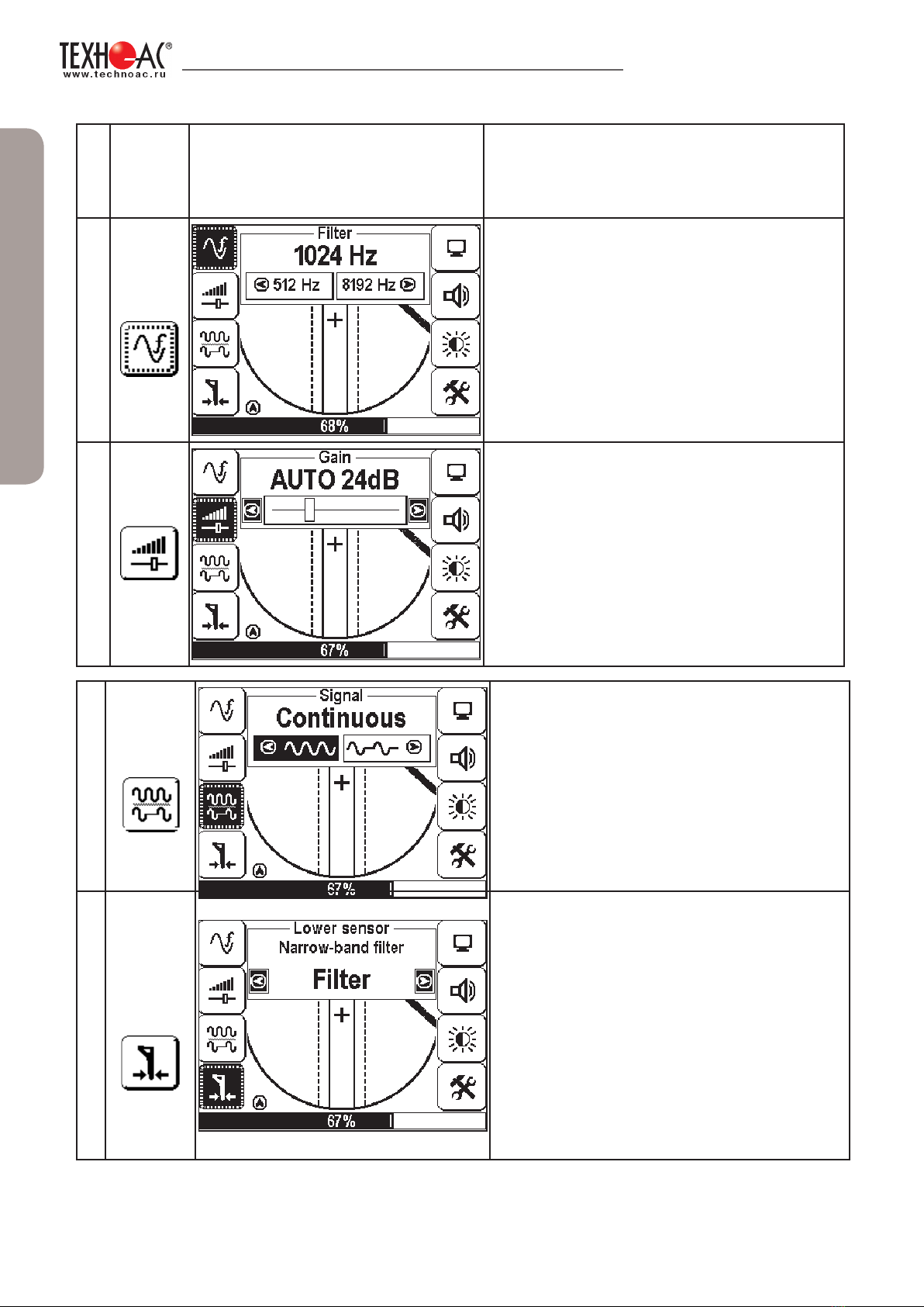
thirteen items of menu contain parameters of setting, which are opened in the panel located in the upper part of
the indicator.
№
Item
of the
menu Display image Parameter description
1
Filter The working frequency of the receiver
It is selected from the set: 50(60) Hz,
100(120) Hz, 512 Hz, 1024 Hz, 8192 Hz
32768 Hz.
2
Gain
The amplification coefficient of the scaling
amplifier can be changed from 0 dB to 80 dB
with 2 dB step.
The optimum coefficient of amplification can
be selected:
- manually,
-semiautomatically (by a command),
-automatically depending on the regime of
the analysis and signal representation.
Table 1
3
Signal The type of signal received can be
«Continuous» or «Impulse».
4
Advanced
bottom
sensor
setting
This option has several settings affecting
the efficiency og bottom sensor.
- «Filter» (all filters enabled)
- «WS» (all fillter disabled, sensor receives
all frequencies below 8kHz).
- «Radio» sensor receives all frequencies
over 8kHz.
‘Filter’ setting is used only in ‘Route mode’,
other settings are used in ‘Graphic’ mode.
Reference information

DEVELOPMENT, MANUFACTURING AND SUPPLY OF INSTRUMENTATION
7
5
Base
Mode Set of modes:
- «Route» (2D display of the location of the
route cable;
6
Base
Mode
- «Graphic» (visually represents the changes
of signal level of surveyed cable);
7
Advanced
Mode Advanced mode:
- «Graphic+» (this mode combines two
previous modes and allows to locate two cables
simultaneously: one on 50Hz, and the other on
freqency set by transmitter.z);
Reference information

DEVELOPMENT, MANUFACTURING AND SUPPLY OF INSTRUMENTATION
8
8
Advanced
Modes
Advanced of mode:
- «minimum maximum» (graph representation
of minimum and maximum signals)
9
Advanced
Modes
Advanced mode:
«2 frequency» (simultaneous operation in two
frequencies, also know as frend-or-foe mode).
10
Sound
Switching on / switching off of tsound
notifications the created by the built-in speaker.
11
Backlight It sets the brightness of the LED display.
It has following values::
- 0%
- 50%
- 100%
Reference information

DEVELOPMENT, MANUFACTURING AND SUPPLY OF INSTRUMENTATION
9
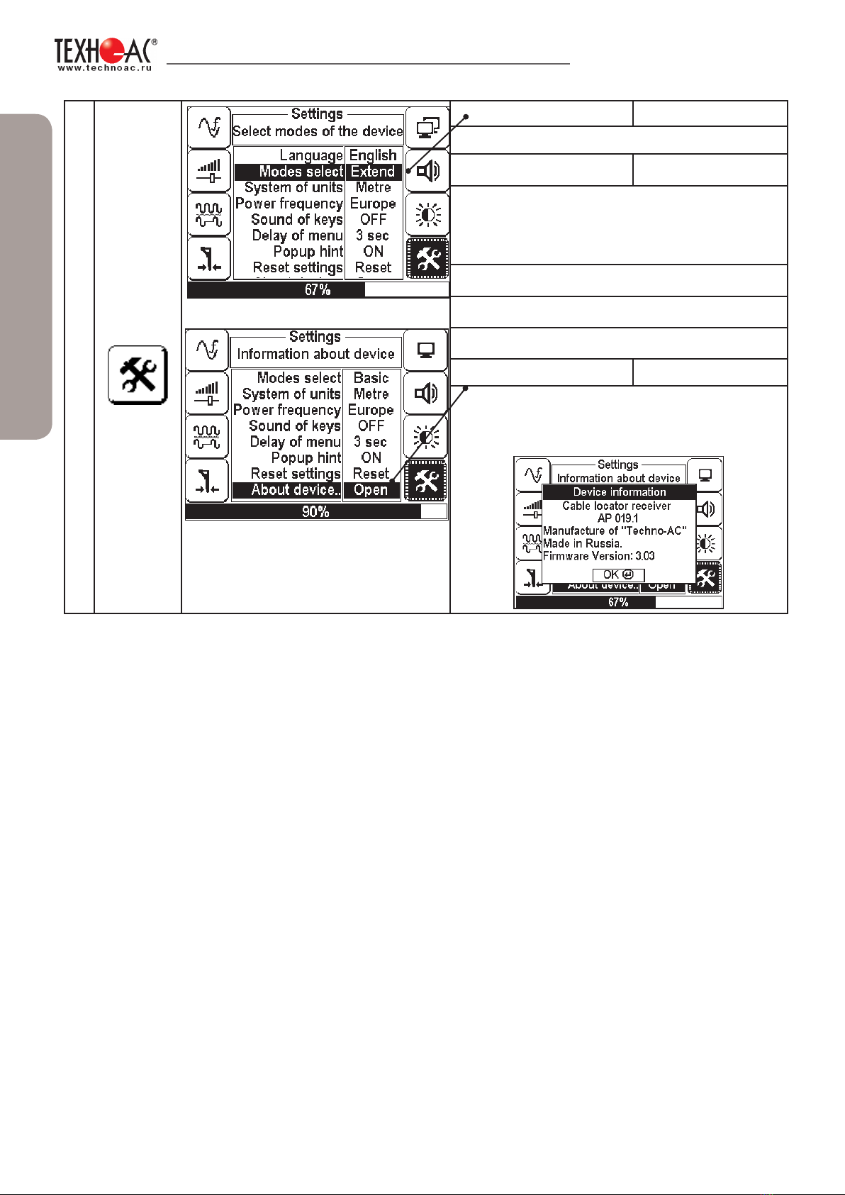
13
Settings
Sound of keys <ON/OFF>
Disables keys sound
Delay of menu <1 sec/2 sec/ 3 sec/ 4
sec/5 sec>
Time-out before closing the menu when no
buttons are pressed.
—• Popup
hints <ON/OFF>
Disables pop-ups with useful hints.
• Reset
osettings <Reset>
Resets the receiver to factory settings
12
Settings
This menu is opened in the main field of an
indicator
Language <Russian/English>
Locale of the device
Measurement
system <Meter/Foot>
Measurement system: metrical or imperial
Network
frequency <Europe/USA>
The network frequency for passive search:
«Europe» (50 и 100 Hz) / «USA» (60 and 120
Hz).
Reference information
DEVELOPMENT, MANUFACTURING AND SUPPLY OF INSTRUMENTATION
10
16
Settings
Modes select basic / advanced
Available modes select
Basic Advanced
About device
about device <Open>
Information about the device will pop-up in a
dialog window.
Reference information

DEVELOPMENT, MANUFACTURING AND SUPPLY OF INSTRUMENTATION
11
With factory settings enabled you can perform the cable location with network frequency
50 Hz in without transmitter.
3. Start of work
The screen
saver will
appear on the
screen with the
indication of
the Firmware
version ,
manufacturer
and device
name
The screensaver
is followed by
voltage and
battery charge
indicator..
Then the receiver will automatically enter
into the mode «Route» in 5 seconds. At the
first switching the factory settings are set by
default. The filter frequency is 50 Hz.
Before start of work, you should install the batteries into the corresponding compartment of
the receiver in the following sequence:
Pull out the ring on the
receiver handle
Battery compartment will
unsnap
Remove the battery
compartment from the
receiver body
Install four new elements into
the battery compartment of the
device, minding polarity
Install the battery compartment
into the body until it snaps.
Note
To switch on the receiver press the button «Power»
Receiver switching on
The description of factory settings can
be found in the menu «Parameters». You
can go back to factory settings by selecting
the parameter «reset settings»
DEVELOPMENT, MANUFACTURING AND SUPPLY OF INSTRUMENTATION
12
4. Search of cables in the mode «Route»
The Route mode is the main mode for route location of various communications (cables, pipelines)
at all frequencies supported by the receiver, both a «passive» cable route location, and at the «active»
(with the use of the route locating generator). In the passive mode the cable location is carried out at
frequencies 50(60)100(120)Hz, in the active mode -512,1024, 8192, 32768 Hz.
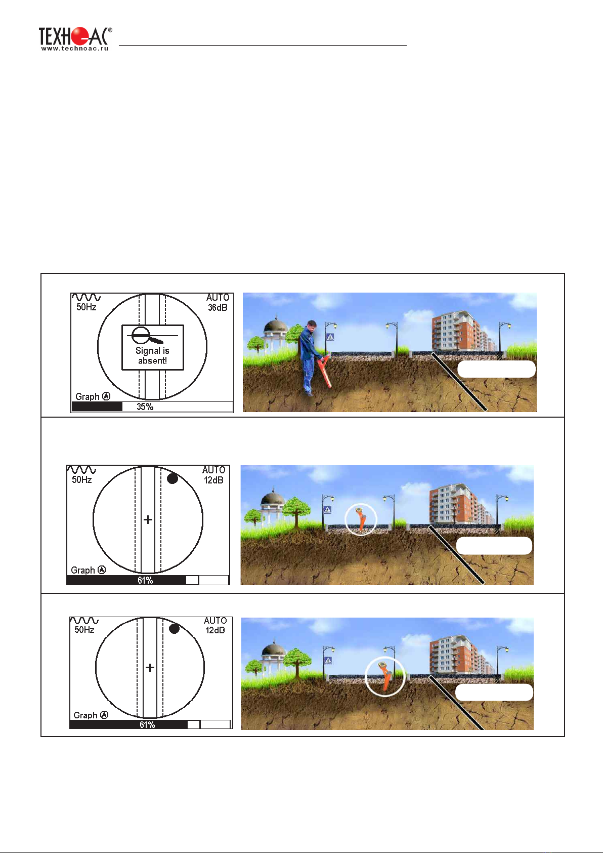
4.1. Cable location in the passive mode
This mode is used to search and locate a route of power cables under voltage with the frequency
50(60) Hz and other communications with the induced signal in frequency 50(60) Hz. The filter set
on the receiver - 50(60) Hz. The external generator is not used.
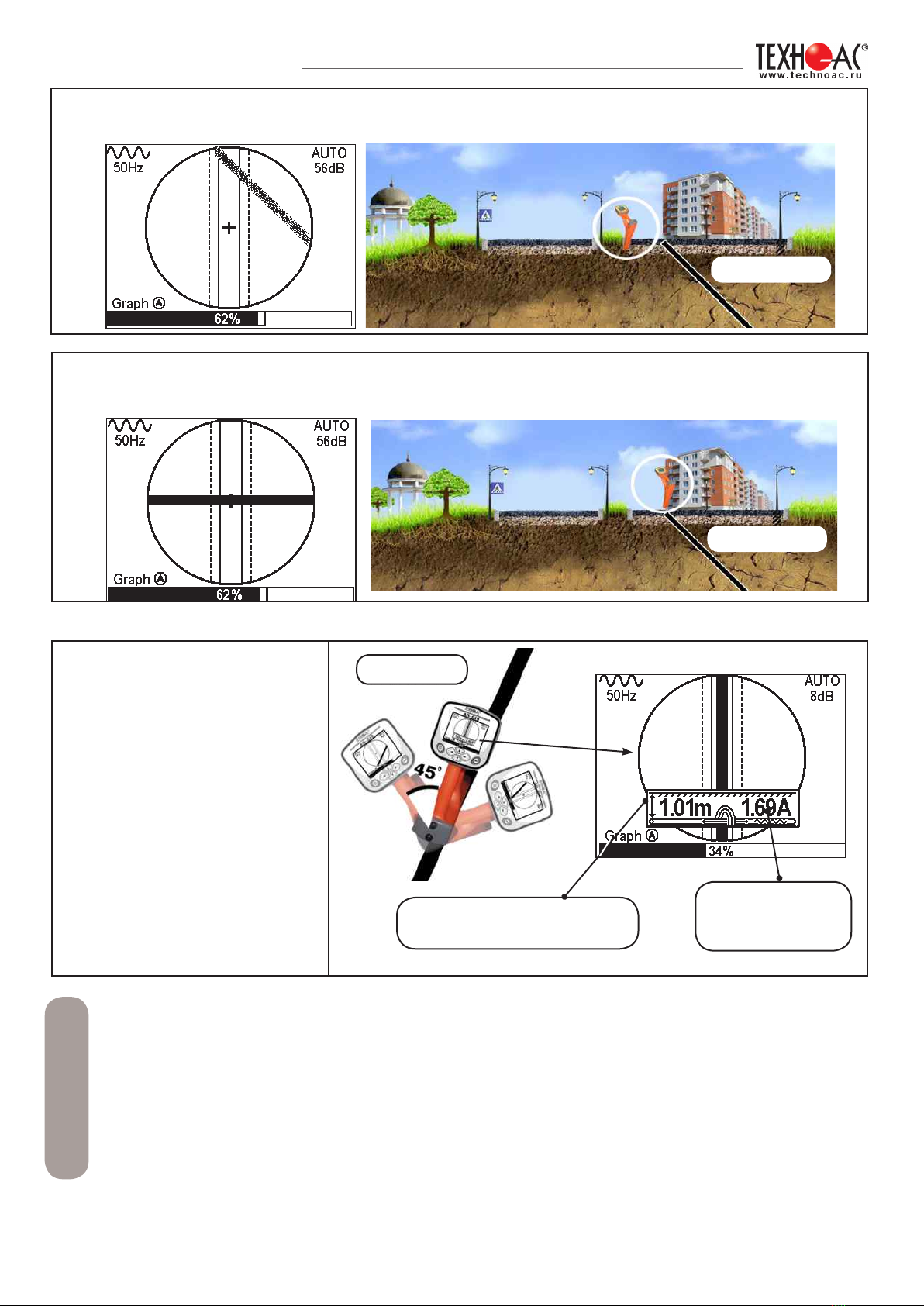
2. If the communication is far from the operator, you will see on the screen:
3. When moving towards the supposed place of the communication location, the «ball» will
appear on the screen. It shows the presence of communication, and that it is on the significant
distance from the operator.
4. The «ball» position shows, in which direction from the operator the communication is located.
4.2 Search of a communication and measurement of its burial depth.
1. Come to the supposed place of the communication under the voltage or induced voltage in
frequency 50(60) Hz.
communication
communication
communication
communication
communication
DEVELOPMENT, MANUFACTURING AND SUPPLY OF INSTRUMENTATION
13
The power cables most frequently lay at the depth of 60-80 cm, allowing to differ them from
pipelines. It is possible that cable lays in one channel with the pipeline, when the burial depth
can be significantly exceed 1 meter.
If the communication axis cannot be located exactly in the limited area, and the periodical
jumps are happening from the one border to the other, it tells about the presence of several
cables under voltage with the 50 Hz frequency. You can specify number and position the cables
in «Graphic» mode.
5. When approaching to the communication at distance less than the doubled burial depth,
the blurred line of the axis pointer will appear.
6. When operator moves closer tothe communication, the axis will move to the circle center.
This means that the operator is standing strictly over the communication.
7. Further you should
rotate the device, until the
communication axis is aligned
along the receiver axis. In this
position and f the current in the
cable is sufficient the window
will appear displaying its burial
depth and current. Now, the
operator stands alongside the
communication.
In this position, it is possible
to move forward and trace
whole cable.)
Note
The measurement of the burial depth of communication
indications of the burial
depth
indications of the
current
Cable
communication
communication

DEVELOPMENT, MANUFACTURING AND SUPPLY OF INSTRUMENTATION
14
In the case when the signal is significantly distorted, the receiver automatically shows the notice
about field distortion, offering switching the mode to ‘Graph’
the receiver switches the
«Graphic» mode
the dialog box appears «Should a
message about the field distorted
be further displayed?
a hint for switching to the «Graphic»
mode by pressing button
4.3 Hot keys for work in the «Route» mode
The filter on the receiver is set manually in accordance with the selected generator frequency.
When locating the cable route in the conditions of the large number of surrounding utilities
you should set the frequency to 512 Hz.
When it is impossible to ground communication, you should select higher frequencies. To
perform the cable location with damage detection, you should select the higher frequencies.
Transmitter Connection
Contact mode
The generator output is connected directly
to the communication
Contactless method
using the transmitting antenna
4.4 Cable route location in the active mode
This mode is used to locate the power cables under voltage (and without voltage) and other
current-conductive communications, using the external generator. The route location is possible at
frequencies 512, 1024, 8192, 32768 Hz.
Note

DEVELOPMENT, MANUFACTURING AND SUPPLY OF INSTRUMENTATION
15
external
generator
communication
Note
Contactless method
using the induction clamps
communication
external
generator
transmitting
antenna
Inductive clamps
external
generator
communication
DEVELOPMENT, MANUFACTURING AND SUPPLY OF INSTRUMENTATION
16
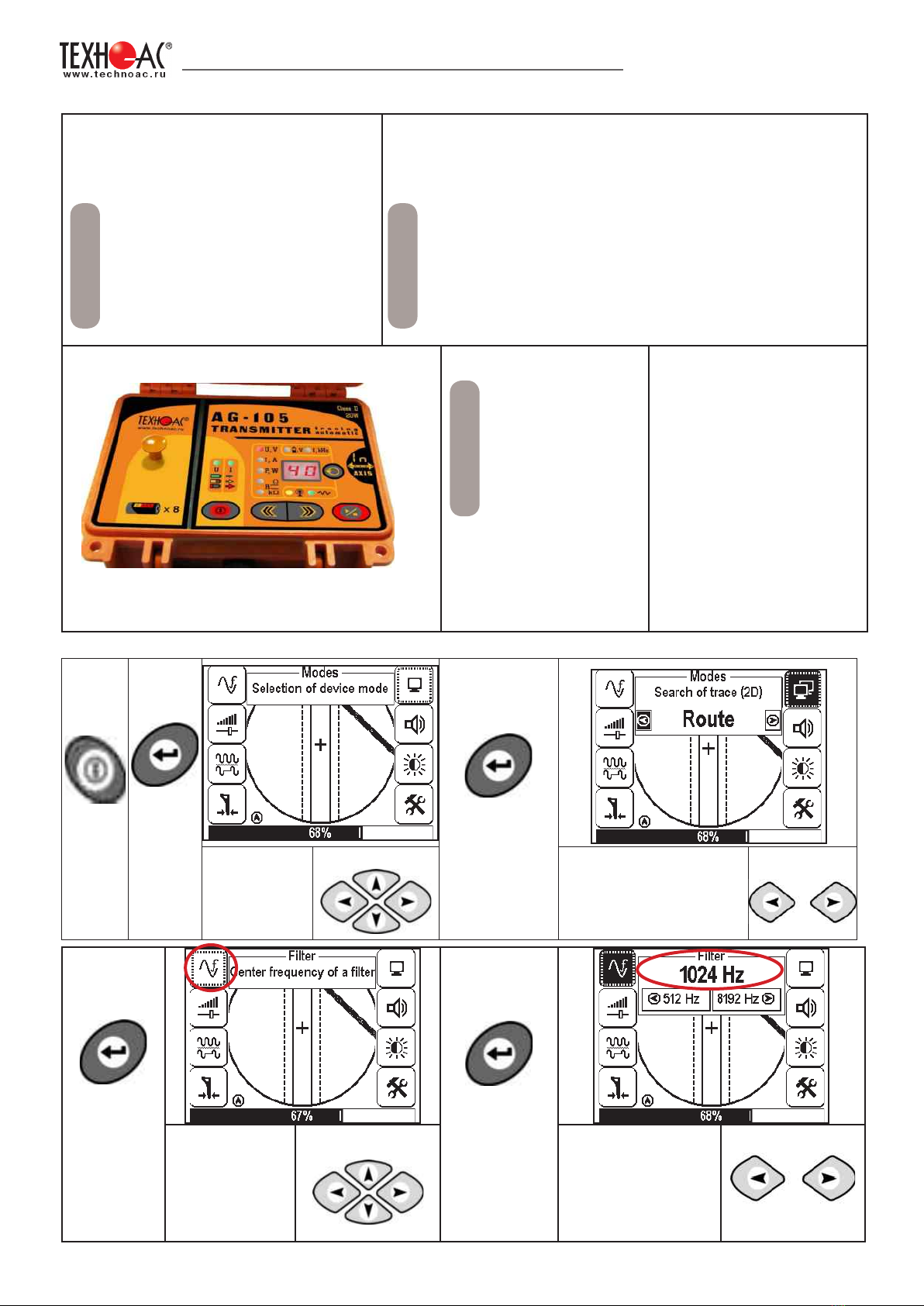
Setting of the receiver for the active search. «Route» mode
Turn
on the
power
Press
‘Enter’
button to
open the
menu
To confirm
your selection
press ‘Enter’
button.
Select
the icon
«Modes» in
the menu.
buttons
Select the «Route»
mode
buttons
Procedure for search of communication and conduction of cable route location
1. Connect the generator to
the communication by contact
or contactless method.
When possible, the
preference should be given
to the contact method of
connection, which allows
to perform the cable route
location for more distantly.
2. Turn on the generator. Set the signal type
- impulse «IM»/continuous «CS» The generation
frequency on the generator -
512, 1024, 8192, 32768
Hz.
Impulse mode (IM) It is used to increase the
time of work of generator.
Continuous signal (CS) allows to conduct
simultaneously with the routing the diagnostic of
the faults of the power cable
Note
Note
The example of setting of parameters on the
generator.
3. Start the
generation, wait
for the transmitter
to power up.
4. Proceed with the
setting of the receiver
AP-019.1.
Example
Press ‘Enter’
again to
return to
main menu.
To confirm
your selection
press ‘Enter’
button.
Select «Filter» in
the menu.
buttons
Set the filter
frequency
corresponding
to the transmitter
frequency, for
example 1024 Hz.
buttons
DEVELOPMENT, MANUFACTURING AND SUPPLY OF INSTRUMENTATION
17
Press ‘Enter’
again to
return to
main menu.
To confirm
your
selection
press
‘Enter’
button.
Press
‘Enter’
again to
return
to main
menu.
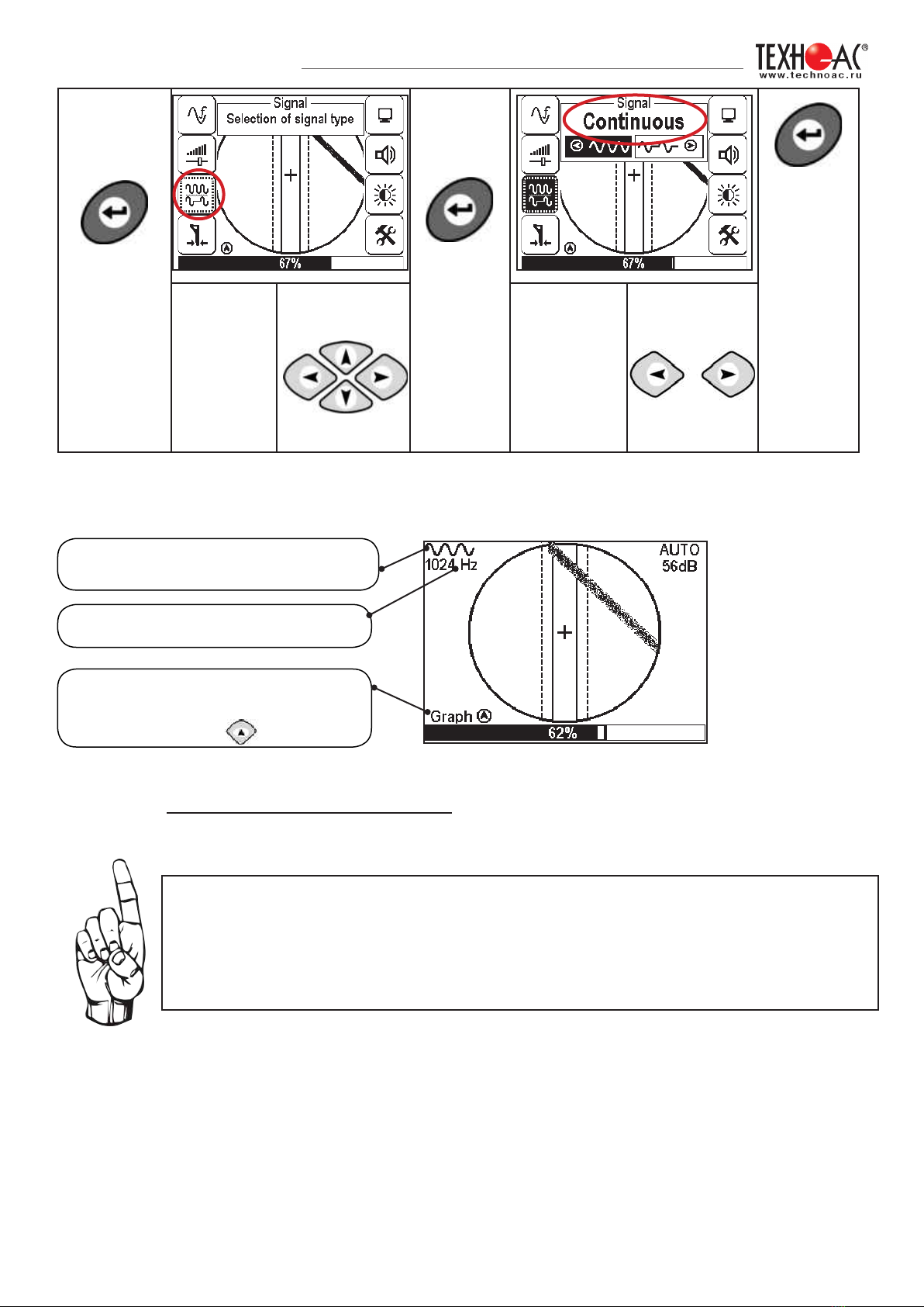
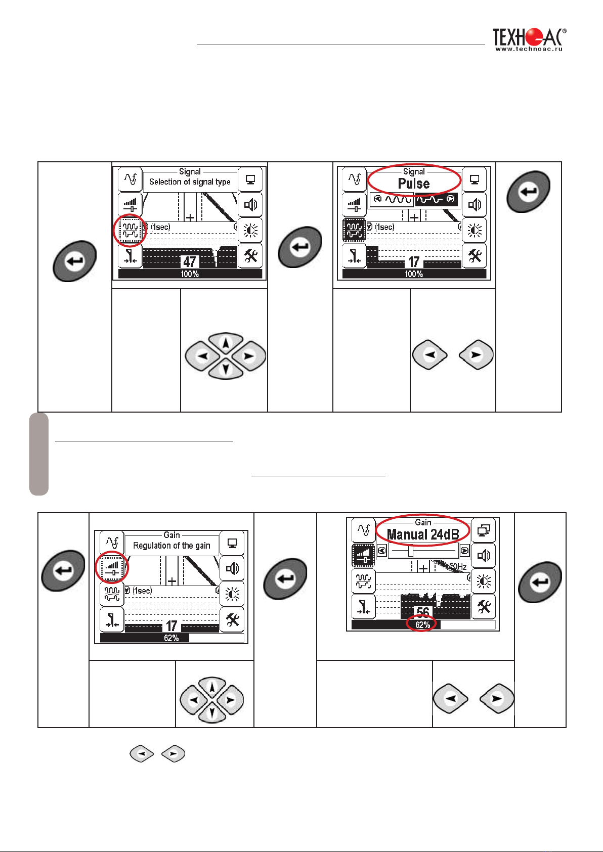
Select
«Signal» in
the menu. buttons
Select the
type of signal
buttons
Having set up the receiver, you can start locating communication and determine its
burial depth similarly to p. 5.2 (page 17)
View of the receiver screen for route location in the active mode
the input signal type set in the receiver
(continuous)
the set filter frequency - 1024 Hz
a hint for switching to the «Graphic»
mode by the short pressing of the
button
When working in the Route mode, sometimes happens the following:
- the positioning of the communication axis into the centre is impossible
- the presence of several near located communications
- low signal in the cable
in such cases you should switch to the «Graphic» mode.
DEVELOPMENT, MANUFACTURING AND SUPPLY OF INSTRUMENTATION
18
5. Search of communications in the mode «Graphic»
The «Graphic» mode of is the support mode and intended to locate various communications
(cables, pipelines), both in the passive and active modes with the route locating transmitter. In the
passive mode the cable location is carried out at frequencies 50(60), 100(120)Hz, in the active
mode - 512,1024, 8192, 32768 Hz.
The «Graphic» mode is also intended to determine the number of the near located communications.
The «Graphic» mode allows to perform the route location in the conditions of the low signal on the
communication, when the route location in the «Route» mode is impossible.
The measurement of the burial depth and current is not available in this mode.
In the «Graphic» mode, the receiver screen displays the moving diagram of change in the signal
level depending on the time by the ‘maximum’ method - when located over the communication the
signal is maximum, when deviating from the axis - the signal decreases.
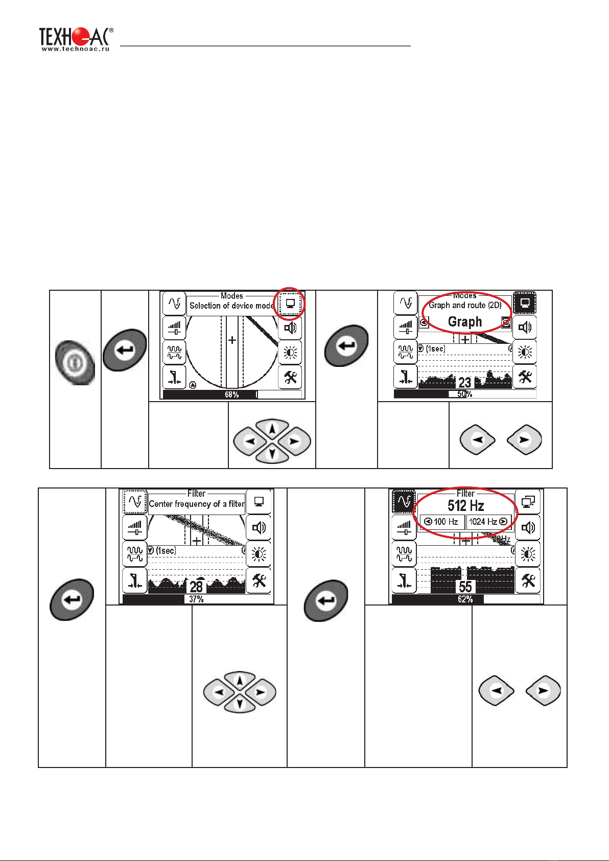
5.1 Setting of the receiver for work in the «Graphic» mode
Turn
on the
power
Press
‘Enter’
button to
open the
menu
To confirm
your
selection
press
‘Enter’
button.
Select
«Modes» in the
menu.
buttons Select
the mode
«Graphic»
buttons
Press ‘Enter’
again to
return to
main menu.
To confirm
your selection
press ‘Enter’
button.
Select the
«Filter» in the
menu.
buttons
Set the filter
frequency for the
passive search
50(60) or 100(120)
Hz, for active
search 512, 1024,
8192 Hz , 33 kHz in
accordance with the
generator frequency
buttons
At the active search, the signal should be transmitted on the route from the generator with the same
frequency as on the receiver (p.5.3).
DEVELOPMENT, MANUFACTURING AND SUPPLY OF INSTRUMENTATION
19
Press ‘Enter’
again to
return to
main menu.
To confirm
your
selection
press
‘Enter’
button.
Press
‘Enter’
again to
return
to main
menu.
Select
«Signal» in
the menu. buttons
Select the
signal type,
for example,
impulse, and
in accordance
with the
generator
signal
buttons
In the «Graphic» mode the work is performed in the «Continuous» or «Impulse» signal. The
difference at the work with the «Impulse» signal is in that the digit in the center of the analogous
scale shows not the current value of the signal, but the maximum value (amplitude) of the
transmissions of the interruptible signal from the route locating generator. The pitch of the tone
of the sound synthesized also corresponds to the maximum value of the signal for the period of
the impulse transmitted.
Press
‘Enter’
button
to open
the
menu
To confirm
your
selection
press
‘Enter’
button..
the signal level on the bottom scale
should be in the range 50 to 50%
Press
‘Enter’
again to
return
to main
menu.
Select
«Amplification»
in the menu.
buttons Set the amplification
coefficient, for
example,
24 dB
buttons
During the route location, you can manually set the input signal amplification.
The change of the input signal amplification coefficient should be performed
manually by short pressing buttons or semi-automatically by holding
one of them pressed for 1 sec.
In the «Graphic» mode it is possible to listen synthesized sound through the built-in speaker,
The sound tone pitch changes depending on the signal level.
When working in the passive mode 50(60) Hz, 100(120) Hz - you should always select the
continuous type of the signal.
When working with the generator (in the active mode) 512, 1024, 8192 Hz, 33 kHz - the
type of the signal on the receiver is continuous or impulse, in accordance with the signal set
on the transmitter.
Note
DEVELOPMENT, MANUFACTURING AND SUPPLY OF INSTRUMENTATION
20
5.2 «Hot» keys for work in the «Graphic» mode
Press
‘Enter’
button to
open the
menu
To confirm
your
selection
press
‘Enter’
button.
Press ‘Enter’
again to return
to main menu.
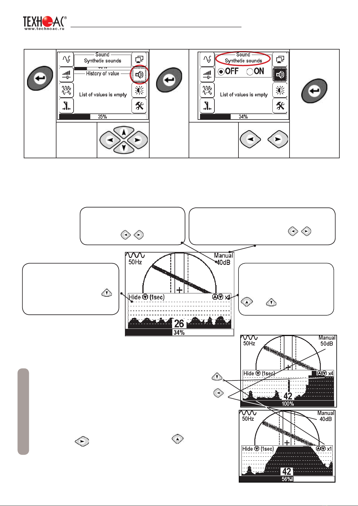
Select
«Sound» in
the menu
Select
necessary
parameter
increase/decrease of the image xl,
х2, х4,х8 by the short pressing of
the buttons
and correspondingly
turning off the Graphic mode and
switching to the Route mode by
long pressing button
decrease / increase coefficient of
the amplification, shortly press semi-automatic setting of the optimum amplication
coefcient - push and hold
Note
If the signal occupies the whole graphic (the black string) it is
necessary to perform the following actions:
1. Decrease the graphic scale to the value x1 by pressing
button
2.Decrease the signal amplification coefficient by
pressing button till the appearance of the decrease of the
input signal level will be less than 80%.
3.In case of low signal, increase the
amplification coefficient by pressing
button and the scale by pressing button.
Other manuals for Success AG-309.15 N
1
This manual suits for next models
1
Table of contents
Other TECHNO-AC Security Sensor manuals

TECHNO-AC
TECHNO-AC SUCCESS CBI-436N Manual

TECHNO-AC
TECHNO-AC Success AT-107N Manual

TECHNO-AC
TECHNO-AC Success CBI-116N User manual

TECHNO-AC
TECHNO-AC SUCCESS-438.15N Manual

TECHNO-AC
TECHNO-AC SUCCESS ATP-434N User manual

TECHNO-AC
TECHNO-AC Success AT-407N Parts list manual

TECHNO-AC
TECHNO-AC SUCCESS TPT-522N Manual


