Technogel FREEZER 200/1 User manual

I
IN
NS
ST
TR
RU
UC
CT
TI
IO
ON
NS
S
F
FO
OR
R
T
TH
HE
E
I
IN
NS
ST
TA
AL
LL
LA
AT
TI
IO
ON
N,
,
U
US
SE
E
A
AN
ND
D
M
MA
AI
IN
NT
TE
EN
NA
AN
NC
CE
E
Ed 2013
GB
FREEZER 200/1

2
Introduction
Thank you for choosing a Technogel machine. To ensure trouble-free operation of your machine, please
read the Instructions for the Installation, Use and Maintenance very carefully.
The descriptions and illustrations contained in this manual are not binding. Technogel Spa reserves the
right to make any changes to the machine for constructional and/or commercial reasons that the company
feels necessary at any time and without prior warning.
CAUTION
In compliance with current Standards regulating personnel safety in the workplace,
the instructions given in the next two sections must be followed very closely.
Authorized personnel
Please note the symbols which appear at the side of each description of work to be carried out in installation,
use and maintenance of the machine:
= Technician = User
Where the Technician symbol is given (either an electrician, a plumber, a refrigeration expert or a mechanic)
this means that the work must only be carried out by these people. If the work is attempted by the user it
could prove dangerous and is to be avoided at all costs.

3
Instructions for unpacking the machine
FREEZER 200/1 - GROSS WEIGHT 585 KG. NET WEIGHT 460 KG.
Remove all wood packing panels from the sides
and top
Lift the machine using a fork lift truck, inserting the forks
between the base of the machine and the bottom of the
crate
Unscrew the four bolts on the base of the crate which
hold the machine locked in position
CAUTION !
Once the bolts have been removed, the bottom of the
crate will detach from the machine base.
After removing the bottom of the crate, lower the fork lift
carriage and rest the machine on the ground.
THE TYPE OF WOOD USED FOR THE CRATE IS NATURAL PINE AND DOES NOT
CONTAIN ANY CHEMICALS WHATSOEVER. IT CAN THEREFORE BE RECYCLED

4
Instructions for lifting the machine
FREEZER 200/1 - NET WEIGHT = 460 kg.
Raise the machine using a fork lift truck, inserting
the forks under the sides of the machine between
the front and rear wheels.
Lift the machine using belts as shown in the figure
positioned close to the front and rear wheels. The cable
used to raise the machine must be positioned exactly in
the center of the machine.
HOW TO MOVE THE MACHINE
Move the machine using a manual pallet trolley.
Insert the trolley forks either under the side or the
front of the machine.
After positioning the machine, make sure all four legs
rest on the ground. Regulate the feet so that the
machine tilts forward slightly.

5
Positioning of different facilities
CAUTION:
For trouble-free operation of the machine it is not necessary for the machine to be anchored to the floor, nor
are any special measures necessary to limit vibration.
A number of important points should, however, be borne in mind:
- Leave a space of at least 50 cm around the machine. This is indispensable to ensure
maintenance work can easily be carried out on the machine.
- Connect the machine to the electricity supply at point Fwith a cable coming from above to avoid
any danger of crushing underfoot. For power data, please see page 7.
- Make sure the floor is strong enough to take the weight of the machine.
- Check the machine is stable by making sure that the four legs are firmly resting on the floor.
- Connect the machine to the water supply at points Dand Ewith firmly fitted piping which will
withstand a minimum pressure of 10 Bar. For data regarding consumption please see page 8.
- Connect the machine to the compressed air at point AC. For data regarding consumption
please see page 9.
Dimensions of the machine:
A
Width in mm
B
Depth in mm
C
Height in mm
Weight
Kg.
700
1050
1480
460

6
Machine identification
Each machine is fitted with a plate giving the following information:
type of machine
serial number
year of manufacture
voltage, and absorption
electrical power
type and quantity of refrigerating gas
The plate is applied to the rear of the machine. The plate for this machine is as indicated below:
When ordering spare parts and applying for technical assistance, please give the data indicated on the serial
plate to ensure precise identification of the machine:
MACHINE TYPE
FREEZER 200/1
SERIAL N°
VOLTAGE
V._____________ HZ ________

7
Electrical installation
The electrical installation to which the machine is connected must be in compliance with standards
and the electrical work required must be carried out by a qualified electrician. An efficient electrical
installation with adequate earth is of primary importance to ensure trouble-free operation of your
machine.
We recommend installation of a suitable wall mounted differential circuit-breaker. See table (A) for power
supply and absorption data
Check that the power supply is correct for the machine details as indicated on the plate (see page 6).
The machine’s power cable has 4wires: the yellow/green wire is the earth –the other three are the three
phases.
Table (A)
FREEZER 200/1
220 V
50 Hz
220 V
60 Hz
200 V
50/60Hz
400 V
60 Hz
380 V
50 Hz
415 V
50Hz
Total power kW.
8,9
8,9
8,9
Max absorption A.
34
22
22
Power cable
N° of wires and cross section
4 x 6
mm²
4 x 6
mm²
4 x 2,5
mm²
4 x 2,5
mm²
4 x 2,5
mm²
TECHNOGEL DISCLAIMS ALL RESPONSIBILITY FOR DAMAGE ARISING FROM INCORRECT
ELECTRICAL INSTALLATION OR FAULTS IN THE POWER SUPPLY

8
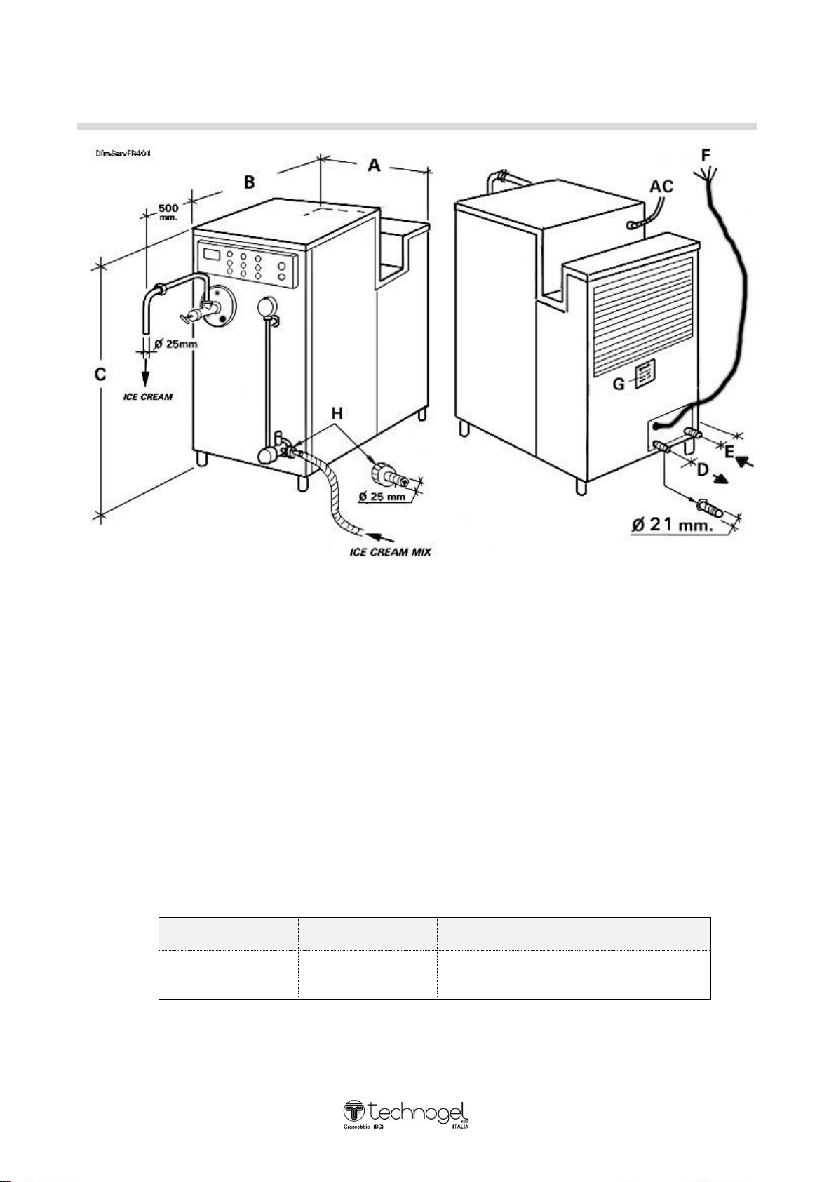
Connection of water supply
The refrigerating system has a water-cooled condenser and it is therefore necessary to connect the pipe
coming from the mains water supply or from the tower water system at the point where the WATER INLET
connection is located on the back of the machine at the bottom and to connect the drainage pipe or pipe
recycling to the water tower system where the WATER OUTLET connection is located.
Please note that it is important to use rubber piping for the water supply connection which is designed to
withstand a pressure of at least 10 bar, with an internal diameter of approx. 21 mm (suitable for the
connectors supplied with the machine).
If there are no labels indicating the water supply INLET and OUTLET, please note that the INLET pipe is
the one that connects to the pressure valve.
- WATER PRESSURE AND CONSUMPTION
If the machine operates on mains water, make sure that the water going into the machine is at least
1 Bar in pressure.
If the machine operates on tower water, make sure that the water going into the machine is at least
2 Bar in pressure with a maximum temperature of 29°C.
In both cases maximum pressure for water entering the machine must not exceed 4 Bar.
WATER TOWER - The average consumption with the refrigerating system in operation is as follows:
FREEZER 200/1 = 1800 litres/hour*
*depending on the temperature of the water on entry
The quantity of water (max. temperature +29°C and minimum pressure 2 Bar) which must circulate in one
hour of the machine.
WATER CITY - The average consumption with the refrigerating system in operation is as follows
FREEZER 200/1 = 350 litres/hour*
In the case of water containing impurities, it is necessary to position a purifying filter to avoid
clogging and/or damage to the pressure valve. If the water is very hard it should be softened with a
special water softening system.

9
Pneumatic connection
Connect filtered and de-humidified compressed air to the special rapid connector AC (see please page 9)
located on the rear of the machine at the top.
The compressed air must be at least 7 Bar in pressure.
The quantity of air required: suction of 11 liters per minute
“Ice-cream mixture” connection
As indicated on page 5, connect a rubber pipe with internal diameter 25 mm and max. 4 metres in length to
point H(rubber holder supplied with machine).
NB Do not use a rigid steel tube
If the maturation tank from which the mixture is taken is over 4 metres away, it is possible to deliver the
mixture using a pump providing the pressure of the mixture on arrival does not exceed 0.5 Bar.
If the pipe leading to the machine is made of steel, the last half metre of pipe must be rubber.

10
Initial start-up
CAUTION IMPORTANT
TO CARRY OUT INITIAL START-UP, PRESS THE “START”
BUTTON AND THEN WAIT FOR AT LEAST 60 MINUTES BEFORE
ACTIVATING THE REFRIGERATOR COMPRESSOR.
IF THE MACHINE IS DISCONNECTED FROM THE POWER SUPPLY
FOR ONE DAY OR MORE, AFTER PRESSING THE “START”
BUTTON, IT IS NECESSARY TO WAIT FOR AT LEAST 60 MINUTES
BEFORE ACTIVATING THE REFRIGERATOR COMPRESSOR.
IF THE MACHINE IS NEVER DISCONNECTED FROM THE POWER
SUPPLY NO WAITING PERIOD IS NECESSARY.
COMPRESS

11
Description of machine control panel
Pos.
Components
Function
1
white button "RESET" machine power
illuminated button = applied voltage
Off = Power off button
2
Potentiometer overrun
Nel l'air regulator iced
3
Push button start / stop "group bombs"
Starts and for pumps
4
Ice cream production Viewer
Displays the time-liter ice cream produced
5
Push button start / stop "agitator"
Starts and for the agitator (turbine)
6
Push button start / stop "refrigerator
compressor"”
Starts and stops the compressor fridge
7
Switchboard Meter
Controls and displays ice hardness
8
Push ON / OFF "hot gas"
Hot Gas ON = consent for the injection of hot
gas from the remote 9
OFF = Hot gas injection to stop
9
Manual valve regulating "hot gas" with
gravitational gauge connected
Turning it counterclockwise, hot gas is
introduced. Indicative quantity is detected on
the pressure gauge on the wheel.
10
Alarm lamp
Notice engine failure or shutdown the machine
11
Pushbutton "emergency"
Pressing it will be for the entire machine.
12
Indicator compressed air flow
Nel air Indicator% cream in the regulation is
check with the potentiometer (2)
14
Pressure gauge indicating the pressure /
temperature condensation of the
refrigeration
Indica, with the machine running. pressure /
condensing temperature
15
Pressure gauge indicating the pressure /
temperature Evaporation of the
refrigeration
Indica, with the machine running, the pressure
/ temperature evaporation

12
Instructions for dismantling mixer turbine: first time then
Check that the “EMERGENCY” button 11 (page
10) is off and that the power supply to the control
panel is therefore disconnected.
Using the appropriate spanner, dismantle faucet
2 by unscrewing ringnut 1. Unscrew handwheels
4 using the appropriate spanner and dismantle
flange 5 by pulling towards you.
Remove turbine 6 from the freezer tube and, as it
is being extracted, dismantle scraper knives 7.
While dismantling the knives protective gloves
must be worn as the knives are very sharp indeed
and you could cut yourself very easily.
When dismantling, do not drop them as they
could dent.
CHECKING THE DIRECTION OF ROTATION
Check that the “EMERGENCY” button 11 (page
10) is ON and connect the power supply by
pressing the “RESET” button 1 (page 10).
Press the stirrer button 5 and watch the hub to
check which way it rotates by looking through
into the inside of the freezer tube.
It must rotate in a clockwise direction
If it does not do so, disconnect the power supply
and invert any two of the three phases of the
machine power supply cable. Test again to check
the direction of rotation.
TAKE CARE WHEN HANDLING THE KNIVES AS THEY ARE VERY SHARP
AND YOU COLD CUT YOURSELF

13
Correct assembly of the turbine and knives
Before reassembling the turbine, check that the packing gland (1) is correctly mounted:
-the locking foot (2) on the spring must fit in its seat.
-The rotating part (3) of the packing gland must be free to move along the axle of the turbine (4) with
the force of the spring. If the rotating part (3) of the packing gland is blocked with the spring
crushed, it is necessary to dismantle it by removing it from the axle (4) and to grease the washer
inside using vaseline.
(1)
When re-assembling the turbine in the freezer tube, make sure the scraper knives are mounted correctly.
Correct assembly is as shown below:
INCORRECT
ASSEMBLY
CORRECT
ASSEMBLY
DIRECTION OF
ROTATION
WHEN ASSEMBLING THE TURBINE IN THE MACHINE, BE CAREFUL NOT TO SCRAPE THE
CHROME ON THE OUTSIDE OF THE FREEZER TUBE. ASSEMBLE SLOWLY AND CAREFULLY.

14
AUTHORIZED AND UNAUTHORIZED USAGE
TECHNOGEL FREEZERS are specially designed for the manufacture of ice-cream.
If the machines are used for any other purpose than the production of ice-cream the
Customer does so at his own risk.
Conditions of usage
Quantities the machine can produce: minimum quantity is half its production rate (i.e. 100 litres of ice-cream
with 100% increase in volume; maximum quantity (200 liters of ice-cream with 100% increase in volume).
The temperature of the ice-cream produced will depend on the type of mixture used and the quantity of ice-
cream produced.
The minimum increase in volume recommended to obtain good quality ice-cream is 30%.
THE PRODUCTION QUANTITIES INDICATED CAN BE OBTAINED WHEN THE CONDENSATION
TEMPERATURE OF THE REFRIGERATING PLANT IS BETWEEN 35°C AND 40°C
(OPTIMUM CONDENSATION)
WITH CONDENSATION OF OVER 45°C, THE MACHINE’S PRODUCTION IS GREATLY
REDUCED. OPERATING UNDER THESE CONDITIONS OVER A LONG PERIOD OF TIME
COULD DAMAGE THE REFRIGERATING PLANT.

15
Operation of the machine
Press the “RESET”pushbutton 1to operate the machine and ensure that all the motors can be started up.
Press pushbuttons 3(pump), 5(stirrer) and 6(fridge compressor) to start the relative motors. When the
pushbuttons light up, this means the relative motor has started; when the lights are off, this means the
relative motors are stopped.
Caution: pushbutton 3(pump) can be on or off as required irrespective of the others. However, if
pushbutton 5is not pressed (stirrer), the fridge compressor (pushbutton 6) will not operate.
Adjusting the pump flow rate and therefore the production of ice cream
To regulate the production of the machine, increases or decreases the speed of the pumps (and hence, the
production of ice cream now) with the handwheel black (pos. T p. 15) placed on the front of the machine.
The pump is displayed by the display of the flow rate 4 L / h and the production of ice cream with 100%
overrun.
(See Page 16)
The pump flow must be associated with the injection of air into the ice cream to be made manually with the
regulator. See the following pages how.
- Display of “viscosity”
During operation of the machine, display 7gives the “viscosity” value for the ice-cream at that particular
moment in time. This numerical value (Ampere), which is low at the start and higher as the ice-cream comes
ready, is only indicative and enables the operator to check that the flow of ice-cream is constant during
production.
The maximum viscosity data is set when the machine is commissioned and if this figure is exceeded
(maximum ice-cream hardness) the ampere system inside display 7 will automatically stop the fridge
compressor for a few seconds and it will then start again once the value returns within normal parameters.
- Connection of “hot gas”
Press pushbutton 8 to give the go-ahead for injection of hot gas. The quantity of gas injected is adjusted
using the appropriate regulator 9 and display of the viscosity value appears on display 7. Instructions are
given on the following pages.

16
Start-up of the machine
Connect the Freezer pump unit to a storage mixing tank with a pipe
Amade of rubber or flexible plastic. The pipe must not be more
than 4 meters in length.
A rigid stainless steel tube should not be used.
Before starting the machine, open faucet Bso that the thread of the
handwheel protrudes by approx. 4.5 cm.
Connect the panel to the power supply by pressing button C
“RESET” (light on).
Start the pump unit on pushbutton .
Turn handwheel (T) (pump speed adjustment) clockwise to position
1.5 (black hand)
Set the air regulation valve (S) at the minimum value: Screw the
handle (4) clockwise till it gets fixed.
The first load of mixture must be without air.
When the liquid mixture begins to emerge from the outlet pipe,
tighten handwheel Bso that the thread is approximately 1 cm from
the faucet.
Wait for the pressure inside the machine to reach 5 Bar (this can be
read on pressure gauge G) and then stop the pump unit using
pushbutton .
Start the mixing turbine and the fridge compressor in that order.
Wait a few minutes and then start the pump again by pressing and inject air in the ice-cream by
unscrewing the handle (4) and manage to drag the ball (5) at the middle of the scale (6).
While the machine is in operation, make sure that the pressure of the ice-cream inside the freezer, as
indicated on gauge G, remains between 10 and 13 Bar by tightening or loosening handwheel Bof the outlet
faucet.
If production is low, the ice-cream will be too hard and the viscosity therefore increases until it stops the
fridge compressor for a few seconds. To solve the problem, increase the pump speed using handwheel T
taking the value which appears on display Eto a higher value (e.g. 200 Lt/h).
If on the other hand production is too high and the ice-cream is soft, therefore viscosità is too low, reduce the
speed of the pump taking the value to 100 Lt/h.
In the next few pages instructions are given to calculate the increase in volume and know what increase in
volume the ice-cream should have.

17
Instructions for calculating ice-cream overrun
To know the exact increase in volume of the ice-cream currently in production, follow the instructions below:
- Take a 1 litre container, fill with the liquid mixture and weigh it. When the tare (weight of empty container) is subtracted,
the net weight of a litre of mixture is obtained.
-Fill the same container with ice-cream, weigh it, subtract the tare and you will have the weight of 1 liter of ice-cream
made from the mixture.
Apply the same formula and you will get the increase in volume in terms of percentage:
WEIGHT OF MIXTURE - WEIGHT OF ICE-CREAM
-------------------------------------------------------------------------- x 100 = %
WEIGHT OF ICE-CREAM
Example: 1 litre of mixture weighs 1kg 50 g and 1 litre of ice-cream made from the same mixture
weights 0.580 kg =
1.050 –0.580 0.470
---------------------- x 100 = ------------ x 100 = 0.81 x 100 = 81%
0.580 0.580
The litre of ice-cream weighing 0.580 kg has an increase in volume of 81%.
To increase or decrease the volume, increase or decrease the pressure of the air injected by the pump by turning knob E
(see page 15).
We recommend increasing or decreasing by 0.2 Bar at a time; wait for the ice-cream inside the machine to be replaced
and after check the new increase in volume. If necessary, change again.
It is possible that the increase or decrease in air pressure will increase or decrease ice-cream production. Check
therefore and if necessary change it by increasing or decreasing the speed of the pump using the “increase” or
“decrease” buttons D(see page 14).
Once the right balance has been found between pump speed, air pressure injected and the correct viscosity of the ice-
cream, the operator will know how to set the Freezer for future start-ups with that type of product.

18
Regulation of ice-cream viscosity with the hot gas valve
When the Freezer is connected to a packing machine, the quantity and viscosity of the ice-cream produced
must be regulated to suit requirements.
If the requirement is less than the quantity your Freezer produces, the ice-cream emerging from the machine
will be too hard and it will be difficult to fill in to the cones, cups, etc.
To solve this problem, the machine is equipped with a hot gas injector which serves to regulate the viscosity
of the ice-cream.
Instructions for regulating ice-cream viscosity with the hot gas:
While the Freezer is in operation, press the “HOT GAS” button N.
Inject hot gas by turning knob Hin an anti-clockwise direction.
To establish the right quantity, check the viscosity value on the
display 7and stabilize it at the value which, in your opinion, is right
for the product currently in production.
Example:
If prior to regulation the value of viscosity appearing on the
display was “8” and the ice-cream is too hard and after injecting
hot gas you see that the ice-cream is okay when the value
displayed is “7.2”, keep this value of viscosity by leaving the hot
gas connected until production is terminated.
Regulation is very sensitive. Just a slight turn of the knob is
sufficient to achieve results.
On termination of production, disconnect the hot gas on the
keyboard and turn knob Hoff completely.
Use of pump safety valves
If the pressure inside the freezer pipe exceeds 15 Bar (pressure indicated on pressure gauge G, the safety
valves VS will off-load the excess mixture onto the ground.
To stop discharge of the mixture, use faucet Band open as much as necessary to take the pressure back to
the current values (from 10 to 13 Bar).

19
Checking operation of the refrigerating system
The machine is fitted with gauges indicating the pressures and operating temperatures of the refrigerating
plant.
During operation it is possible to check whether the refrigerating system is operating correctly:
- High pressure gauge (condensation) R
This gauge measures the condensation; observe
the scale corresponding to the Freon inside the
machine, the temperature, when the machine is in
operation. It should be minimum + 35°C, maximum
+ 40°C.
If the temperature displayed is over +40°C (check
after 5 minutes because at the start it is normal
for the temperature to rise and then fall), this
means that the cooling water reaching the
machine is insufficient. Call the technical service
for them to check it.
- Low pressure gauge (evaporation) P
This gauge measures evaporation, i.e. the
cold produced by the machine. Observe
the Freon scale inside the machine; the
temperature should vary between –26°C
and –29°C.
CAUTION - VERY IMPORTANT NOTE
IT IS EXTREMELY IMPORTANT TO SUPPLY THE PRESSURE AND TEMPERATURE FIGURES ON
GAUGES P AND R TO THE TECHNICAL SERVICE IF THEIR ASSISTANCE IS REQUIRED.
THE DATA MUST ALWAYS BE READ WITH THE MACHINE IN OPERATION
TECHNICAL WORK ON THE MACHINE MUST NOT BE CARRIED OUT BY UNAUTHORIZED
PERSONNEL AS THIS COULD PROVE DANGEROUS FOR THEIR SAFETY

20
Washing the machine
Once production of ice-cream has been terminated, connect the same mixture pipe to a tank containing
water (maximum temperature 70°C) mixed with detergent and disinfectant.
For the type of detergent and disinfectant Technogel advises the customer to request information
from a specialized company such as DIVERSEY/LEVER or HENKEL etc. who will supply a specific
product for this purpose.
NEVER USE CHLORINE TO DISINFECT AS THIS WOULD DAMAGE THE INTERNAL
SURFACES OF THE MACHINE
Pump the water out of the machine by pressing the pump button , turn on the ice-cream outlet faucet
and start the stirrer .
Repeat the operation until the water coming out is clean.
DURING WASHING OPERATIONS, THE REFRIGERATION COMPRESSOR MUST
DO NOT LEAVE THE TURBINE IN OPERATION IF THERE IS NO WATER IN THE MACHINE. EVEN IF THERE IS
WATER IN THE MACHINE THE MACHINE SHOULD NOT BE LEFT IN OPERATION AS IT WILL GIVE EXCESSIVE
WEAR AND TEAR ON THE BUSHINGS AND BLADES. OPERATE FOR 10 SECONDS AND THEN STOP FOR 30
SECONDS AND CONTINUE WITH INTERMITTENT USAGE UNTIL WASHING IS COMPLETE.
When washing is finished, it is essential to empty the refrigeration pipe completely of any residual
washing water. Follow the instructions below:
A) Disconnect power to the control panel by
pressing the “START” button (light off).
B) Unscrew the three handwheels (4) and dismantle
the flange (5) complete with faucet (2).
C) Remove the turbine (6) from the freezer pipe
taking care to dismantle, as they are extracted,
the scraper knives (7). Do not drop them.
D) Dry all the dismantled pieces and the inside of
the freezer pipe.
E) Before re-assembling the various pieces, grease
all the washers on the faucet, packer gland of the
turbine (see page 12) and flange with vaseline.
MAKE SURE THE SCRAPER KNIVES ARE ASSEMBLED CORRECTLY (see page 12).
Table of contents