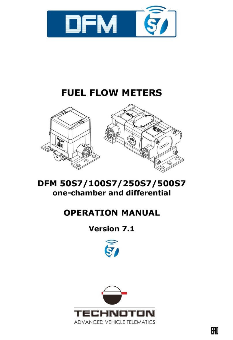
Technoton DFM 50 User manual

Contents
DFM fuel flow meters. Operation manual. Version 8.0
© Technoton, 2020 2
Contents
Contents .................................................................................................................. 2
Revision history......................................................................................................... 4
Structure of external links .......................................................................................... 6
Terms and Definitions ................................................................................................ 7
Introduction.............................................................................................................. 9
1 DFM general information and technical specifications................................................. 12
1.1 Purpose of use and application area .................................................................. 12
1.2 Exterior view and delivery set........................................................................... 16
1.3 DFM models ................................................................................................... 17
1.3.1 Autonomous fuel flow meters with display .................................................... 17
1.3.2 Fuel flow meters with display and interface cable .......................................... 18
1.3.3 Fuel flow meters with interface cable ........................................................... 19
1.3.4 Differential fuel flow meters with interface cable ........................................... 20
1.3.5 Differential autonomous fuel flow meters with display.................................... 21
1.4 Measurement range and accuracy ..................................................................... 22
1.5 Unit structure and operation principle ................................................................ 23
1.6 Technical specifications.................................................................................... 25
1.6.1 Working fluids........................................................................................... 25
1.6.2 Main specifications .................................................................................... 26
1.6.3 Specifications of measuring chambers.......................................................... 28
1.6.4 Power supply modes .................................................................................. 29
1.6.5 Operation modes....................................................................................... 30
1.6.6 Displayed data .......................................................................................... 31
1.6.7 DFM protection from tampering and intervention........................................... 34
1.6.8 DFM pulse output signal specifications ......................................................... 35
1.6.9 Specifications and protocols of RS-232 and RS-485 digital interfaces ............... 36
1.6.10 CAN j1939/S6 digital interface specifications and protocols ........................... 37
1.7 DFM and Telematics terminals compatibility ....................................................... 38
1.8 DFM selection ................................................................................................. 39
1.8.1 Selection depending on engine power (boiler output capacity) ........................ 39
1.8.2 Selection depending on fuel flow rate in feed and reverse lines of the engine .... 40
2 DFM installation .................................................................................................... 41
2.1 Exterior inspection prior to works start .............................................................. 41
2.2 Estimation of the fuel consumer condition .......................................................... 42
2.3 General installation instructions ........................................................................ 43
2.4 Fuel flow meters mounting schemes .................................................................. 46
2.4.1 Typical diesel engine fuel system scheme..................................................... 46
2.4.2 DFM installation before the pump ................................................................ 47
2.4.3 DFM installation after the pump .................................................................. 49
2.4.4 Differential DFM D installation scheme ......................................................... 51
2.5 Electrical connection........................................................................................ 55
2.6 Flow meters configuration by means of cable connection to the PC........................ 58
2.6.1 Connection DFM to PC................................................................................ 58
2.6.2 User interface ........................................................................................... 61
2.6.3 Authorization ............................................................................................ 62
2.6.4 Working with DFM profile ........................................................................... 63

Contents
DFM fuel flow meters. Operation manual. Version 8.0
© Technoton, 2020 3
2.7 Wireless configuration of flow meters using Android devices ................................. 65
2.7.1 Wireless connection DFM to the Android device ............................................. 65
2.7.2 Interface of S6 application.......................................................................... 68
2.7.3 Authorization ............................................................................................ 69
2.7.4 Operations with profile............................................................................... 70
2.8 Configuration for connection to external terminal unit.......................................... 71
2.9 Operation check.............................................................................................. 73
2.10 Configuration for specific operation conditions .................................................. 75
2.11 Configuration of single-chamber DFM CAN for operation in pairs
in the “Differential”/“Summation” modes ......................................................... 78
2.12 Summation of fuel consumption readings ......................................................... 80
3 Measurement accuracy check ................................................................................. 81
3.1 Test conditions ............................................................................................... 81
3.2 Conducting the tests ....................................................................................... 82
4 Accessories .......................................................................................................... 84
4.1 Mounting kits ................................................................................................. 84
4.2 Connecting cables ........................................................................................... 89
4.3 Additional accessories...................................................................................... 90
4.4 DFM DA 250 deaerator .................................................................................... 92
5 Registered Events control ...................................................................................... 94
6 Diagnostics and troubleshooting ............................................................................. 95
7 Verification .......................................................................................................... 96
8 Maintenance......................................................................................................... 97
9 Packaging ............................................................................................................ 98
10 Storage ............................................................................................................. 99
11 Transportation ...................................................................................................100
12 Utilization/re-cycling...........................................................................................101
Contacts................................................................................................................102
Annex A Overall dimensions and weight ....................................................................103
Annex B Protocol of inspecting machinery unit ...........................................................109
Annex C Template of check test report ......................................................................110
Annex D Modbus RTU data transmission protocol and table of
registers of DFM 232/485 output messages...................................................111
Annex E DFM COM data transfer protocol...................................................................117
Annex F Data composition in the flow meters output messages
that are transmitted via CAN j1939/S6 interface ............................................122
Annex G Electromagnetic compatibility specifications ..................................................128
Annex H SPN of DFM Functional modules ...................................................................129
H.1 Self-diagnostics FM ........................................................................................129
H.2 Onboard clock FM ..........................................................................................131
H.3 Flowmeter FM ...............................................................................................132
H.4 Summator DFM FM ........................................................................................139
H.5 Voltage supply monitoring FM .........................................................................141
H.6 Battery FM ....................................................................................................142
Annex I DFM firmware upgrade ................................................................................143
Annex J Signal cables..............................................................................................144
Annex K Videos .....................................................................................................145

Revision history
DFM fuel flow meters. Operation manual. Version 8.0
© Technoton, 2020 4
Revision history
Version
Date
Editor
Description of changes
1.0
01.2007
Basic version.
6.2
12.2016
OD
•Concept of recommended re-calibration interval of DFM is
introduced. Re-calibration interval of DFM is defined by volume
of fuel went through measuring chamber of DFM.
•Description of new version of flow meter available for order is
added - DFM 250 HP and DFM 500 HP characterized by higher
fuel consumption rate.
6.3
01.2017
OD
•DFM COM data transfer protocol updated.
6.4
06.2017
OD
•Clarifications in DFM order identification codes added.
•Table of measurement range and accuracy is divided in two
separate parts: for one-chamber and for differential flowmeters.
•General installation instructions are amended with description
of symbols on DFM body for proper installation into fuel lines.
7.0
03.2019
OD
•List of DFM CAN output messages according to SAE J1939
protocol updated.
•Information on DFM CAN operation according to NMEA 2000
protocol added.
•List of DFM 232/485 registers of output messages according to
Modbus protocol supplemented with specificators descriptions.
•Tables of SPN of Functional Modules for DFM fuel flow meters
are updated.
•Certificate E28 of E-mark International Standard added.
•Procedure for DFM wireless connection to an Android device via
Bluetooth using S6 BT Adapter added, as well as the flow meter
configuration via the Android device using the
Service S6 DUT-E (Android) mobile application.
•New information screens added (resettable Counters of total
fuel consumption and time of operation) for flow meters models
with displays.
•Feature of correcting the differential fuel consumption using the
correction coefficients set by means of service software for
specific modes of operation of DFM D added.
•The flow meters model codes updated.
•Detailed information on electromagnetic compatibility added.
•Structure of external links for websites and documents added.
•List of Telematics terminals compatible with DFM fuel flow
meters updated.
•Information on MK DFM mounting kits updated.
•Document terminology updated (CAN j1939/S6 Telematics
interface, S6 Technology and IoT Burger Technology).

Revision history
DFM fuel flow meters. Operation manual. Version 8.0
© Technoton, 2020 5
Version
Date
Editor
Description of changes
7.1
11.2019
OD
•The list of output messages of DFM CAN fuel flow meters is
updated; the data composition for PGN that are transmitted
according to SAE J1939 and NMEA 2000 protocols is provided.
•Information on Modbus RTU data transmission protocol for
DFM 232/485 fuel flow meters with examples of
Request/Response messages for data reading is added.
•Minimal requirements for PC for work with Service S6 DFM
service software are added.
•The procedure for elimination of problems that arise sometimes
in relation to running Service S6 DFM software in Windows 10 is
described.
•A Certificate of the Declaration of Conformity of DFM fuel flow
meters to the RoHS Directive (Restriction of Hazardous
Substances) is added.
8.0
06.2020
OD
•Improvement of design of differential DFM D models of flow
meters (new casing cover made of polymer composite)
(see Introduction, 1.3, 2.3, annex A).
•New functional capabilities of DFM CAN fuel flow meters during
their operation according to S6 Technology:
- Uniting up to 16 pcs. flow meters to form a network
(see Introduction, 1.1, 1.6.10, 2.8, annex H.1);
- Application of single-chamber flow meters in pairs for operation
in the “Differential”/“Summation” modes of measurement (see
Introduction, 2.4.4, 2.11,annex H.3);
- Summation of fuel consumption readings of up to 16 pcs. of
flow meters using the Summator DFM Functional module (see
Introduction, 2.12,annex H.4).
•The list of ouput messages and the data composition of DFM
CAN fuel flow meters transmitted via CAN j1939/S6 interface
(see annex F) are updated.

Structure of external links
DFM fuel flow meters. Operation manual. Version 8.0
© Technoton, 2020 6
Structure of external links
DFM fuel flow meters. Operation manual
Document Center
S6 Website
Part S6 Data Base
Part S6 Functional modules
JV Technoton Website
Part Technical support
Part Software/Firmware
YouTube Technoton
ORF 4 Website
Page DUT-E
Page DUT-E GSM
Page DUT-E 2Bio
Page CANUp
Page DFM
CAN j1939/S6 Telematics interface.
Operation manual
Page DFM Marine
Technoton Engineering Website
Page DFM Industrial

Terms and Definitions
DFM fuel flow meters. Operation manual. Version 8.0
© Technoton, 2020 7
Terms and Definitions
IoT Burger is the Technology of creating smart sensors and complex telematics
IIoT devices operating in real time with built-in analytic features
(further on –IoT Burger). The basis of IoT Burger is the software/hardware core,
a set of ready-to-use universal Functional Modules, the database of standartized
IoT parameters.
Particular features of IoT Burger:
•inbuilt analytic features for maximum treatment of signals within the device itself;
•a possibility to design devices with extremely low power consumption;
•doesn’t require programming in the majority of applications, flexible setup;
•using inexpensive industrially manufactured equipment parts;
•measurement and treatment of “quick” processes which is impossible to implement
using cloud technologies;
•an option of ready Reports delivery to the user avoiding server platforms;
•the inbuilt system of data authenticity assurance (self-diagnostics, authorization,
impact control).
The technology provides for the availability of several measurement channels in any device
including pre-set analytical treatment (filtration, linearization, thermal compensation) and
the controlled error of measurement.
Devices created using IoT Burger may be united to form a wire-connected or wireless
connection network. Data may be transmitted to the telematics server, to popular
IoT platforms, by SMS, E-mail, to social networks.
At present, GSM 2G/3G data transmission standards are used in devices with IoT Burger.
The reports transmitted contain data on instant and average values of Parameters,
Counters, Events. The flexible system of Reports setup enables the user to select the
optimal ratio of the data completeness and the volume of traffic.
DFM fuel flow meters is designed using IoT Burger Technology.
S6 is the Technology of combining smart sensors and other IoT devices within one
wire network for monitoring of complex stationary and mobile objects: vehicles,
locomotives, smart homes, technological equipment etc. The Technology is based
and expands SAE J1939 automotive standards.
Information on cabling system, service adapter and S6 software refer to
CAN j1939/S6 Operation manual.
PGN (Parameter Group Number) —is a combined group of S6 parameters, which has
common name and number. Functional modules (FM) of the Unit can have input/output
PGNs and setup PGNs.
SPN (Suspect Parameter Number) —informational unit of S6. Each SPN has determined
name, number, extension, data type and numerical value. The following types of SPN exist:
Parameters, Counters, Events. SPN can have a qualifier which allows qualification of
parameter’s value (e.g. – Onboard power supply limit/Minimum).
ORF 4 —is the Telematics service by Technoton developed for receiving and
processing Onboard reports via Internet, displaying Operational data
overlapped on area maps, information storage in database and Analytical
reports generation upon user’s request.
NMEA 2000 —is a high-level network protocol, which is defined by international standard
of marine electronic equipment NMEA 2000 Standard. NMEA 2000 protocol allows to
combine several units of marine equipment into a single network for data exchange. NMEA
2000 is based on data transfer protocol, which is used in CANbus.

Terms and Definitions
DFM fuel flow meters. Operation manual. Version 8.0
© Technoton, 2020 8
GNSS (Global Navigation Satellite System) —System for area positioning of an object
through satellite signal processing. GNSS is composed of space, ground and user segments.
Currently, there are several GNSSs: GPS (USA), GLONASS (Russia), Galileo (EU),
BeiDou (China).
Analytical report —report generated in ORF 4 on vehicle or group of vehicles operation
for chosen time period (usually a day, week or month). Can be composed of numbers,
tables, charts, mapped route of vehicle, diagrams.
Onboard equipment (OE) —Telematics system elements, directly installed in Vehicle.
Onboard reports (the Reports) —information about vehicle which is returned to a user of
Telematics system in accordance with inputted criteria. The Reports are generated by a
terminal unit both periodically (Periodic reports) and on Event occurrence (Event report).
Route —coordinates, speed and direction of vehicle movement. It matches with the route
of the vehicle on the road. The map is displayed in the form of lines. Vehicle direction is
displayed in the form of arrows.
Parameter —time-varying or space characteristic of the Vehicle (SPN value). For example,
speed, fuel volume in the tank, hourly fuel consumption, coordinates. Parameter is usually
displayed in the form of graph, or averaged data.
Server (AVL Server) —hardware-software complex of Telematics service ORF 4, used for
processing and storage of Operational data, formation and transmission of Analytical reports
through Internet by request of ORF 4 users.
Event —relatively rare and sudden change in SPN. For example, applying the magnetic
field to the fuel flow meter in order to falsify indications of the hourly fuel consumption is
the “Interference” Event. An Event can have one or several characteristics. Thus, the
“Interference” Event has the following characteristics: date/time and duration of the
interference. When the Event occurs, a terminal unit registers the time of occurrence, which
is later mentioned in a report on the event. Thus, the Event is always attached to exact time
and place of occurrence.
Counter —cumulative numerical characteristic of Parameter. Counter is displayed by a
single number and over time its value is increasing. Examples of counters: fuel
consumption, trip, engine hours counter etc.
Telematics terminal (Terminal, Tracking device, Telematics unit) is a unit of Telematics
system used for reading the signals of Vehicle standard and additional sensors, getting
location data and transmitting the data to the Server.
Telematics system —complex solution for vehicle monitoring in real time and trip
analysis. The main monitored characteristics of the vehicle: Route, Fuel consumption,
Working time, technical integrity, Safety. In includes On-board report, Communication
channels, Telematics service ORF 4.
Vehicle an object controlled within Telematics system. Usually Vehicle means a truck,
tractor or bus, sometimes a locomotive or river boat. From Telematics system point of view,
stationary objects are also considered to be vehicles: diesel gensets, stationary tanks,
boilers/burners.
Function module (FM) unit-embedded component of hardware and software combination,
executing a group of special functions. Uses input/output PGNs and settings PGNs.
Unit is an element of vehicle on-board equipment compatible with S6 bus, which uses
S6 Technology.

Introduction
DFM fuel flow meters. Operation manual. Version 8.0
© Technoton, 2020 9
Introduction
The Operation manual contains guidelines and rules which refer to DFM fuel flow meters
(hereinafter DFM), models codes —01…04, 06…09, 11…18, 20…34, 40…47, 50…57,
60…67 developed by JV Technoton, Minsk, Belarus.
DFM model code is defined by first two digits of its serial number, which is placed on
measurement chamber’s body and on packaging label:
The manual contains information on design, operation principle, specifications and
instructions on installation, use and maintenance of DFM and defines the procedure for their
configuration by means of cable connection and wireless connection.
—precise tool for fuel consumption measurement of vessels,
locomotives, diesel generators, burners, quarrying machinery. DFM could be used
both as a part of Telematics system and autonomously.
DFM features:
•compliance with Units, Database and cabling system S6 Technology;
•IoT_Burger Technology provides internal data processing (Parameter filtration and
normalization, Events logging, Counters recording) for easier server operation and
data traffic saving;
•recording real fuel consumption and operation time of fuel consumer –total and in
different consumption modes: “Idle”, “Optimal”, “Overload”, “Tampering” and
“Interference”;
•implementation of data transfer using NMEA 2000 marine equipment communication
protocol allows to integrate the flow meter into ship automation systems*;
•maximum information richness of output data and high reliability of data
transmission over digital interfaces*;
•unique self-diagnostics feature to monitor the stability and accuracy of data*;
•thermal correction function with adjustable coefficient which ensures automatic
correction of values to the ambient temperature**;
•setting the boundaries of operation modes for hourly consumption**;
*For DFM CAN.
** For DFM with interface cable.

Introduction
DFM fuel flow meters. Operation manual. Version 8.0
© Technoton, 2020 10
•feature of fuel consumption correction during differential measurement in different
modes of engine operation using correction coefficients ensures enhanced reliability
of measurement*;
•combination of 1…16 flow meters into a single network using S6 Technology**;
•Possibility to apply methods of differential measurement or summation of fuel
consumption readings in case of single-chamber flow meters connection in pairs**;
•Summation of fuel consumption readings of up to 16 pcs. fuel flow meters**;
•protection against unauthorized interference in operation and data “tampering”;
•resettable Counters of liquid consumption and operation time of flow meter;
•embedded battery allows data (Counters, Events) storage in the internal non-volatile
memory of flow meter when external power supply is switched off;
•accuracy of measurement is not decreasing when flow meter is operated in tough
operation conditions, shaking and vibrations;
•minimum fluid flow resistance;
•built-in mud filter;
•100 % of DFM are verified with a certified metrological test rig;
•Casing cover which is made of polymer composite material*** ensures:
the enhancement of the flow meter endurance towards mechanical loads, the
improvement of electrical insulation and protection from inside condensation, lower
weight;
•full set of high-quality elements for installation;
•conformity with European and national standards and directives;
•rich experience accumulated during the period of its use, high-quality
technical support and documentation.
* For differential flow meters with the firmware version not lower than 4.55,
when using Service S6 DFM software, version 1.24 and higher.
** For DFM CAN with the firmware version not lower than 4.63, when using
Service S6 DFM software, version 1.27 and higher.
***For all differential DFM D fuel flow meters manufactured after 1.10.2019.
See figure 1 for identification codes for DFM ordering.
Example of DFM order identification codes:
“Fuel flow meter DFM 50B”,
(max. flow rate 50 l/h, model - autonomous with display).
“Fuel flow meter DFM 250 AK, 0.5 %”,
(max. flow rate 250 l/h, model - without display, with output normalized pulse, increased
measurement accuracy, inaccuracy is ±0.5%).
“Fuel flow meter DFM 500DK HP”,
(max. flow rate 600 l/h, model - differential without display, with output normalized pulse,
higher maximum consumption rate).
“Fuel flow meter DFM 500CD”,
(max. flow rate 500 l/h, model - differential autonomous with display).
“Fuel flow meter DFM 500CCAN”,
(max. flow rate 500 l/h, model - with display, output interface —CAN j1939/S6).

Introduction
DFM fuel flow meters. Operation manual. Version 8.0
© Technoton, 2020 11
* A symbol is not specified for differential fuel flow meters.
** For autonomous fuel flow meters Zversion is not used.
*** This version is delivered upon special order.
Designation Uis available only for one-chamber flow meters.
Figure 1 —DFM order identification codes
S6 SK service adapter (purchased separately) and Service S6 DFM service software are
used for DFM configuration by means of cable connection to the PC (the current version of
the service software can be downloaded at https://www.jv-technoton.com/, section
Software/Firmware).
For wireless configuration of DFM flow meters with interface cables by means of an Android
device, S6 BT Adapter (purchased separately) and Service S6 DFM (Android) service mobile
application are used (the current version of the service software can be downloaded from
; search request: “Technoton”).
ATTENTION: It is strongly recommended to follow strictly the instructions of the
present Manual when using, mounting or maintaining DFM.
The Manufacturer guarantees DFM compliance with the requirements of technical
regulations subject to the conditions of storage, transportation and operation set out in this
Manual.
ATTENTION: Manufacturer reserves the right to modify DFM specifications that do
not lead to a deterioration of the consumer qualities without prior customer notice.

DFM general information and technical specifications / Purpose of use and application area
DFM fuel flow meters. Operation manual. Version 8.0
© Technoton, 2020 12
1 DFM general information and technical
specifications
1.1 Purpose of use and application area
is designed for (see figure 2):
•fuel consumption measurement in fuel lines of engines of Vehicles
and stationary units;
•monitoring operation time of fuel consumer.
Figure 2 —Purpose of DFM fuel flow meters
Application areas (see figure 3):
1) DFM fuel flow meters can be employed within the Telematics system on vehicles and
tractors and on mobile/fixed equipment, including sophisticated equipment (locomotives,
sea and river vessels, diesel generators, boiler equipment etc.).
a) example of DFM D employment as component of the Telematics system
on Vehicles and tractors

DFM general information and technical specifications / Purpose of use and application area
DFM fuel flow meters. Operation manual. Version 8.0
© Technoton, 2020 13
b) example of using DFM CAN as part of Telematics system
of a complex stationary object
c) example of autonomous DFM C operation
Figure 3 —Application areas of DFM fuel flow meters
DFM installed into a fuel line of fuel consumer, measures hourly (instant) fuel consumption
and generates output signal, which is sent to Telematics unit (see figure 3 a).
Terminal unit gathers, registers, stores received signals and transfers them to telematic
Server. Software installed on the Server generates Analytical reports, which allow time-
related Route control and Vehicle fuel consumption monitoring via web-browser
(see figure 4).

DFM general information and technical specifications / Purpose of use and application area
DFM fuel flow meters. Operation manual. Version 8.0
© Technoton, 2020 14
DFM with pulse output interface provide data on actual fuel consumption of engine
(overall fuel consumption and average instant fuel consumption).
DFM with digital interfaces provide real-time control over extended set of information:
•instant fuel consumption;
•differential/ summary fuel consumption in two fuel lines;
•engine operation time –overall and in different engine operation modes;
•fuel consumption –overall and in different engine operation modes;
•voltage in on-board power network;
•total operation time of flow meter and duration of power-supply from embedded
battery;
•flow meter’s malfunctions;
•evidence of interference to flow meter’s operation.
Availability of CAN j1939/S6 interface allows to connect 16 pcs. of DFM CAN flow meters
and 16 pcs. of DUT-E CAN/DUT-E 2Bio fuel level sensors combined in a single network using
S6 Technology to just one CAN-port of Telematics unit (for example, to CANUp 27 online
telematic gateway) (see figure 3 b).
2) DFM fuel flow meters can be used autonomously (for example, in fuel oil boilers and
burners).
When using autonomous DFM fuel consumption and vehicle operating time data (overall
and in different engine operation modes) is displayed on the built-in LCD display
(see figure 3 c).
Use of DFM provides Vehicle owners with the following:
•actual fuel consumption records;
•registration of machinery working time;
•normalizing of fuel consumption quotas;
•fuel theft detection and prevention;
•real-time monitoring and fuel consumption optimization;
•fuel consumption tests for engines.

DFM general information and technical specifications / Purpose of use and application area
DFM fuel flow meters. Operation manual. Version 8.0
© Technoton, 2020 15
a) Report on the Vehicle route and changes of fuel consumption per hour by the engine
b) Report on modes of the Vehicle engine operation depending
on values of hourly fuel consumption
c) Report on fuel consumption and operation time in each
Vehicle engine mode of operation
Figure 4 —Examples of Analytic Reports based on data from DFM CAN for the selected period
of time created by ORF 4 Telematics service

DFM general information and technical specifications / Exterior view and delivery set
DFM fuel flow meters. Operation manual. Version 8.0
© Technoton, 2020 16
1.2 Exterior view and delivery set
1DFM fuel flow meter –1 pc;
2 Magnetic key*–1 pc;
3Fuse with holder (2 A)** –1 pc;
4Signal cable CABLE DFM 98.20.003 (7.5 m)*** –1 pc;
5Verification certificate –1 pc;
6Specification –1 pc.
Figure 5 —DFM delivery set
*For DFM meters with built-in display.
** Not applicable for autonomous DFM fuel flow meters (see 1.3.1 and 1.3.5).
***Only for DFM meters with pulse interface output.
5
3
2
1
6
4

DFM general information and technical specifications / DFM
models
/ Autonomous fuel flow meters with display
DFM fuel flow meters. Operation manual. Version 8.0
© Technoton, 2020 17
1.3 DFM models
DFM fuel flow meters are represented by the following models:
1) One-chamber —measure volume of fuel passing through engine supply fuel line.
The following models of one-chamber meters are produced:
•autonomous fuel flow meters with display (1.3.1);
•fuel flow meters with display and interface cable (1.3.2):
- with pulse output interface;
- with digital output interfaces;
•fuel flow meters output interface cable (1.3.3):
- with pulse output interface;
- with digital output interfaces.
2) Dual-chamber (bidirectional or differential) fuel flow meters measure fuel
consumption as the difference in volume of fuel flowing through the feed and reverse fuel
lines.
The following models of dual-chamber meters are produced:
•The following modifications of dual-chamber meters with output interface are
available (1.3.4):
- differential meters with pulse output;
- differential meters with digital output interfaces;
•differential autonomous meters with display (1.3.5).
1.3.1 Autonomous fuel flow meters with display
Autonomous fuel flow meters with display (DFM B/C models) —are used in
organizing fuel consumption monitoring system which does not need additional hardware or
software (see figure 6).
Figure 6 —Exterior of autonomous DFM fuel flow meter
Fuel consumption and vehicle operating time data is displayed on the built-in LCD display.
Monitoring and recording is to be performed visually, copying out the data into a fuel
timesheet, by a responsible person.

DFM general information and technical specifications / DFM
models
/ Fuel flow meters with display and interface cable
DFM fuel flow meters. Operation manual. Version 8.0
© Technoton, 2020 18
1.3.2 Fuel flow meters with display and interface cable
One-chamber DFM fuel flow meters with display and interface cable
(DFM CK/C232/C485/CCAN models) (see figure 7) can operate both in the autonomous
mode, and within the Telematics system.
Figure 7 —Exterior of DFM fuel flow meters with display and interface cable
Fuel consumption and vehicle operating time data is displayed on the built-in LCD display.
Fuel consumption data is sent to the pulse output as well (DFM CK).
CAN j1939/S6 (DFM CCAN), RS-232 (DFM C232), RS-485 (DFM C485) digital interfaces
contain fuel consumption data together with Counters values, data on engine operation
modes, flow meter Parameters and malfunctions, Events.

DFM general information and technical specifications / DFM models / Fuel flow meters with interface cable
DFM fuel flow meters. Operation manual. Version 8.0
© Technoton, 2020 19
1.3.3 Fuel flow meters with interface cable
One-chamber DFM fuel flow meters with interface cable (DFM AK/A232/A485/ACAN
models) (see figure 8) are designed to measure fuel consumption within the Telematics
system.
Figure 8 —Exterior of DFM fuel flow meters with interface cable
Fuel consumption data is sent to the pulse output (DFM AK). CAN j1939/S6 (DFM ACAN),
RS-232 (DFM A232), RS-485 (DFM A485) digital interfaces contain fuel consumption data
together with Counters values, data on engine operation modes, flow meter Parameters and
malfunctions, Events.
These models do not have display but have a LED indicator. Flashing light signal indicates
the correct operation of the flow meter measuring chamber.

DFM general information and technical specifications / DFM models / Differential fuel flow meters with interface cable
DFM fuel flow meters. Operation manual. Version 8.0
© Technoton, 2020 20
1.3.4 Differential fuel flow meters with interface cable
Dual-chamber differential DFM D fuel flow meters with interface cable
(DFM DK/D232/D485/DCAN models) (see figure 9) are designed for employment within
the Telematics system. They are installed on vehicles and tractors or on fixed equipment
with up-to-date diesel engines equipped with Common Rail fuel injection systems or pump-
injector units.
Figure 9 —Exterior of differential DFM fuel flow meters with interface cable
Two LED indicators are located on top, on the casing cover of differential DFMs: one
indicates the feed measuring chamber operation (F-red), the other indicates the operation
of the flow meter reverse measuring chamber operation (R-green).
Flashing light signal indicates the correct operation of each of the measuring chambers.
Differential meters calculate fuel consumption as the difference in volume of fuel flowing
through the feed and reverse fuel lines. Data is sent out via pulse output interface
(DFM DK).
CAN j1939/S6 (DFM DCAN), RS-232 (DFM D232), RS-485 (DFM D485) digital interfaces
contain fuel consumption data together with Counters values, data on engine operation
modes, flow meter settings Parameters and malfunctions, Events.
This manual suits for next models
3
Table of contents
Other Technoton Measuring Instrument manuals

