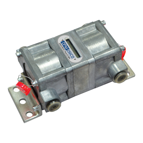
Technoton DFM S7 Series User manual

Contents
DFM S7 fuel flow meters. Operation manual. Version 1.0
© Technoton, 2019 2
Contents
Contents....................................................................................................................... 2
Revision history............................................................................................................. 4
Structure of external links .............................................................................................. 5
Terms and Definitions .................................................................................................... 6
Introduction.................................................................................................................. 8
1 General information and technical specifications ........................................................... 11
1.1 Purpose of use, operation principle and application area .......................................... 11
1.2 Exterior view and delivery set............................................................................... 15
1.3 Models of wireless flow meters.............................................................................. 16
1.4 Measurement range and accuracy ......................................................................... 17
1.5 Unit structure ..................................................................................................... 18
1.6 Technical specifications........................................................................................ 20
1.6.1 Working fluids............................................................................................... 20
1.6.2 Main specifications ........................................................................................ 21
1.6.3 Specifications of measuring chambers.............................................................. 23
1.6.4 Operation modes........................................................................................... 24
1.6.5 DFM S7 protection from tampering and intervention .......................................... 25
1.6.6 Data composition of DFM S7 output message ................................................... 26
1.6.7 Compatibility with receiving devices ................................................................ 29
1.7 DFM S7 selection ................................................................................................ 30
1.7.1 Selection depending on engine power (boiler output capacity) ............................ 30
1.7.2 Selection depending on fuel flow rate in feed and reverse lines of the engine........ 31
2 DFM S7 installation ................................................................................................... 32
2.1 Exterior inspection prior to works start .................................................................. 32
2.2 Evaluation of the fuel consumer condition .............................................................. 33
2.3 General installation instructions ............................................................................ 34
2.4 Fuel flow meters mounting schemes ...................................................................... 37
2.4.1 Typical diesel engine fuel system scheme......................................................... 37
2.4.2 DFM S7 installation before the pump ............................................................... 38
2.4.3 DFM S7 installation after the pump.................................................................. 40
2.4.4 Differential DFM DS7 installation scheme ......................................................... 42
2.5 Wireless transfer of the flow meter indications to the Android device ......................... 45
2.5.1 BLE-module activation ................................................................................... 45
2.5.2 Establishment of communication between the flow meter and the Android device.. 47
2.5.3 Interface of Fuel Consumption Monitor application............................................. 48
2.5.4 Operations with the flow meter Profile ............................................................. 49

Contents
DFM S7 fuel flow meters. Operation manual. Version 1.0
© Technoton, 2019 3
2.6 Operation monitoring........................................................................................... 50
2.7 Monitoring of indications using Fuel Consumption Monitor application ........................ 51
3 Measurement accuracy check ..................................................................................... 52
3.1 Test conditions ................................................................................................... 52
3.2 Conducting the tests ........................................................................................... 53
4 Accessories .............................................................................................................. 55
4.1 Mounting kits...................................................................................................... 55
4.2 Additional accessories.......................................................................................... 60
4.3 DFM DA 250 deaerator ........................................................................................ 62
5 Malfunction diagnostics.............................................................................................. 64
6 Troubleshooting........................................................................................................ 65
7 Verification............................................................................................................... 66
8 Maintenance............................................................................................................. 67
9 Packaging ................................................................................................................ 68
10 Storage.................................................................................................................. 69
11 Transportation ........................................................................................................ 70
12 Utilization/re-cycling................................................................................................ 71
Contacts..................................................................................................................... 72
Annex A Overall dimensions and weight ......................................................................... 73
Annex B Act of the fuel consumer inspection.............................................................................................. 77
Annex C Template of check test report ........................................................................... 78
Annex D Electromagnetic compatibility of BLE-module of DFM S7 ...................................... 79
Annex E Videos ........................................................................................................... 80

Revision history
DFM S7 fuel flow meters. Operation manual. Version 1.0
© Technoton, 2019 4
Revision history
Version
Date
Editor
Description of changes
1.0
12.2019
OD
Basic version.

Structure of external links
DFM S7 fuel flow meters. Operation manual. Version 1.0
© Technoton, 2019 5
Structure of external links
JV Technoton Website
Part Technical support
Part Software/Firmware
YouTube Technoton
ORF 4 Website
Page DUT-E S7
Page GNOM S7
Page DUT-E
Page CANUp
Page DFM
Page DFM Marine
DFM S7 fuel flow meters. Operation manual
Document Center
S6 Website
Part S6 Data Base
Part S6 Functional modules
DUT-E/DUT-E 2Bio/DUT-E GSM.
Installation manual
CAN j1939/S6 Telematics interface.
Operation manual
Technoton Engineering Website
Page DFM Industrial
Page DUT-E GSM
Page DUT-E 2Bio

Terms and Definitions
DFM S7 fuel flow meters. Operation manual. Version 1.0
© Technoton, 2019 6
Terms and Definitions
S7 —Technology designed for wireless collection of data from unattended sensors in
systems of industrial and automobile Telematics. S7 Technology is recommended for
use in facilities where wiring is impossible or hard to install.
S7 Technology implements Bluetooth 4.X Low Energy (BLE) as a communication channel.
S7 Technology provides ultra-low power consumption and a long period of independent
operation for smart sensors and other IoT devices.
On the application level, S7 Technology is fully compatible with S6 Technology which uses
cabling.
Advantages of S7 Technology:
•Simple design of data transmission protocol;
•Low power consumption, a potential for fully independent operation of sensors for
several years;
•Option of data collection by several data recipients at one time.
DFM S7 fuel flow meters are based on S7 Technology.
S6 is the Technology of combining smart sensors and other IoT devices within one
wire network for monitoring of complex stationary and mobile objects: vehicles,
locomotives, smart homes, technological equipment etc. The Technology is based
and expands SAE J1939 automotive standards.
Information on cabling system, service adapter and S6 software refer to CAN j1939/S6
Operation manual.
PGN (Parameter Group Number) —is a combined group of S6 parameters, which has common
name and number. Functional modules (FM) of the Unit can have input/output PGNs and setup
PGNs.
SPN (Suspect Parameter Number) —informational unit of S6. Each SPN has determined name,
number, extension, data type and numerical value. The following types of SPN exist:
Parameters, Counters, Events. SPN can have a qualifier which allows qualification of
parameter’s value (e.g. – Onboard power supply limit/Minimum).
GNSS (Global Navigation Satellite System) —System for area positioning of an object through
satellite signal processing. GNSS is composed of space, ground and user segments. Currently,
there are several GNSSs: GPS (USA), GLONASS (Russia), Galileo (EU), BeiDou (China).
Analytical report —report generated in ORF 4 on vehicle or group of vehicles operation for
chosen time period (usually a day, week or month). Can be composed of numbers, tables,
charts, mapped route of vehicle, diagrams.
Onboard reports (the Reports) —information about vehicle which is returned to a user of
Telematics system in accordance with inputted criteria. The Reports are generated by a
terminal unit both periodically (Periodic reports) and on Event occurrence (Event report).
Parameter —time-varying or space characteristic of the Vehicle (SPN value). For example,
speed, fuel volume in the tank, hourly fuel consumption, coordinates. Parameter is usually
displayed in the form of graph, or averaged data.

Terms and Definitions
DFM S7 fuel flow meters. Operation manual. Version 1.0
© Technoton, 2019 7
Server (AVL Server) —hardware-software complex of Telematics service ORF 4, used for
processing and storage of Operational data, formation and transmission of Analytical reports
through Internet by request of ORF 4 users.
Event —relatively rare and sudden change in SPN. For example, the attempt to falsify values
of “Instant fuel consumption” counter by applying electromagnetic field to fuel flow meter will
be recognized as “Interference” Event. An Event can have one or several characteristics.
“Interference” Event has the following: date/time and duration of interference. When the Event
occurs, a terminal unit registers the time of occurrence, which is later mentioned in a report on
the event. Thus, the Event is always attached to exact time and place of occurrence.
Counter —cumulative numerical characteristic of Parameter. Counter is displayed by a single
number and over time its value is increasing. Examples of counters: fuel consumption, trip,
engine hours counter etc.
Telematics terminal (Tracking device, Telematics unit) is a unit of Telematics system used for
reading the signals of Vehicle standard and additional sensors, getting location data and
transmitting the data to the Server.
Telematics system —complex solution for vehicle monitoring in real time and trip analysis.
The main monitored characteristics of the vehicle: Route, Fuel consumption, Working time,
technical integrity, Safety. In includes On-board report, Communication channels, Telematics
service ORF 4.
Vehicle an object controlled within Telematics system. Usually Vehicle means a truck, tractor
or bus, sometimes a locomotive or river boat. From Telematics system point of view,
stationary objects are also considered to be vehicles: diesel gensets, stationary tanks,
boilers/burners.
Function module (FM) unit-embedded component of hardware and software combination,
executing a group of special functions. Uses input/output PGNs and settings PGNs.
Unit is an element of vehicle on-board equipment compatible with S6 bus, which
uses S6 Technology or S7 Technology.

Introduction
DFM S7 fuel flow meters. Operation manual. Version 1.0
© Technoton, 2019 8
Introduction
The Operation manual contains guidelines and rules which refer to DFM S7 fuel flow meters
(hereinafter DFM S7), models codes: 70 (for DFM 50S7), 71 (for DFM 100S7),
72 (for DFM 250S7), 73 (for DFM 500S7), 35 (for DFM 100DS7),
36 (for DFM 250DS7), 37 (for DFM 500DS7) developed by JV Technoton, Minsk, Belarus.
The model code of DFM S7 is identified by the 3dand 4th digits of its serial number which is
placed on the casing of the measurement chamber and on the packaging label (see figure 1).
Figure 1 —Finding out model code of DFM S7
The manual contains information on design, operation principle, specifications and instructions
on installation, use and maintenance of DFM S7.
—wireless precise tools for direct measurement of fuel
consumption; they can be used both as part of Telematics systems, and as an
independent solution for fuel accounting.
DFM S7 key features:
•wireless transmission of data using S7 Technology via Bluetooth Low Energy channel
simultaneously to many receiving devices (Android-based smartphones/tablets,
the Telematics terminal, the display in the driver’s cabin);
•operation in the «advertising» mode (BLE-radio) —continuous transmission of
measurement results, with no need of integration with receiving devices;
•ultra-low power consumption provides completely independent flow meter operation
during up to 5 years from the inbuilt battery, without the external power supply;
•recording real fuel consumption and operation time of fuel consumer –total and in
different consumption modes: “Idle”, “Optimal”, “Overload”, “Tampering” and
“Interference”;
•storage of indications of all Counters accumulated during the service life of the inbuilt
battery in the internal memory;
•protection against unauthorized interference in operation and data “tampering”;
•no signal cable–quick installation without a need of electrical connection;
•no signal cable —explosive and fire safety of the flow meter is ensured without using
additional modules of explosion protection;
•no signal cable –increase resistance to sabotage;
•function of digital self-diagnostics for flow meter quality control;
•built-in mud filter;
•minimum fluid flow resistance;
•100 % of flow meters are verified with a certified metrological test rig;
•elaborate and high-quality mounting kit accessories;
•high-quality technical support and documentation;
•conformity with European and national automotive standards.

Introduction
DFM S7 fuel flow meters. Operation manual. Version 1.0
© Technoton, 2019 9
To receive DFM S7 indications by means of S7 Technology with a smartphone/tablet based on
Android 5.X and higher operating system (further on —Android device),
Fuel Consumption Monitor mobile application is used, its functionality enables the user to:
•Conduct monitoring of current values of:
- Hourly (instant) fuel consumption *;
- Hourly (instant) fuel consumption for the “Feed” and “Reverse” chambers **;
- Fuel temperature;
•Keep records of:
- Fuel consumption of high resolution —total and separately for modes of operation
“Idle”, “Optimal”, “Overload”, “Tampering” ***;
- Flow meter operation time —total and separately for the modes of operation “Idle”,
“Optimal”, “Overload”, “Tampering”;
- Flow meter operation time in the “Interference” mode;
•Monitor:
- Current engine fuel consumption mode;
- Current mode of operation of the “Feed” and “Reverse” chambers **;
•View in real time:
- Diagram of changing the hourly consumption of fuel which passes through the flow
meter measurement chamber;
- Diagrams of changing the hourly consumption of fuel passing through the “Feed” and
“Reverse” measurement chambers and the diagram of changing the differential hourly
fuel consumption **;
•monitor the flow meter malfunctions;
•Monitor the state of charge of the flow meter inbuilt accumulator;
•receive the flow meter ID data (serial number, firmware version, MAC address of
BLE-module);
•Monitor the indicator of the level of signal received (RSSI) and the time of the latest
message reception from the flow meter;
•Register (log) values of the hourly fuel consumption and its temperature;
•conduct operations with the flow meter profile.
The user may download the Fuel Consumption Monitor application from Google Play
(rearch request “Technoton”) and subscribe to it.
*For DFM DS7 —of the differential hourly consumption of fuel passing through the both
measurement chambers.
** Valid only for differential flow meters.
*** For DFM DS7 —differential total consumption of fuel of high resolution.

Introduction
DFM S7 fuel flow meters. Operation manual. Version 1.0
© Technoton, 2019 10
See figure 2 for identification codes for DFM S7 ordering.
*This version is delivered upon special order.
Designation Uis available only for one-chamber flow meter.
Figure 2 —DFM S7 order identification codes
Example of DFM S7 ordering identification codes:
“Fuel flow meter DFM 100S7”,
(wireless S7 interface, max. flow rate 100 l/h).
“Fuel flow meter DFM 250S7 0,5 %”,
(wireless S7 interface, max. flow rate 250 l/h, increased measurement accuracy,
inaccuracy is ±0.5%).
“Fuel flow meter DFM 500DS7 HP”,
(wireless S7 interface, max. flow rate 600 l/h, differential, higher maximum consumption rate).
ATTENTION: It is strongly recommended to follow strictly the instructions of the
present Manual when using, mounting or maintaining DFM S7.
The Manufacturer guarantees DFM S7 compliance with the requirements of technical
regulations subject to the conditions of storage, transportation and operation set out in this
Manual.
ATTENTION: Manufacturer reserves the right to modify DFM S7 specifications that do
not lead to a deterioration of the consumer qualities without prior customer notice.

General information and technical specifications
/
Purpose of use, operation principle and application area
DFM S7 fuel flow meters. Operation manual. Version 1.0
© Technoton, 2019 11
1 General information and technical specifications
1.1 Purpose of use, operation principle and application area
is used for (see figure 3):
•fuel consumption measurement in fuel lines of engines of Vehicles and stationary units;
•monitoring operation time of fuel consumer;
•wireless transfer of data using S7 Technology.
Figure 3 —Purpose of DFM S7
Operating principle: DFM S7 has an inbuilt Bluetooth Low Energy module (BLE-module)
which, due to a special data transmission algorithm, enables the flow meter operation with
ultra-low power consumption. The BLE-module transmitter switches on automatically once in
5 s to transmit the current indications. Such a mode of operation enables the flow meter to
operate completely independently during no less than 5 years without using any external
power sources; power is supplied only from the inbuilt battery.
Data from DFM S7 can be received at a distance of up to 45 meters by unlimited number of
various receiving devices (Telematics units, Android-smartphones/tablets etc.), which are
equipped with Bluetooth 4.X module.

General information and technical specifications
/
Purpose of use, operation principle and application area
DFM S7 fuel flow meters. Operation manual. Version 1.0
© Technoton, 2019 12
Application areas:
DFM S7 flow meters are mounted in the fuel line of the engine (fuel consumer) in order to
conduct wireless monitoring of fuel consumption and the time of its operation both
independently, and as part of the Telematics system (including without using the services of
the Server):
•on all types of vehicles and tractors (see figures 4 a, b);
•on different fixed objects (diesel generator sets, boiler equipment etc.) (see figure 4 c).
a) monitoring of fuel consumption and the time of vehicles and tractors operation
b) comprehensive monitoring of vehicle operation parameters by means of S7 Technology

General information and technical specifications
/
Purpose of use, operation principle and application area
DFM S7 fuel flow meters. Operation manual. Version 1.0
© Technoton, 2019 13
c) comprehensive monitoring of fuel consumption and operation time of fixed units by means
of S7 Technology
Figure 4 —Examples of areas of application for DFM S7
Due to the availability of the inbuilt BLE-module, up to 8 DFM S7 fuel flow meters and other
wireless Units —DUT-E S7 fuel level sensors (up to 8 pcs.) and GNOM S7 axle load sensors
(up to 4 pcs.) can simultaneously operate using S7 Technology together with
CANUp 27 Pro Telematics gateway (see figure 4 b).
Using GNSS signals, CANUp 27 Pro determines current Vehicle location, movement speed and
direction. In accordance with its settings, the gateway generates and transmits Onboard
reports to the Telematics Server or directly to the user, without using the services of the
Server (by e-mail or in the form of SMS messages). The Onboard reports contain important
performance Parameters of the equipment (e.g. instant and trip fuel consumption, total fuel
consumption, RPMs, fuel level, engine operation time, engine temperature, oil pressure and
level and other parameters). Server software processes and analyzes the received data to
generate Analytical reports for a selected period (see figure 5).
RECOMMENDATION: ORF 4 vehicle monitoring web-server provides the best
accuracy of reports on movement and fuel consumption.
The employment of DFM S7 wireless fuel flow meters allows to solve efficiently the issues of:
•accounting of the actual fuel consumption;
•accounting of the actual equipment operation time;
•rate setting of fuel consumption;
•detection and prevention of fuel theft;
•testing fuel consumption by engines.

General information and technical specifications
/
Purpose of use, operation principle and application area
DFM S7 fuel flow meters. Operation manual. Version 1.0
© Technoton, 2019 14
a) Report on the Vehicle route and changes of fuel consumption per hour by the engine
b) Report on modes of the Vehicle engine operation depending
on values of hourly fuel consumption
c) Report on fuel consumption and operation time in each
Vehicle engine mode of operation
Figure 5 —Examples of Analytic Reports based on data from DFM S7 for the selected period
of time created by ORF 4 Telematics service

General information and technical specifications
/ Exterior view and delivery set
DFM S7 fuel flow meters. Operation manual. Version 1.0
© Technoton, 2019 15
1.2 Exterior view and delivery set
1DFM S7 fuel flow meter –1 pc.;
2 Magnetic key –1 pc.;
3Specification –1 pc.;
4Verification certificate –1 pc.
Figure 6 —DFM S7 delivery set
1
2
4
3

General information and technical specifications
/ Models of wireless flow meters
DFM S7 fuel flow meters. Operation manual. Version 1.0
© Technoton, 2019 16
1.3 Models of wireless flow meters
DFM S7 wireless fuel flow meters are represented by the following models:
1) One-chamber (DFM 50S7/DFM 100S7/DFM 250S7/DFM 500S7 models)
(see figure 7 a) —measure the consumption of fuel flowing through the feed fuel line of the
consumer. They can operate both autonomously, and as part of the Telematics system.
The flow meter transmits in the non-stop “advertising” mode (BLE-radio) indications of fuel
consumption, data of Counters, information of Events, of modes of the engine operation, of the
flow meter Parameters and malfunctions. The data can be received by means of S7 Technology
by all available devices within the range of the flow meter BLE module.
2) Differential (Dual-chamber) (DFM 100DS7/DFM 250DS7/DFM 500DS7 models)
(see figure 7 b) —measure fuel consumption as the difference of volumes of fuel flowing
through the feed and reverse fuel lines of the consumer (differential consumption).
They are installed on vehicles and tractors or on fixed equipment with up-to-date diesel
engines equipped with Common Rail fuel injection systems or pump-injector units.
The flow meter transmits in the non-stop “advertising” mode (BLE-radio) indications of
differential hourly fuel consumption for each chamber, data of Counters, information of Events,
of modes of the engine operation, of the flow meter Parameters and malfunctions. The data
can be received by means of S7 Technology by all available devices within the range of the
flow meter BLE module.
a) one-chamber b) differential
Figure 7 —External view of DFM S7 wireless fuel flow meters

General information and technical specifications
/ Measurement range and accuracy
DFM S7 fuel flow meters. Operation manual. Version 1.0
© Technoton, 2019 17
1.4 Measurement range and accuracy
Table 1 —Measurement range and accuracy of one-chamber
DFM S7
flowmeters
Model
(by size)
Starting flow
rate*, l/h
Minimum flow
rate, l/h
Maximum flow
rate, l/h
Relative accuracy
error, %,
not more than**
DFM 50S7
0.5
1
50
±1
DFM 100S7
2
100
DFM 250S7
2
5
250***
DFM 500S7
5
10
500***
*Minimum threshold flow rate value when the meter starts operating. The value is indicated for reference only
as accuracy is not standardized for operation on the starting flow rate.
** Available for special order one-chamber meters with increased measurement accuracy (see figure 2).
*** Available for special order one-chamber meters with higher fuel consumption rate per chamber (see figure 2).
Table 2 —Measurement range and accuracy of differential DFM DS7 flowmeters
Model
(by size)
Minimum
differential
consumption,
l/h
Minimum flow rate
per chamber,
l/h
Maximum flow rate
per chamber,
l/h
Relative accuracy
error, %,
not more than
DFM 100DS7
5
10
100
±1…3 **
DFM 250DS7
10
50
250*
DFM 500DS7
20
100
500*
*Available for special order dual-chamber meters with higher fuel consumption rate per chamber (see figure 2).
** Depends on ratio of flow rate in feed chamber to flow rate in reverse chamber of DFM DS7.
RECOMMENDATION: In case the average flow rate in engine of Vehicle is close
to the upper capacity limit of a certain DFM S7 model it is recommended to
use DFM S7 with a higher measurement range. That will ensure absence of a fuel flow
meter’s influence on the fuel system as well as longer DFM S7 operating life.

General information and technical specifications
/ Unit structure
DFM S7 fuel flow meters. Operation manual. Version 1.0
© Technoton, 2019 18
1.5 Unit structure
DFM S7 consists*of a ring-type measuring chamber (1), the electronic unit inside of which
there is the BLE module of wireless data transfer by means of S7 Technology and the battery
of autonomous power supply (2), the mounting bracket (3) (see figure 8).
Figure 8 —DFM S7 components
DFM S7 is a direct volumetric fuel consumption measurement device with ring-type measuring
chamber (see animation on DFM fuel flow meter operational principle).
The principle of DFM S7 operation is based on measurement of fuel volume that passes
through its measuring chamber. Because of the pressure of the fuel coming to the measuring
chamber through the inlet fitting the ring slides along the inner surface of the chamber and
along the jumper at the same time. The ring pushes the fluid inside and outside itself out to
the outlet fitting (see figure 9).
The volume of fluid equal to the inner volume of the measuring chamber is pushed out during
the full single turn of the ring. The flow meter electronic unit automatically adds increment
which is equal to the volume of the measurement chamber to the accumulating Counter.
Figure 9 —DFM S7 measuring chamber operation scheme
*DFM S7 one-chamber model is taken as an example for the device presentation.
1
2
3

General information and technical specifications
/ Unit structure
DFM S7 fuel flow meters. Operation manual. Version 1.0
© Technoton, 2019 19
Distinctive design features of DFM S7 fuel flow meters:
•DFM S7 structure provides fluid flow even in case the ring is blocked (e.g. as a result of
clogging of the chamber);
•special coating of the ring ensures its durability and wear resistance;
•measuring chamber is made of durable and lightweight zinc-aluminum (ZA) alloy;
•built-in mud filter effectively protects the chamber from clogging. Filter can be removed
and cleaned without disassembling the body of the DFM S7;
•increased nominal bore for minimum fuel flow hydraulic resistance;
•improved magnetic circuit reduces sensitivity to hydraulic shocks in the engine fuel
system.

General information and technical specifications
/
Technical specifications / Working fluids
DFM S7 fuel flow meters. Operation manual. Version 1.0
© Technoton, 2019 20
1.6 Technical specifications
1.6.1 Working fluids
DFM S7 can be used for following fluids flow measurement:
•diesel fuel;
•heating oil;
•burner oil;
•motor fuel;
•biofuel;
•Other liquid fuels and mineral oils with kinematic viscosity
of 1.5 to 6.0 mm2/s (cSt).
ATTENTION:
1) All DFM S7 units are verified with diesel fuel. Indicate viscosity when ordering
DFM S7 for measuring different fluid type.
2) When operating with fluids having kinematic viscosity over 6.0 mm2/s (cSt) the
upper limit of DFM S7 capacity range will get lower than nominal one and the pressure
drop will increase.
3) DFM flow meters are made of petrol resistant materials. However the declared
lifetime of the measuring chamber is not guaranteed when operating with petrol
(see 1.6.3).
This manual suits for next models
4
Table of contents
Other Technoton Measuring Instrument manuals
Popular Measuring Instrument manuals by other brands
TPI
TPI 580 user guide
Underground Magnetics
Underground Magnetics Mag System manual
Burster
Burster TRANS CAL 7280 Operating instruction
Vibration Research
Vibration Research ObserVR1000 quick start guide
LaserLiner
LaserLiner LaserRangeMaster Pocket Pro manual

Blancett
Blancett 1100 Series Installation instructions manual

