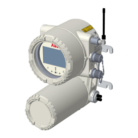
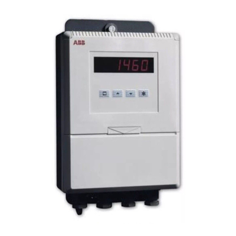
ABB 4630 User manual

pH/Redox (ORP) Analyzers
Models 4630 & 4635
(incorporating Water Wash Versions 4631 & 4636)
Operating Instructions
IM/4600–PH_12

ABB
The Company
We are an established world force in the design and manufacture of instrumentation for
industrial process control, flow measurement, gas and liquid analysis and environmental
applications.
As a part of ABB, a world leader in process automation technology, we offer customers
application expertise, service and support worldwide.
We are committed to teamwork, high quality manufacturing, advanced technology and
unrivalled service and support.
The quality, accuracy and performance of the Company’s products result from over 100 years
experience, combined with a continuous program of innovative design and development to
incorporate the latest technology.
The UKAS Calibration Laboratory No. 0255 is just one of the ten flow calibration plants
operated by the Company and is indicative of our dedication to quality and accuracy.
Use of Instructions
Warning.
An instruction that draws attention to the risk of injury or
death.
Caution.
Aninstruction that drawsattentiontotheriskofdamageto
the product, process or surroundings.
✶
Note.
Clarification of an instruction or additional information.
Information.
Further reference for more detailed information or
technical details.
Although Warning hazardsare related to personal injury, and Caution hazards are associated withequipment or property damage,
it must be understood that operation of damaged equipment could, under certain operational conditions, result in degraded
process system performance leading to personal injury or death.Therefore, comply fully with all Warning and Caution notices.
Information in this manual is intended only to assist our customers in the efficient operation of our equipment.Use of this manual
for any other purpose is specifically prohibited and its contents are not to be reproduced in full or part without prior approval of the
Marketing Communications Department.
Health and Safety
To ensure that our products are safe and without risk to health, the following points must be noted:
1. The relevant sections of these instructions must be read carefully before proceeding.
2. Warning labels on containers and packages must be observed.
3. Installation, operation, maintenance and servicing must only be carried out by suitably trained personnel and in accordance with the
information given.
4. Normal safety precautions must be taken to avoid the possibility of an accident occurring when operating in conditions of high pressure
and/or temperature.
5. Chemicalsmustbestoredawayfromheat,protectedfromtemperatureextremesandpowderskeptdry.Normalsafehandlingprocedures
must be used.
6. When disposing of chemicals ensure that no two chemicals are mixed.
Safety advice concerning the use of the equipment described in this manual or any relevant hazard data sheets (where applicable) may be
obtained from the Company address on the back cover, together with servicing and spares information.
EN ISO 9001:2000
Cert. No. Q 05907
R
E
G
I
S
T
E
R
E
D
EN 29001 (ISO 9001)
Lenno, Italy – Cert. No.9/90A
0255
Stonehouse, U.K.

1
CONTENTS
Section Page
1 INTRODUCTION ..........................................................2
2 PREPARATION ............................................................2
2.1 Checking the Code Number..............................2
2.1.1 Wall-/Pipe-mounted Instruments .........2
2.1.2 Panel-mounted Instruments ................2
3 MECHANICAL INSTALLATION ..................................3
3.1 Siting Requirements..........................................3
3.2 Mounting............................................................4
3.2.1 Wall-/Pipe-mounted Instruments .........4
3.2.2 Panel-mounted Instruments ................5
4 ELECTRICAL CONNECTIONS ...................................6
4.1 Access to Terminals ..........................................6
4.1.1 Wall-/Pipe-mounted Instruments .........6
4.1.2 Panel-mounted Instruments ................6
4.2 Connections, General .......................................7
4.2.1 Relay Contact Protection
and Interference Suppression .............7
4.3 Connections – Wall-/Pipe-mounted
Instruments........................................................9
4.4 Connections – Panel-mounted
Instruments......................................................10
4.5 Selecting the Mains Voltage............................ 11
4.5.1 Wall-/Pipe-mounted Instruments ....... 11
4.5.2 Panel-mounted Instruments .............. 11
5 CONTROLS AND DISPLAYS ....................................12
5.1 Displays ...........................................................12
5.2 Controls Familiarization ..................................12
6 OPERATION...............................................................13
6.1 Instrument Start-up .........................................13
6.2 Operation – pH Measurement Mode ..............13
6.2.1 Operating Page .................................14
6.2.2 Single Point pH Calibration ...............16
6.2.3 Two-point pH Calibration
(Automatic Mode) ..............................17
6.2.4 Two-point pH Calibration
(Manual Mode)...................................19
6.3 Operation – Redox (ORP)
Measurement Mode ........................................21
6.3.1 Operating Page .................................21
Section Page
7 PROGRAMMING........................................................22
7.1 Access to Secure Parameters ........................24
7.2 Language Page ...............................................24
7.3 Set Up Parameters Page ................................24
7.4 Set Up Alarms Page........................................26
7.5 Set Up Retransmission Page..........................28
8 CALIBRATION ...........................................................30
8.1 Equipment Required .......................................30
8.2 Preparation......................................................30
8.3 Factory Settings Page.....................................31
9 SIMPLE FAULT FINDING ..........................................33
9.1 Error Messages ...............................................33
9.2 Calibration Fail Message or
no Response to pH/Redox Changes ..............33
9.3 Checking the Temperature Input.....................33
10 SPECIFICATION ........................................................34
2
4600
Monitoring pH
7.00
A1
A2
4600
Monitoring pH
7.00
A1
A2
2867 Dip Electrode
(Shown for Example Only)
(Wall- /Pipe-mounted Model)
4630-31/500
Slide instrument
out of case
(Panel-mounted Model)
4635-36/500
Undo captive
screw
Remove Plug
(if fitted)
1
2
3
1 INTRODUCTION 2 PREPARATION
Fig. 1.1 System Schematic
Fig. 2.1 Checking the Code Number
(Model 4630/31)
Fig. 2.2 Checking the Code Number
(Model 4635/36)
The 4630/31 and 4635/36 pH/Redox transmitters and
associated electrode systems have been designed for
continuous monitoring and control of pH. The electrode
system can be standardized to the instrument using the built-
in calibration facility and a single point buffering facility
provides easy re-calibration after initial standardization.
The 4630/31 models are wall- or pipe-mounted instruments
and the 4635/36 models are panel-mounted, DIN sized
instruments. All instruments have a single programmable pH
input channel, and a single temperature input channel. When
making temperature compensated measurements the sample
temperature is sensed by a Pt100 resistance thermometer
which can be mounted in the electrode system.
Models 4631 and 4636 incorporate a water wash facility for
system cleaning. During the wash cycle, the Alarm 1 status
and the retransmission value are held in their pre-cycle
condition.
Instrument operation and programming is via four tactile
membrane keys located on the front panel. Programmed
functions are protected from unauthorized alteration by a five-
digit security code.
2.1 Checking the Code Number
2.1.1 Wall-/Pipe-mounted Instruments – Fig. 2.1
2.1.2 Panel-mounted Instruments – Fig. 2.2

3
IP66
C –Within Environmental Limits
55°C
Max.
–20°C
Min.
B –WithinTemperature Limits
Electrode
Maximum Distance
A – Maximum Distance of Instrument to Electrode
100m
3 MECHANICAL INSTALLATION
Fig. 3.1 Siting Requirements
3.1 Siting Requirements
Caution.
• Mount in a location free from excessive vibration.
• Mount away from harmful vapours and/or dripping fluids.
Information. It is preferable to mount the
instrument at eye level, allowing an unrestricted view of
the front panel displays and controls.

4
68 (2.68)
214
(8.43) 232
(9.13)
Fixing Centres
160 (6.3)
250
(9.84)
69 (2.72)
Fixing Centres
Allowance for
Cable Bends
200 (7.9)
42
(1.65)
61 (2
3
/
8
) O.D. Vertical or Horizontal Post
Dimensions in mm (in)
Mark fixing centres
(see Fig. 3.2)
Drill suitable
holes
Secure instrument to
wall using
suitable fixings
1
2
3
Position ‘U’ bolts on pipe
Position plates over ‘U’ bolts
Secure transmitter to mounting plate
Secure plates
1
2
3
4
A – Wall-mounting B – Pipe-mounting
…3 MECHANICAL INSTALLATION
Fig. 3.2 Overall Dimensions
Fig. 3.3 Wall-/Pipe-mounting
3.2 Mounting
3.2.1 Wall-/Pipe-mounted Instruments – Figs. 3.2 and 3.3

5
191 (7.52)12 (0.47)
Panel Cut-out
96 (3.78)
96
(3.78)
+0.8
–0
92
(3.62 )
+0.03
–0
+0.8
–0
92 (3.62 )
+0.03
–0
Dimensions in mm (in)
Cut a hole in the panel (see Fig. 3.4 for dimensions).
Instruments may be close stacked to DIN 43835.
Insert the instrument
into the panel cut-out.
Refit the panel clamps to the case, ensuring that
the panel clamp anchors are located correctly in their slot.
Secure the instrument by tightening the
panel clamp retaining screws.
Loosen the retaining
screw on each panel clamp.
Remove the panel clamp and
anchors from the instrument case.
4
5
6
1
3
2
3
3 MECHANICAL INSTALLATION
Fig. 3.4 Overall Dimensions
Caution. The clamp must fit flat on the
instrument casing. If the clamp is bowed, the
securing screw is overtight and sealing problems
may occur.
Fig. 3.5 Panel Mounting
…3.2 Mounting
3.2.2 Panel-mounted Instruments – Figs. 3.4 and 3.5

6
Remove nuts and
protection cover
Remove
mains cover
Mains Cover
1
2
Earth Studs
slide
down
Pull out
slightly. . .
. . . and
slide off
Remove
protection
cover
Slacken
captive
screws
1
23
4
2
4 ELECTRICAL CONNECTIONS
Fig. 4.1 Access to Terminals – Wall-/Pipe-mounted Instruments
Fig. 4.2 Access to Terminals – Panel Mounted Instruments
Warning. Before making any connections, ensure that the power supply, any high voltage-operated control circuits
and high common mode voltages are switched off.
4.1 Access to Terminals
4.1.1 Wall-/Pipe-mounted Instruments – Fig. 4.1
4.1.2 Panel-mounted Instruments – Fig. 4.2

7
NC C NO
External
A.C. Supply LN
Relay Contacts
C
R
Load
A – A.C. Applications
NC C NO
External
D.C. Supply
+–
Relay Contacts
Load
Diode
B – D.C. Applications
4 ELECTRICAL CONNECTIONS…
Fig. 4.3 Relay Contact Protection
4.2 Connections, General
Information.
•Earthing (grounding) – stud terminal(s) is fitted to the transmitter case for bus-bar earth (ground) connection – see Fig.
4.1 or 4.5.
•Cable routing – always route signal output/pH electrode cable leads and mains-carrying/relay cables separately, ideally
inearthedmetalconduit.Usetwistedpairoutput leads or use screened cable with the screen connected to the case earth
stud.
Ensurethatthecablesenterthetransmitter through the glands nearest the appropriate screw terminals and are shortand
direct. Do not tuck excess cable into the terminal compartment.
•Cable glands & conduit fittings – ensure a moisture-tight fit when using cable glands, conduit fittings and blanking
plugs/bungs (M20 holes).The M16 glands ready-fitted to wall-mounted instruments accept cable of between 4 and 7mm
diameter.
•Relays –the relay contacts are voltage-free and must be appropriately connected in series with the power supply and the
alarm/control device which they are to actuate. Ensure that the contact rating is not exceeded. Refer also to Section 4.2.1
(below) for relay contact protection details when the relays are to be used for switching loads.
•Retransmission output – Do not exceed the maximum load specification for the selected current retransmission range
– see Section 10, SPECIFICATION.
Since the retransmission output is isolated the –ve terminal must be connected to earth (ground) if connecting to the
isolated input of another device.
4.2.1 Relay Contact Protection and Interference Suppression – Fig. 4.3
If the relays are used to switch loads on and off, the relay contacts can become eroded due to arcing.Arcing also generates radio
frequency interference (RFI) which can result in instrument malfunctions and incorrect readings.To minimise the effects of RFI,
arc suppression components are required;resistor/capacitor networks for a.c. applications or diodes for d.c.applications.These
components can be connected either across the load or directly across the relay contacts. On 4600 Series instruments the RFI
components must be fitted to the relay terminal block along with the supply and load wires – see Fig 4.3.
For a.c. applications the value of the resistor/capacitor network depends on the load current and inductance that is switched.
Initially, fit a 100R/0.022µF RC suppressor unit (part no. B9303) as shown in Fig.4.3A. If the instrument malfunctions (incorrect
readings) or resets (display shows 88888) the value of the RC network is too low for suppression and an alternative value must
be used. If the correct value cannot be obtained, contact the manufacturer of the switched device for details on the RC unit
required.
For d.c. applications fit a diode as shown in Fig. 4.3B. For general applications use an IN5406 type ( 600V peak inverse voltage
at 3A – part no. B7363).
✶
Note. For reliable switching the minimum voltage must be greater than 12V and the minimum current greater than
100mA.

8
epyTtnemurtsnI rebmuNlanimreT
0364 )gnitnuoMllaW( 3dna1 2 4 567 dutShtraEesaC
5364 )gnitnuoMlenaP( 21dna0111 9 876 dutShtraEesaC
noitpircseD
desUtoNtupnIlangiStupnIecnerefeR 001TP tupnI driht001TP tupnidael 001TP tupnI
snoitcennoCmetsySedortcelEHp
6567ot1567desUtoN ssalG )xaoCeroCrennI( daeLylFkcalB )neercSxaoC( daeLetihWdaeLdeRdaeLdeR daeLylFwolleY )neercSxaoC( daeLneerGsulp
5667ot0667desUtoN ssalG )xaoCeroCrennI( daeLylFkcalB )neercSxaoC( daeLetihWdaeLdeRdaeLdeR daeLylFwolleY )neercSxaoC( daeLneerGsulp
6767ot0767desUtoN ssalG )xaoCeroCrennI( daeLylFkcalB )neercSxaoC( daeLetihWdaeLdeRdaeLdeRdesUtoN
7682desUtoN ssalG )xaoCeroCrennI( neercS )diarBxaoC( desUtoNdesUtoNdesUtoNdesUtoN
dna3782,0582 7782 desUtoN ssalG )xaoCeroCrennI( daeLkcalBdaeLneerGdaeLdeRdaeLdeRneercSxaoC
1982desUtoN ssalG )xaoCeroCrennI( neercS )diarBxaoC( desUtoNdesUtoNdesUtoNdesUtoN
5067ot1067desUtoN ssalG )xaoCeroCrennI( daeLkcalBdaeLneerGdaeLdeRdaeLeulBneercSxaoC
snoitcennoCmetsySedortcelExodeR
6567ot1567desUtoN munitalP )xaoCeroCrennI( daeLylFkcalB )neercSxaoC( desUtoNdesUtoNdesUtoNdesUtoN
5667ot0667desUtoN munitalP )xaoCeroCrennI( daeLylFkcalB )neercSxaoC( desUtoNdesUtoNdesUtoNdesUtoN
6767ot0767desUtoN munitalP )xaoCeroCrennI( daeLylFkcalB )neercSxaoC( desUtoNdesUtoNdesUtoNdesUtoN
7682desUtoN neercS )diarBxaoC( munitalP )xaoCeroCrennI( desUtoNdesUtoNdesUtoNdesUtoN
…4 ELECTRICAL CONNECTIONS
Note. Electrodes are currently designed to give a reading that is compatible with analog instruments.To obtain correct
readings with the 2867 electrode system, the electrode leads need to be reversed as shown.
Table 4.1 Cable Colors for Different pH Electrode SystemTypes

9
edortcelEHp epyTmetsyS
citamotuA erutarepmeT noitasnepmoC
launaM erutarepmeT noitasnepmoC
seireS0067246-2130.ontraP013-0719.ontraP
smetsySpiD7682elbacilppatoN003-0719.ontraP
smetsySwolF0767elbacilppatoN003-0719.ontraP
metsySnoisremmI1982246-2130.ontraP013-0719.ontraP
–Earth
Earth Stud (on case) –
see Fig. 4.1
Earth Stud
(on case) –
see Fig. 4.1
Channel 1 Channel 2 Power
Supply
Retransmission Relay 1
Relay 2
Serial/Modbus
(If fitted)
1234567 +–NL
Serial/Modbus
or 2nd Retrans.
output
123
456
123
456
1
2
3
4
–
–
–
–
Electrode System Temperature Compensator
5
6
7
–
–
–
1
2
3
4
5
6
–
–
–
–
–
–
Rx+
Rx–
Tx+
Tx–
0V
+
–Retrans.
Output
Relays
1
2
3
4
5
6
–
–
–
–
–
–
NC
C
NO
NC
C
NO
Relay 1
Relay 2
Mains Supply
N
L–
–Neutral
LIne
–
Output
RS422/
RS485
NC
C
NO
Normally Closed
Common
Normally Open
=
=
=
Coax Screen
See Table 4.1
2nd Retrans. output
(If fitted)
4 +ve
5 –ve
Channel 1 Channel 2 Power
Supply
Retrans. Relay 1
Relay 2
output
Glass (inner core)
Reference (black)
1
2
4 ELECTRICAL CONNECTIONS…
Warning.The powersupply earth(ground) must beconnected toensuresafetytopersonnel, reductionofthe
effects of RFI interference and correct operation of the power supply interference filter terminal.
2Information. The colours relate
to the multicore cable from the
electrode system –see Table 4.1.
✶
Note. When using 2867 Dip
Systems or Redox cartridge systems,
the screen is connected to terminal 4.
Refer also to Table 4.1 for connection details on different electrode types.
Fig. 4.4 Connections –Wall-/Pipe-mounted Instruments
4.3 Connections –Wall-/Pipe-mounted Instruments –Fig. 4.4
✶
Note. Refer to Fig. 4.1 for Access to Terminals.
Caution. Slacken terminal screws fully before making connections.
1

10
edortcelEHp epyTmetsyS
citamotuA erutarepmeT noitasnepmoC
launaM erutarepmeT noitasnepmoC
seireS0067246-2130.ontraP013-0719.ontraP
smetsySpiD7682elbacilppatoN003-0719.ontraP
smetsySwolF0767elbacilppatoN003-0719.ontraP
metsySnoisremmI1982246-2130.ontraP013-0719.ontraP
Retransmission
output
TBA
Relay 1
Relay 2
1
2
3
4
5
6
7
8
9
E
N
L
1
2
3
4
5
6
7
8
9
10
11
12
+
–
Normally Closed
Common
Normally Open
Normally Closed
Common
Normally Open
Neutral
Live
Earth
Mains supply
0V
Rx–
Rx+
Tx–
Tx+
Red
Red
White
Reference (black)
Glass (inner core)
Coax Screen
TBB
RS422/RS485
Serial
Interface
(if fitted)
Temperature
Compensator
Electrode System
1
2
3
4
5
6
7
8
9
10
11
12
1
2
3
4
5
6
7
8
9
E
N
L
Earth Stud
Earth Stud (on case) Earth Stud (on case)
12
2
nd
Retrans output
(if fitted)
4 –ve
5 +ve
…4 ELECTRICAL CONNECTIONS
Warning. The power supply earth (ground) must be connected to ensure safety to personnel, reduction of
the effects of RFI interference and correct operation of the power supply interference filter. Connect the earth lead
directly to the case earth stud and not to the 'E' terminal.
2Information. The colours relate
to the multicore cable from the
electrode system –see Table 4.1.
✶
Note. When using 2867 Dip
Systems or Redox cartridge systems,
the screen is connected to terminal 9.
Refer also to Table 4.1 for connection details on different electrode types.
Fig. 4.5 Connections –Panel-mounted Instruments
4.4 Connections –Panel-mounted Instruments –Fig. 4.5
✶
Note. Refer to Fig. 4.1 for Access to Terminals.
Caution. Slacken terminal screws fully before making connections.
1

11
230
Remove cover (see Fig. 4.1)
Slacken captive screws
and remove
protection cover
Remove front
panel screws
Remove front
panel
Remove cap
and screw
230
230V
115V
1
2
3
43
Select the mains
voltage required
5
Select
the mains
voltage
required
115
115
115V
230V
115
4
Slide instrument
out of case
Undo captive
screw
Remove plug
(if fitted)
1
2
3
4 ELECTRICAL CONNECTIONS
Information. Use a small,
flat-bladed screwdriver to remove
the screw cap from the case.
Fig. 4.6 Selecting the Mains Voltage –Wall-/Pipe-mounted Instruments
Fig. 4.7 Selecting the Mains Voltage –Panel-mounted Instruments
4.5 Selecting the Mains Voltage
4.5.1 Wall-/Pipe-mounted Instruments –Fig. 4.6
4.5.2 Panel-mounted Instruments –Fig. 4.7

12
A –Advancing to Next Page
B –Moving Between Parameters
C –Adjusting and Storing a Parameter Value
D –Selecting and Storing a Parameter Choice
Parameter 1
Parameter 2
Parameter 3
Page X
Parameter 4
Advance to
next parameter
Parameter 1
Parameter 2
Parameter 3
Parameter 4
Page 1 Parameter 1
Parameter 2
Parameter 3
Page 2
Advance to
next page
For majority
of parameters
or
New value is
automatically stored
Parameter Value
Adjust
or
Parameter X
Y
Z
Select
New value is
automatically stored
or
700
Monitoring pH
Alarm
L.E.Ds.
Upper
Display Line
Lower
Display Line
Membrane Keys
.
5 CONTROLS AND DISPLAYS
Fig. 5.1 Location of Controls and Displays
Fig. 5.2 Functions of the Membrane Keys
5.1 Displays –Fig. 5.1
The display comprises a 5-digit, 7-segment digital upper
display line and a 16-character dot-matrix lower display line.
The upper display line shows actual values of pH,
temperature, alarm set points or programmable parameters.
The lower display line shows the associated units or
programming information.
5.2 Controls Familiarization –Figs. 5.1 and 5.2

13
epyTnoitarbilaC
tnioPelgniS)edoMlaunaM(tniop-owT)edoMcitamotuA(tniop-owT
desUsreffuB .noitulosreffubynahtiwdesU detsiltonnoitulosreffubynahtiwdesU .71egapno2.6elbaTni ehtfotupnilaunamseriuqeredomsihT .seulavreffub
BBA-noNrosreffubBBAhtiwdesU .71egapno2.6elbaTees–sreffub noitingocercitamotuasreffoedomsihT .sreffub2ehtfo
erutarepmeT noitasnepmoC ebotsreffubfoerutarepmetseriuqeR reffubgnidnopserrocdnaderusaem .rettimsnartehtotnideretneeulav gniynapmoccateehsatadehtotrefeR( .)noitulosreffubeht
ebotsreffubfoerutarepmetseriuqeR reffubgnidnopserrocdnaderusaem .rettimsnartehtotnideretneeulav gniynapmoccateehsatadehtotrefeR( .)noitulosreffubeht
stsujdayllacitamotuatnemurtsniehT reffubnisegnahcrofseulavreffub .erutarepmet )NOnoitasnepmocerutarepmeT(
noitarbilaC ssecorP ehtrofdewollasisetunim3fodoirepA ehtniezilibatsotesnopseredortcele Vmeht,emitsihtgniruD.reffub .deyalpsidsiesnopser egassemehtdeveihcatonsiytilibatsfI
ESNOPSERWOLS .deyalpsidsi 3ehtnihtiwdeveihcasiytilibatsfI doirepetunim
dna
sinoitarbilaceht
a,lufsseccus SSAPNOITARBILAC .deyalpsidsiegassem narof02egapno3.6elbaTeeS .segassemnoitarbilacllafonoitanalpxe
ehtrofdewollasisetunim3fodoirepA ehtniezilibatsotesnopseredortcele Vmeht,emitsihtgniruD.reffub .deyalpsidsiesnopser egassemehtdeveihcatonsiytilibatsfI
ESNOPSERWOLS .deyalpsidsi 3ehtnihtiwdeveihcasiytilibatsfI doirepetunim
dna
sinoitarbilaceht decnavdasierudecorpeht,lufsseccus .egatstxenehtotyllacitamotua narof02egapno3.6elbaTeeS .segassemnoitarbilacllafonoitanalpxe
setoN setasnepmocnoitarbilactniopelgnisA .metsysedortceleehtnitfirdynarof
ehT
HpeulaVkcehC
ehtsetacidni .stinuHpnitfirdfotnuoma
ehT
%eulaVepolS
dnadetceffatonsi tsalehtmorfeulavehttasniamer .noitarbilactniop2lufsseccus
ehT
eulaVepolSmuminiMnoitarbilaCHp
ees–elbammargorpsi .niMteS
%epolS ,3.7noitceSniretemarap
.52egap
ehT
%eulaVepolS
sedivorpretemarap morfesnopserehttahtgninrawylraena .gnitaroiretedsimetsysedortceleeht
ehtfisliafnoitarbilaC
%eulaVepolS
si
nahtrewol%02
muminiMnoitarbilaCHp
eulaVepolS
.gnittes
ehT
eulaVepolSmuminiMnoitarbilaCHp
ees–elbammargorpsi .niMteS
%epolS ,3.7noitceSniretemarap
.52egap
ehT
%eulaVepolS
sedivorpretemarap morfesnopserehttahtgninrawylraena .gnitaroiretedsimetsysedortceleeht
ehtfisliafnoitarbilaC
%eulaVepolS
si
nahtrewol%02
muminiMnoitarbilaCHp
eulaVepolS
.gnittes
6 OPERATION
Table 6.1 Calibration Overview
6.1 Instrument Start-up
Ensure all electrical connections have been made correctly and switch on the power supply. If the instrument is being
commissionedfor thefirsttime itsparametersmust beprogrammed,as detailedinSection 7,beforecarrying outapH Calibration.
6.2 Operation –pH Measurement Mode
Operation in the pH measurement mode comprises an Operating Page and a pH Calibration Page.The Operating Page is a general
use page in which parameters can be viewed but not altered.To alter or program a parameter refer to the programming pages in
Section 7.
Three calibration procedures are available, Single Point, Two-point (Manual Mode) and Two-point (Automatic Mode).Refer to Table
6.1 for an overview of each procedure.
A 5-digit calibration code is used to prevent unauthorized access to the pH calibration page. The value is preset at 00000 to
allow access during commissioning but should be altered to a unique value, known only to authorized operators, in the Set Up
Alarms Page –see Section 7.4.
Information.
•pH Check Value –is an indication of the offset of the electrode system and is expressed in pH units. 7pH is the optimum
value for glass electrode systems and 0pH for Antimony systems. The amount the check value changes after each
calibration reflects the amount of electrical drift from the electrode system.
•% Slope Value –is an indication oftheresponseof the electrode system withrespecttothe expected theoretical response.
Thevalueshould bebetweentheprogrammed minimum%slope value (seepH Calibration Minimum Slope Value intheSet
Up Parameters Page on page 25) and 105% for a successful calibration.

14
Monitoring pH
Temperature °C)
Preset Temp °C)
Press to advance
to next parameter
Press to advance
to next page pH CALIBRATION
–––––
or
250
.Automatic
Mode
Manual
Mode
Alarm 1 Setpoint
Alarm 2 Setpoint
WASH IN PROCESS
or
Millivolts
250
700
.
200
.
l050
.
350
.
…6 OPERATION
6.2.1 Operating Page
Measured pH
The measured pH is displayed.
If theWater Wash cycle is selected (Models 4631 or 4636 only), an alternative message,
WASH IN PROCESS, is displayed.The Alarm 1 status and the retransmission value
are held in their pre-cycle condition for the duration of the wash cycle.
These two keys are used to advance to all subsequent parameters and pages.
Sample Temperature:
is displayed in either °C or °F.The display units are programmable –see Section 7.3,Set
Up Parameters Page.Automatic or manual mode is also selected in the Set Up
Parameters Page.
Preset Temperature:
value is displayed in either °C or °F.The display units are programmable –see Section
7.3, Set Up Parameters Page.The preset temperature value is also set in the Set Up
Parameters Page.
Measured Millivolts
The sensor reading is displayed in millivolts.
Alarm 1 Set Point
The set point value and relay/l.e.d. action are programmable –see Section 7.4, Set Up
Alarms Page.
✶
Note. This display is bypassed if Alarm 1 Type has been set to Fail or Off –
see Section 7.4, Set Up Alarms Page.
Alarm 2 Set Point
The set point value and relay/l.e.d. action are programmable –see Section 7.4, Set Up
Alarms Page.
✶
Note. This display is bypassed if the WaterWash sequence is selected or if Alarm
2 Type has been set to Fail or Off –see Section 7.4, Set Up Alarms Page.
Continued on next page.

15
Return to
top of page
% Slope Value
pH CALIBRATION
–––––
pH Check Value
Continued from previous page.
l000
.
700
.
6 OPERATION…
…6.2.1 Operating Page
Slope Value:
a value between the programmed minimum % slope value (see pH Calibration Minimum
Slope Value in the Set Up Parameters Page on page 25) and 105% should be displayed.
If the value is outside these limits the electrode system must be checked.
pH Check Value:
is displayed as an additional indication of electrode system condition; 7pH being the
optimum value for glass electrodes and 0pH for Antimony electrodes.
Advance to PH Calibration Page –see Sections 6.2.2 to 6.2.4.

16
pH CALIBRATION
–––––
00000
Cal. User Code
Buffering 1 Pt
–––––
Immerse Buffer
Calibrating Buf
–––––
% Slope Value
SECURITY CODE
00000
pH Check Value
Auto
Man
or
Calibration Pass
Slow Response
175
.
l000
.
700
.
40
.
…6 OPERATION
6.2.2 Single Point pH Calibration
A single point calibration may be carried out in preference to a two point calibration provided a two point calibration has been
carried out since installing the instrument. This procedure assumes an electrode pair with perfect Nernstian response, i.e.
59.16mV per pH change at 25°C. Refer to Table 6.1 on Page 13 for an overview of the calibration procedure.
✶
Note. Pressing the key at any point during the calibration sequence prior to
the pH Check Value parameter aborts calibration and returns the display to the top
of the Operating Page.
Advance to next parameter.
Calibration Access
Enter the required calibration code number, between 00000 and 19999. If an incorrect
value is entered, access to pH calibration is prevented and the display returns to the top
of the pH Calibration Page.
Advance to next parameter.
Buffering Calibration Type
Select single point buffering (1 Pt).
Advance to next parameter.
Buffer Calibration
Immerse the electrode in the buffer solution. Set the upper display line to the
temperature-corrected pH value of the buffer solution –refer to the datasheet
accompanying the solution.
Advance to initiate calibration. A flashing dot indicates that calibration is in progress.
The upper display line shows the sensor e.m.f.
•When a stable e.m.f. is detected, the instrument automatically advances to the next
parameter and the calibration message appropriate to the result of the calibration is
displayed.
•If a stable e.m.f. is not detected, the calibration message Slow Response is
displayed.
Calibration Message
Refer to Table 6.3 on page 20 for calibration message clarification.
Advance to next parameter.
Slope Value
The slope value remains fixed from the last 2-point calibration.
Advance to next parameter.
pH Check Value:
is displayed as an additional indication of electrode system condition; 7pH being the
optimum value for glass electrodes and 0pH for Antimony electrodes.
Advance to Access to Secure Parameters.

17
pH CALIBRATION
–––––
00000
Cal. User Code
Buffering 1 Pt
–––––
Auto
Man
Buf.Type ABB
–––––
Non-ABB
Select Buffer 1
ABB
Advance to
Immerse Buffer 1
400
.
snoituloSreffuBBBA-noN snoituloSreffuBBBA
(pmeT °)CHp4Hp7Hp9Hp01Hp4Hp9
050.431.742.962.0100.4574.9
540.470.761.971.01 ––
0120.450.711.911.01799.3743.9
5110.420.750.950.01 ––
0200.400.700.900.0100.4332.9
5210.489.659.849.9500.4281.9
0310.489.619.898.9110.4431.9
5310.469.688.848.9220.4470.9
0410.459.658.828.9720.4150.9
0500.459.697.847.9050.4389.8
0600.469.637.876.9080.4239.8
0700.469.607.826.9611.4898.8
0800.479.666.855.9951.488.8
0900.400.746.894.9802.448.8
6 OPERATION…
Table 6.2 Non-ABB and ABB Buffer SolutionTemperature-corrected pH Values
6.2.3 Two-point pH Calibration (Automatic Mode)
An automatic pH calibration involves standardizing the instrument and electrode system using ABB supplied buffer solutions or
non-ABB buffer solutions of 4, 7, 9 and 10pH. Before starting pH calibration, check the Temp Comp setting in the Set Up
Parameters Page –see Section 7.3. Refer to Table 6.1 on Page 13 for an overview of the calibration procedure.
✶
Note. Pressing the key at any point during the calibration sequence prior to
the pH Check Value parameter aborts calibration and returns the display to the top
of the Operating Page.
Advance to next parameter.
Calibration Access
Enter the required calibration code number, between 00000 and 19999. If an incorrect
value is entered, access to pH calibration is prevented and the display returns to the top
of the pH Calibration Page.
Advance to next parameter.
Buffering Calibration Type
Select automatic buffering (Auto).
Advance to next parameter.
Buffer Type
Select ABB if using ABB buffering solutions, otherwise select Non-ABB.
The instrument is programmed to apply the temperature-corrected pH values shown in
Table 6.2 to the calibration calculation.
Buffer 1
Select the non-ABB 4, 7 or 9 pH buffering solution.
Continued on next page.

18
Immerse Buffer 1
–––––
l75
Calibrating Buf1
Immerse Buffer 2
–––––
l29
Calibrating Buf2
–
(Calibration Message)
–––––
% Slope Value
SECURITY CODE
00000
pH Check Value
Continued from previous page.
.
.
Return to
top of page
Select Buffer 2
700
.
l000
.
900
.
…6 OPERATION
…6.2.3 Two-point pH Calibration (Automatic Mode)
Buffer 2
Select the non-ABB 7, 9 or 10 pH buffering solution.
✶
Note. The buffering solution selected for Buffer 2 must always be at least 1pH
valuegreater than the solution selected forBuffer1;e.g.if Buffer1 was set to 7pH, Buffer
2 must be set to either 9 or 10pH.
Buffer 1 Calibration
Immerse the electrode and temperature compensator in either the ABB 4pH buffer
solution or the non-ABB buffer 1 solution selected earlier.
Advance to initiate calibration. A flashing dot indicates that calibration is in progress.
The upper display line shows the sensor e.m.f.
•When a stable e.m.f. is detected and calibration is successful, the instrument
automatically advances to the next parameter.
•If a stable e.m.f. is not detected, the instrument automatically advances to the
Calibration Message parameter and the message Slow Response is displayed.
•If calibration is not successful, the instrument automatically advances to the
Calibration Message parameter and the appropriate message is displayed.
Buffer 2 Calibration
Immerse the electrode and temperature compensator in either the ABB 9pH buffer
solution or the non-ABB buffer 2 solution selected earlier.
Advance to initiate calibration. A flashing dot indicates that calibration is in progress.
The upper display line shows the sensor e.m.f.
•When a stable e.m.f. is detected, the instrument automatically advances to the next
parameter and the calibration message appropriate to the result of the calibration is
displayed.
•If a stable e.m.f. is not detected, the calibration message Slow Response is
displayed.
Calibration Message
Refer toTable 6.3 on page 20 for calibration message clarification. If the calibration has
failed, advance to the next two parameters for diagnostic information.
Advance to next parameter.
Slope Value
A value between the programmed minimum % slope value (see pH Calibration Minimum
Slope Value in the Set Up Parameters Page on page 25) and 105% should be displayed.
If the value is outside these limits the electrode system must be checked.
Advance to next parameter.
pH Check Value:
is displayed as an additional indication of electrode system condition; 7pH being the
optimum value for glass electrodes and 0pH for Antimony electrodes.
Advance to Access to Secure Parameters.
This manual suits for next models
1
Table of contents
Other ABB Measuring Instrument manuals

ABB
ABB 4620 User manual

ABB
ABB B21 User manual

ABB
ABB EL3000 Series User manual

ABB
ABB Advance Optima Uras 14 User manual

ABB
ABB 8235 Chloride User manual

ABB
ABB AX400 Series User manual

ABB
ABB 2112U-101-500 User manual

ABB
ABB Totalflow G5 Series User guide

ABB
ABB AW101 User manual

ABB
ABB SensyMaster FMT230 User manual