TechnoVersions MeterMatch-VR User manual

MeterMatch-VR™
Overview
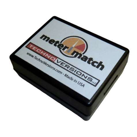
MeterMatch™ by TechnoVersions LLC is for making analog
gauges more accurate, or to allow you to mix and match
different gauges and senders. It can be used with many
gauges that have resistive senders - such as common fuel, oil-
pressure and temperature gauges.
The MeterMatch-VR, a special model, is designed to control
gauges in 60's-early 70's era Ford and Chrysler products which have gauges that are powered by a
5V instrument voltage regulator behind the instrument panel. MeterMatch-VR provides the circuitry to
improve the accuracy of the gauge, and also to power the gauge since the factory regulator isn't
compatible with modern electronics.
Note: If you are finding this small manual difficult to read, go to the TechnoVersions.com web site
where you will find this manual as a PDF, which you can view or print in larger size.
Wiring Quick-Start

- 2 -
Theory of Operation
MeterMatch-VR is wired between your sender (sensor) and your gauge. It reads the resistance of
the sender, then based on the calibration values, sends a signal to drive your gauge to the desired
reading. It treats the input and output entirely separately, so it doesn't care if the input to the gauge is
scaled differently than the sender, or even if the sender signal has a reversed sender signal than the
gauge - it can correct for that.
To calibrate MeterMatch-VR, you first set the sender to a known value. For example, fill your fuel
tank. Set the MeterMatch to program mode, then with Up and Dn buttons, make your gauge read
what you want for that sender value. When you are happy with that, press the Save button, and the
value is remembered in the MeterMatch. Do the same process with the sender reading a value near
the other end of its range, and you are done. MeterMatch interpolates from these values to make the
gauge read proportionately at values above, below, and between the calibration values. If you know
the resistance of your sender, you can also calibrate to common end-values of senders, even without
the sender being at that specific resistance.
The basic process of having the gauge read properly from calibration points near each end of the
range is fine for most applications, but you can be more sophisticated if you wish. For example, what
if your fuel tank is large at the bottom, and small at the top? In this case, it won't read properly
throughout the range. MeterMatch provides two additional calibration points between the end-points.
So, in this case, you could have an additional calibration point where the tank changes size. Another
use for these points would be if your tank is cylindrical (like a truck fuel tank) so the gauge is
inaccurate at both sides of center. Here, you can add additional calibration points (for example at
30% and 70%) and the accuracy is drastically improved.
Note that on some gauges, you may not be able to generate a completely full reading on the gauge,
but you should be able to get close. Empty readings are generally not an issue.

- 3 -
Installation
MeterMatch-VR is contained in a plastic enclosure that is 1.85" by 2.40" x 0.93". To calibrate it, you
will need to expose the circuit by removing the small Phillips-head screw in the bottom center of the
enclosure, using a #1 or smaller Phillips screwdriver. Take care that the circuit board doesn't touch
any metal which could short things out, and when finally installed, make sure it is in a dry spot that
doesn't get overly hot. MeterMatch generates some heat while in use.
Be careful when it is open and operating, the large voltage regulator inside (secured with hex-
screw) can get hot - don't burn yourself.

- 4 -
It is wired by connecting to the provided wires.
MeterMatch-VR requires the connection of five wires. The signals are:
Red +12V power. The red wire is connected to a 12V power
source that is powered only when the ignition is turned on.
Typically, this can be connected to the back of the ignition
switch on the accessories terminal.
Blue Signal from sender. The blue wire is connected to the signal
from the sender. This was previously connected to one side
of the gauge. If you aren't sure which wire it was,
disconnect them one at a time, and measure the voltage
with the ignition turned on. One of the wires will read about
5V (or a pulsing voltage), and the other will read zero volts -
that's the sender wire that you want. Connect it to the blue
wire from MeterMatch-VR.
White Signal to gauge. The white wire connects to the terminal on
the gauge that the factory sender previously connected to.
Orange +5V to power the gauge. The orange wire connects to the
side of the gauge that used to be connected to the car's 5V
power supply. Disconnect that wire from the gauge, and
leave it disconnected, it will no longer be used. In its place,
connect the orange wire from the MeterMatch-VR.
Black Ground. The black must be connected to a good ground.
Notes:
- The gauges installed in most early Ford/Chrysler products typically don't care if the two terminals
are reversed, both are isolated and polarity independent, but it's a good idea to connect them in the
same polarity (power and signal) as originally wired.
- Don't attempt to power more than one gauge from the orange wire from the MeterMatch-VR, it is
designed to only provide enough current for one gauge, and could otherwise overheat.
- MeterMatch-VR is provided with wires and terminals that are often used in this application, but yours
may be different. Don't hesitate to lengthen or shorten the wires or install your own terminals. If you
use the provided stainless 10-32 nuts on the back of your gauge, they may thread on with a little
difficulty since the threads on the post may be slightly deformed from the factory push-on connectors.
- Some gauges may be connected to a one-sided circuit board. In this case, you will need to isolate
the two terminals from the dash-board circuit PCB prior to connecting the MeterMatch.
TechnoVersions offers supply isolation, stepped washers for a low price.

- 5 -
Calibration
Once wired, it is necessary to calibrate your MeterMatch.
The rotary switch Ѳ positions are used as follows:
0 Normal Operation after calibration
1 High calibration point
2 Mid-high calibration point
3 Mid-low calibration point
4 Low calibration point
In addition to the terminal strip and rotary switch, you will find three push-buttons:
Up Moves the meter needle one direction
Dn Moves the meter needle the other direction
Save Stores the calibration point presently selected
Standard calibration process (sender resistance not known):
1. Set your sender to a point near one end of the value being measured (we'll start at the top in this
example, but order is unimportant).
2. Set the rotary switch Ѳ to position "1" (High Calibration Point). The LED in MeterMatch will light
up.
3. Use the Up/Dn buttons to make your gauge read the appropriate setting for the present sender
output. Depending on the gauge, the buttons may work backwards, but don't worry about that - just
make the gauge read the desired value. MeterMatch will work properly even if polarity is reversed
between the gauge and sender. Some meters are well-dampened so this process can take a little
time. Make a button press or two at a time and wait for the gauge to respond. It doesn't hurt to tap
lightly on the gauge too. There are several hundred increments, so it may take many button-presses.
4. Press the Save button to save this calibration point. The LED on MeterMatch will go out
momentarily to indicate that the value is being saved, and then turn back on.
Note: Calibration doesn't need to be done at the extreme high and low sensor points, but most
accuracy is achieved when near the limits of the readings.
Repeat these steps but with the sender set to a position for the other end of measurement, the rotary
switch Ѳ to "4" (Low Calibration Point), and then use the Up/Dn buttons until gauge is reading
appropriately, then press Save again.

- 6 -
Finally, set the MeterMatch rotary switch Ѳ back to "0" (Normal Operation), put the cover back on,
and enjoy using your calibrated gauge.
You can go back and reset any point using the same process, it will simply over-write the data for that
point stored previously. If you would like to erase a point (for example a point or limit you don't want
to use any more): with no power applied, set the rotary switch Ѳ to the position reflecting the point
you want to erase, hold down the Save button, then turn power on.
Note: After initial calibration, particularly for temperature gauges, it’s a good idea to check at least
one midpoint value to ensure that the reading is correct. If not, the sender and/or gauge may be non-
linear, leading to inaccuracy. In this case, accuracy can be enhanced by using one or more
additional calibration points.
Alternate calibration process (sender resistance known):
If you know the resistance of your sender, you can use that to help do calibration. You will need to
know the sender range (end-points) in Ohms. For example the sender might be 240 Ohms () when
the reading is low, and 33 Ohms when the reading is high. If you have this data, there are two ways
that you can use it for calibration:
Method 1: Connect a resistor (available at places such as Radio Shack) of the desired value on the
MeterMatch sender input pin (pin 3) to ground, then perform calibration at that point just as with the
standard calibration process previously shown.
Method 2: You can have MeterMatch calibrate to some internally stored resistance values. To use
these, do the following:
1. Power up MeterMatch
2. Set the rotary switch Ѳ to zero (normal operation)
3. Press and hold the Save button. The LED will illuminate.
4. While the Save button is being held down, press the Up button, the number of times shown in this
table. Each time you press the Up button the LED will blink the number of times that it has been
pressed. For example after you have pressed it twice, it will blink twice. You can start over at any
time by releasing the Save button.
Number of "Up" Button
Pushes
Sender Resistance Simulated
(Ohms)
1 0
2 10
3 33
4 73
5 90
6 180
7 240

- 7 -
5. Release the Save button, then use the standard calibration procedure (rotary switch Ѳ to which
point you are setting, Up/Dn buttons to make gauge read the desired setting, then Save). When the
Save button is pressed (and the rotary switch Ѳ is not set to 0), MeterMatch will use the resistance
value you just entered, and then reset itself to back normal operation (measuring the connected
sender resistance).
Calibration Checking and Enhancement
Feel free to use a combination of these calibration methods. For example, you might initially calibrate
to the published resistance values of your sender, then when the opportunity comes to improve
accuracy, recalibrate a point. Using the fuel gauge, for example, recalibrate the end-point when you
run out of gas, or fill up the tank. Whenever you return to a position of the rotary dial, you can over-
write the data that was previously programmed.
Return Policy
If a MeterMatch unit does not work properly in your application, and is not damaged, TechnoVersions
will allow return for full refund of purchase cost, exclusive of shipping charges. Claim for such must
occur within 30 days of product shipment from TechnoVersions. Ship the unit back to
TechnoVersions along with a description of the problem. TechnoVersions will remit the refund via US
Mail or PayPal (at TechnoVersions discretion) within 10 working days of product receipt.
Limited Warranty
TechnoVersions LLC provides a limited warranty for MeterMatch. If a unit should fail within 180 days
from time of shipment from TechnoVersions, it can be returned for repair or replacement at
TechnoVersions discretion. Products subject to abuse (as determined by TechnoVersions) are
excluded from this limited warranty. TechnoVersions LLC makes no other claims as to suitability and
excludes any liability for direct, indirect or consequential damages. Exclusive remedy is limited to
product replacement or repair. Cost of shipping the product to TechnoVersions is at the customer’s
expense, but the replacement/repaired MeterMatch will be shipped to customer via USPS or UPS
ground at TechnoVersions expense for domestic customers. When shipping out of the US,
TechnoVersions limits its shipping cost to that of US shipments, additional costs are the responsibility
of the customer. When returning MeterMatch to TechnoVersions, include a description of the fault to
help facilitate repair.

- 8 -
MeterMatchTM Specifications
(subject to change)
Size
1.85"x2.4"x0.93"
Weight
1.
5
Oz
Connections
#18 AWG wires, approximately
18" long
Sender Input
Ohmmeter reading of sender
input to ground
Max current/voltage through
sender 20mA/5Vdc
Resolution
ranges from
approximately 5% at 5 to 0.1%
at 3 K
Range 0-3,000
Gauge output
C
onstant
-
current sink
Full output range resolution
better than 1%, actual resolution
depends upon working range of
gauge
Input/Output Translation
Meter output current based on
linear interpolation of sender
resistance calibration points.
Four calibration points provided,
minimum of two necessary for
operation.
+5V Power Output
Up to 250mA
Controls
Up, Down, Save buttons
8
-
Position rotary
switch
(MeterMatchVR Instruction Manual - Rev11/2013)

MeterMatch-VR™
Overview
MeterMatch™ by TechnoVersions LLC is for making analog
gauges more accurate, or to allow you to mix and match
different gauges and senders. It can be used with many
gauges that have resistive senders - such as common fuel, oil-
pressure and temperature gauges.
The MeterMatch-VR, a special model, is designed to control
gauges in 60's-early 70's era Ford and Chrysler products which have gauges that are powered by a
5V instrument voltage regulator behind the instrument panel. MeterMatch-VR provides the circuitry to
improve the accuracy of the gauge, and also to power the gauge since the factory regulator isn't
compatible with modern electronics.
Note: If you are finding this small manual difficult to read, go to the TechnoVersions.com web site
where you will find this manual as a PDF, which you can view or print in larger size.
Wiring Quick-Start

- 2 -
Theory of Operation
MeterMatch-VR is wired between your sender (sensor) and your gauge. It reads the resistance of
the sender, then based on the calibration values, sends a signal to drive your gauge to the desired
reading. It treats the input and output entirely separately, so it doesn't care if the input to the gauge is
scaled differently than the sender, or even if the sender signal has a reversed sender signal than the
gauge - it can correct for that.
To calibrate MeterMatch-VR, you first set the sender to a known value. For example, fill your fuel
tank. Set the MeterMatch to program mode, then with Up and Dn buttons, make your gauge read
what you want for that sender value. When you are happy with that, press the Save button, and the
value is remembered in the MeterMatch. Do the same process with the sender reading a value near
the other end of its range, and you are done. MeterMatch interpolates from these values to make the
gauge read proportionately at values above, below, and between the calibration values. If you know
the resistance of your sender, you can also calibrate to common end-values of senders, even without
the sender being at that specific resistance.
The basic process of having the gauge read properly from calibration points near each end of the
range is fine for most applications, but you can be more sophisticated if you wish. For example, what
if your fuel tank is large at the bottom, and small at the top? In this case, it won't read properly
throughout the range. MeterMatch provides two additional calibration points between the end-points.
So, in this case, you could have an additional calibration point where the tank changes size. Another
use for these points would be if your tank is cylindrical (like a truck fuel tank) so the gauge is
inaccurate at both sides of center. Here, you can add additional calibration points (for example at
30% and 70%) and the accuracy is drastically improved.
Note that on some gauges, you may not be able to generate a completely full reading on the gauge,
but you should be able to get close. Empty readings are generally not an issue.

- 3 -
Installation
MeterMatch-VR is contained in a plastic enclosure that is 1.85" by 2.40" x 0.93". To calibrate it, you
will need to expose the circuit by removing the small Phillips-head screw in the bottom center of the
enclosure, using a #1 or smaller Phillips screwdriver. Take care that the circuit board doesn't touch
any metal which could short things out, and when finally installed, make sure it is in a dry spot that
doesn't get overly hot. MeterMatch generates some heat while in use.
Be careful when it is open and operating, the large voltage regulator inside (secured with hex-
screw) can get hot - don't burn yourself.

- 4 -
It is wired by connecting to the provided wires.
MeterMatch-VR requires the connection of five wires. The signals are:
Red +12V power. The red wire is connected to a 12V power
source that is powered only when the ignition is turned on.
Typically, this can be connected to the back of the ignition
switch on the accessories terminal.
Blue Signal from sender. The blue wire is connected to the signal
from the sender. This was previously connected to one side
of the gauge. If you aren't sure which wire it was,
disconnect them one at a time, and measure the voltage
with the ignition turned on. One of the wires will read about
5V (or a pulsing voltage), and the other will read zero volts -
that's the sender wire that you want. Connect it to the blue
wire from MeterMatch-VR.
White Signal to gauge. The white wire connects to the terminal on
the gauge that the factory sender previously connected to.
Orange +5V to power the gauge. The orange wire connects to the
side of the gauge that used to be connected to the car's 5V
power supply. Disconnect that wire from the gauge, and
leave it disconnected, it will no longer be used. In its place,
connect the orange wire from the MeterMatch-VR.
Black Ground. The black must be connected to a good ground.
Notes:
- The gauges installed in most early Ford/Chrysler products typically don't care if the two terminals
are reversed, both are isolated and polarity independent, but it's a good idea to connect them in the
same polarity (power and signal) as originally wired.
- Don't attempt to power more than one gauge from the orange wire from the MeterMatch-VR, it is
designed to only provide enough current for one gauge, and could otherwise overheat.
- MeterMatch-VR is provided with wires and terminals that are often used in this application, but yours
may be different. Don't hesitate to lengthen or shorten the wires or install your own terminals. If you
use the provided stainless 10-32 nuts on the back of your gauge, they may thread on with a little
difficulty since the threads on the post may be slightly deformed from the factory push-on connectors.
- Some gauges may be connected to a one-sided circuit board. In this case, you will need to isolate
the two terminals from the dash-board circuit PCB prior to connecting the MeterMatch.
TechnoVersions offers supply isolation, stepped washers for a low price.

- 5 -
Calibration
Once wired, it is necessary to calibrate your MeterMatch.
The rotary switch Ѳ positions are used as follows:
0 Normal Operation after calibration
1 High calibration point
2 Mid-high calibration point
3 Mid-low calibration point
4 Low calibration point
In addition to the terminal strip and rotary switch, you will find three push-buttons:
Up Moves the meter needle one direction
Dn Moves the meter needle the other direction
Save Stores the calibration point presently selected
Standard calibration process (sender resistance not known):
1. Set your sender to a point near one end of the value being measured (we'll start at the top in this
example, but order is unimportant).
2. Set the rotary switch Ѳ to position "1" (High Calibration Point). The LED in MeterMatch will light
up.
3. Use the Up/Dn buttons to make your gauge read the appropriate setting for the present sender
output. Depending on the gauge, the buttons may work backwards, but don't worry about that - just
make the gauge read the desired value. MeterMatch will work properly even if polarity is reversed
between the gauge and sender. Some meters are well-dampened so this process can take a little
time. Make a button press or two at a time and wait for the gauge to respond. It doesn't hurt to tap
lightly on the gauge too. There are several hundred increments, so it may take many button-presses.
4. Press the Save button to save this calibration point. The LED on MeterMatch will go out
momentarily to indicate that the value is being saved, and then turn back on.
Note: Calibration doesn't need to be done at the extreme high and low sensor points, but most
accuracy is achieved when near the limits of the readings.
Repeat these steps but with the sender set to a position for the other end of measurement, the rotary
switch Ѳ to "4" (Low Calibration Point), and then use the Up/Dn buttons until gauge is reading
appropriately, then press Save again.

- 6 -
Finally, set the MeterMatch rotary switch Ѳ back to "0" (Normal Operation), put the cover back on,
and enjoy using your calibrated gauge.
You can go back and reset any point using the same process, it will simply over-write the data for that
point stored previously. If you would like to erase a point (for example a point or limit you don't want
to use any more): with no power applied, set the rotary switch Ѳ to the position reflecting the point
you want to erase, hold down the Save button, then turn power on.
Note: After initial calibration, particularly for temperature gauges, it’s a good idea to check at least
one midpoint value to ensure that the reading is correct. If not, the sender and/or gauge may be non-
linear, leading to inaccuracy. In this case, accuracy can be enhanced by using one or more
additional calibration points.
Alternate calibration process (sender resistance known):
If you know the resistance of your sender, you can use that to help do calibration. You will need to
know the sender range (end-points) in Ohms. For example the sender might be 240 Ohms () when
the reading is low, and 33 Ohms when the reading is high. If you have this data, there are two ways
that you can use it for calibration:
Method 1: Connect a resistor (available at places such as Radio Shack) of the desired value on the
MeterMatch sender input pin (pin 3) to ground, then perform calibration at that point just as with the
standard calibration process previously shown.
Method 2: You can have MeterMatch calibrate to some internally stored resistance values. To use
these, do the following:
1. Power up MeterMatch
2. Set the rotary switch Ѳ to zero (normal operation)
3. Press and hold the Save button. The LED will illuminate.
4. While the Save button is being held down, press the Up button, the number of times shown in this
table. Each time you press the Up button the LED will blink the number of times that it has been
pressed. For example after you have pressed it twice, it will blink twice. You can start over at any
time by releasing the Save button.
Number of "Up" Button
Pushes
Sender Resistance Simulated
(Ohms)
1 0
2 10
3 33
4 73
5 90
6 180
7 240

- 7 -
5. Release the Save button, then use the standard calibration procedure (rotary switch Ѳ to which
point you are setting, Up/Dn buttons to make gauge read the desired setting, then Save). When the
Save button is pressed (and the rotary switch Ѳ is not set to 0), MeterMatch will use the resistance
value you just entered, and then reset itself to back normal operation (measuring the connected
sender resistance).
Calibration Checking and Enhancement
Feel free to use a combination of these calibration methods. For example, you might initially calibrate
to the published resistance values of your sender, then when the opportunity comes to improve
accuracy, recalibrate a point. Using the fuel gauge, for example, recalibrate the end-point when you
run out of gas, or fill up the tank. Whenever you return to a position of the rotary dial, you can over-
write the data that was previously programmed.
Return Policy
If a MeterMatch unit does not work properly in your application, and is not damaged, TechnoVersions
will allow return for full refund of purchase cost, exclusive of shipping charges. Claim for such must
occur within 30 days of product shipment from TechnoVersions. Ship the unit back to
TechnoVersions along with a description of the problem. TechnoVersions will remit the refund via US
Mail or PayPal (at TechnoVersions discretion) within 10 working days of product receipt.
Limited Warranty
TechnoVersions LLC provides a limited warranty for MeterMatch. If a unit should fail within 180 days
from time of shipment from TechnoVersions, it can be returned for repair or replacement at
TechnoVersions discretion. Products subject to abuse (as determined by TechnoVersions) are
excluded from this limited warranty. TechnoVersions LLC makes no other claims as to suitability and
excludes any liability for direct, indirect or consequential damages. Exclusive remedy is limited to
product replacement or repair. Cost of shipping the product to TechnoVersions is at the customer’s
expense, but the replacement/repaired MeterMatch will be shipped to customer via USPS or UPS
ground at TechnoVersions expense for domestic customers. When shipping out of the US,
TechnoVersions limits its shipping cost to that of US shipments, additional costs are the responsibility
of the customer. When returning MeterMatch to TechnoVersions, include a description of the fault to
help facilitate repair.

- 8 -
MeterMatchTM Specifications
(subject to change)
Size
1.85"x2.4"x0.93"
Weight
1.
5
Oz
Connections
#18 AWG wires, approximately
18" long
Sender Input
Ohmmeter reading of sender
input to ground
Max current/voltage through
sender 20mA/5Vdc
Resolution
ranges from
approximately 5% at 5 to 0.1%
at 3 K
Range 0-3,000
Gauge output
C
onstant
-
current sink
Full output range resolution
better than 1%, actual resolution
depends upon working range of
gauge
Input/Output Translation
Meter output current based on
linear interpolation of sender
resistance calibration points.
Four calibration points provided,
minimum of two necessary for
operation.
+5V Power Output
Up to 250mA
Controls
Up, Down, Save buttons
8
-
Position rotary
switch
(MeterMatchVR Instruction Manual - Rev11/2013)

MeterMatch-VR™
Overview
MeterMatch™ by TechnoVersions LLC is for making analog
gauges more accurate, or to allow you to mix and match
different gauges and senders. It can be used with many
gauges that have resistive senders - such as common fuel, oil-
pressure and temperature gauges.
The MeterMatch-VR, a special model, is designed to control
gauges in 60's-early 70's era Ford and Chrysler products which have gauges that are powered by a
5V instrument voltage regulator behind the instrument panel. MeterMatch-VR provides the circuitry to
improve the accuracy of the gauge, and also to power the gauge since the factory regulator isn't
compatible with modern electronics.
Note: If you are finding this small manual difficult to read, go to the TechnoVersions.com web site
where you will find this manual as a PDF, which you can view or print in larger size.
Wiring Quick-Start

- 2 -
Theory of Operation
MeterMatch-VR is wired between your sender (sensor) and your gauge. It reads the resistance of
the sender, then based on the calibration values, sends a signal to drive your gauge to the desired
reading. It treats the input and output entirely separately, so it doesn't care if the input to the gauge is
scaled differently than the sender, or even if the sender signal has a reversed sender signal than the
gauge - it can correct for that.
To calibrate MeterMatch-VR, you first set the sender to a known value. For example, fill your fuel
tank. Set the MeterMatch to program mode, then with Up and Dn buttons, make your gauge read
what you want for that sender value. When you are happy with that, press the Save button, and the
value is remembered in the MeterMatch. Do the same process with the sender reading a value near
the other end of its range, and you are done. MeterMatch interpolates from these values to make the
gauge read proportionately at values above, below, and between the calibration values. If you know
the resistance of your sender, you can also calibrate to common end-values of senders, even without
the sender being at that specific resistance.
The basic process of having the gauge read properly from calibration points near each end of the
range is fine for most applications, but you can be more sophisticated if you wish. For example, what
if your fuel tank is large at the bottom, and small at the top? In this case, it won't read properly
throughout the range. MeterMatch provides two additional calibration points between the end-points.
So, in this case, you could have an additional calibration point where the tank changes size. Another
use for these points would be if your tank is cylindrical (like a truck fuel tank) so the gauge is
inaccurate at both sides of center. Here, you can add additional calibration points (for example at
30% and 70%) and the accuracy is drastically improved.
Note that on some gauges, you may not be able to generate a completely full reading on the gauge,
but you should be able to get close. Empty readings are generally not an issue.

- 3 -
Installation
MeterMatch-VR is contained in a plastic enclosure that is 1.85" by 2.40" x 0.93". To calibrate it, you
will need to expose the circuit by removing the small Phillips-head screw in the bottom center of the
enclosure, using a #1 or smaller Phillips screwdriver. Take care that the circuit board doesn't touch
any metal which could short things out, and when finally installed, make sure it is in a dry spot that
doesn't get overly hot. MeterMatch generates some heat while in use.
Be careful when it is open and operating, the large voltage regulator inside (secured with hex-
screw) can get hot - don't burn yourself.

- 4 -
It is wired by connecting to the provided wires.
MeterMatch-VR requires the connection of five wires. The signals are:
Red +12V power. The red wire is connected to a 12V power
source that is powered only when the ignition is turned on.
Typically, this can be connected to the back of the ignition
switch on the accessories terminal.
Blue Signal from sender. The blue wire is connected to the signal
from the sender. This was previously connected to one side
of the gauge. If you aren't sure which wire it was,
disconnect them one at a time, and measure the voltage
with the ignition turned on. One of the wires will read about
5V (or a pulsing voltage), and the other will read zero volts -
that's the sender wire that you want. Connect it to the blue
wire from MeterMatch-VR.
White Signal to gauge. The white wire connects to the terminal on
the gauge that the factory sender previously connected to.
Orange +5V to power the gauge. The orange wire connects to the
side of the gauge that used to be connected to the car's 5V
power supply. Disconnect that wire from the gauge, and
leave it disconnected, it will no longer be used. In its place,
connect the orange wire from the MeterMatch-VR.
Black Ground. The black must be connected to a good ground.
Notes:
- The gauges installed in most early Ford/Chrysler products typically don't care if the two terminals
are reversed, both are isolated and polarity independent, but it's a good idea to connect them in the
same polarity (power and signal) as originally wired.
- Don't attempt to power more than one gauge from the orange wire from the MeterMatch-VR, it is
designed to only provide enough current for one gauge, and could otherwise overheat.
- MeterMatch-VR is provided with wires and terminals that are often used in this application, but yours
may be different. Don't hesitate to lengthen or shorten the wires or install your own terminals. If you
use the provided stainless 10-32 nuts on the back of your gauge, they may thread on with a little
difficulty since the threads on the post may be slightly deformed from the factory push-on connectors.
- Some gauges may be connected to a one-sided circuit board. In this case, you will need to isolate
the two terminals from the dash-board circuit PCB prior to connecting the MeterMatch.
TechnoVersions offers supply isolation, stepped washers for a low price.
Table of contents
Other TechnoVersions Measuring Instrument manuals
Popular Measuring Instrument manuals by other brands

Emerson
Emerson 755A instruction manual

Bushnell
Bushnell YARDAGE PRO SPORT 450 owner's manual
Myron L
Myron L D -1 operating instructions
Crevavi
Crevavi Konnect-Wi Quick reference guide
BGS technic
BGS technic 3532 quick start guide
Precision Digital Corporation
Precision Digital Corporation ProtEX-MAX PD8-6200 Series instruction manual
