TechnoVersions MeterMatch User manual

MeterMatch™
Overview
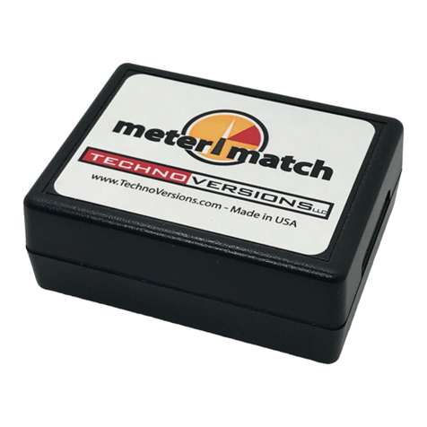
MeterMatch™ by TechnoVersions LLC is for making analog
gauges more accurate, or to allow you to mix and match
different gauges and senders. It can be used with many
gauges that have resistive senders - such as common fuel, oil-
pressure and temperature gauges. In addition, it allows you to
have low and/or high set-points that will trigger a bright, blinking
LED indicator to alert if the gauge exceeds normal values.
Note: If you are having trouble reading the small print of this instruction manual, go to the
TechnoVersions website and open the on-line copy. You can print it out full size.
Theory of Operation
MeterMatch is wired between your sender (sensor) and your gauge. It reads the resistance of the
sender, then based on the calibration values, sends a signal to drive your gauge to the desired
reading. It treats the input and output entirely separately, so it doesn't care if the input to the gauge is
scaled differently than the sender, or even if the sender signal has a reversed sender signal than the
gauge - it can correct for that.
To calibrate MeterMatch, you first set the sender to a known value. For example, fill your fuel tank.
Set the MeterMatch to program mode, then with Up and Dn buttons, make your gauge read what you
want for that sender value. When you are happy with that, press the Save button, and the value is
remembered in the MeterMatch. Do the same process with the sender reading a value near the other

- 2 -
end of its range, and you are done. MeterMatch interpolates from these values to make the gauge
read proportionately at values above, below, and between the calibration values. If you know the
resistance of your sender, you can also calibrate to common end-values of senders, even without the
sender being at that specific resistance.
The basic process of having the gauge read properly from calibration points near each end of the
range is fine for most applications, but you can be more sophisticated if you wish. For example, what
if your fuel tank is large at the bottom, and small at the top? In this case, it won't read properly
throughout the range. MeterMatch provides two additional calibration points between the endpoints.
So, in this case, you could have an additional calibration point where the tank changes size. Another
use for these points would be if your tank is cylindrical (like a truck fuel tank) so the gauge is
inaccurate at both sides of center. Here, you can add additional calibration points (for example at
30% and 70%) and the accuracy is drastically improved
Optional Alarm Indicator
MeterMatch allows you to set a lower and higher alarm set-point. These are
set just like the calibration points (you use the Up/Dn buttons to set the
gauge to the point at which the alarm happens), but instead of affecting the
meter reading, they set a signal to turn on an optional LED. This bright LED
is programmed to flash, and can be mounted near the meter to alert the
driver to take a look at the gauge. You can use none, either, or both set-
points.

- 3 -
Installation
MeterMatch is contained in a plastic enclosure that is 1.85" by 2.4" x .93". To install and calibrate it,
you will need to expose the circuit by removing the small Phillips-head screw in the bottom center of
the enclosure. Use a #1 or smaller Phillips screwdriver. Take care that the circuit board doesn't
touch any metal which could short things out, and when finally installed, make sure it is in a dry spot
that doesn't get overly hot.
It is wired by connecting to a screw-terminal strip inside. You will need a small straight-blade
screwdriver (tip width less than .11"). It accommodates wire sizes from #16 AWG to #28 AWG.
Wires on the larger end of this range, for example #18 AWG, are recommended.
MeterMatch only requires four wires, and all these signals are usually available near the back of the
gauge. The signals are:
Pin 1 +12V (switched by ignition)
Pin 2 Input signal to gauge (output from MeterMarch)
Pin 3 Output signal from sender (input to MeterMatch)
Pin 6 Ground

- 4 -
Calibration
Once wired, it is necessary to calibrate your MeterMatch.
The rotary switch Ѳ positions are used as follows:
0 Normal Operation after calibration
1 High calibration point
2 Mid-high calibration point
3 Mid-low calibration point
4 Low calibration point
5 Alarm high calibration point
6 Alarm low calibration point
In addition to the terminal strip and rotary switch, you will find three push-buttons:
Up Moves the meter needle one direction
Dn Moves the meter needle the other direction
Save Stores the calibration point presently selected
Standard calibration process (sender resistance not known):
1. Set your sender to a point near one end of the value being measured (we'll start at the top in this
example, but order is unimportant).
2. Set the rotary switch Ѳ to position "1" (High Calibration Point). The LED in MeterMatch will light
up.
3. Use the Up/Dn buttons to make your gauge read the appropriate setting for the present sender
output. Depending on the gauge, the buttons may work backwards, but don't worry about that - just
make the gauge read the desired value. MeterMatch will work properly even if polarity is reversed
between the gauge and sender. Some meters are well-dampened so this process can take a little
time. It doesn't hurt to tap lightly on the gauge too.
4. Press the Save button to save this calibration point. The LED on MeterMatch will go out
momentarily to indicate that the value is being saved, and then turn back on.
Note: Calibration doesn't need to be done at the extreme high and low sensor points, but most
accuracy is achieved when near the limits of the readings.
Repeat these steps but with the sender set to a position for the other end of measurement, the rotary
switch Ѳ to "4" (Low Calibration Point), and then use the Up/Dn buttons until gauge is reading
appropriately, then press Save again.

- 5 -
Finally, set the MeterMatch rotary switch Ѳ back to "0" (Normal Operation), put the cover back on,
and enjoy using your calibrated gauge.
Resetting the MeterMatch:
You can go back and reset any point using the same process, it will simply over-write the data for that
point stored previously. If you would like to erase a point (for example a point or limit you don't want
to use any more): with no power applied, set the rotary switch Ѳ to the position reflecting the point
you want to erase, hold down the Save button, then turn power on. If you want to reset the
MeterMatch to factory settings: with no power applied, set the rotary switch Ѳ to position 0, hold
down the Save button, then turn power on.
Alternate calibration process (sender resistance known):
If you know the resistance of your sender, you can use that to help do calibration. You will need to
know the sender range (end-points) in Ohms. For example the sender might be 240 Ohms () when
the reading is low, and 33 Ohms when the reading is high. If you have this data, there are two ways
that you can use it for calibration:
Method 1: Connect a resistor (available at places such as Radio Shack) of the desired value on the
MeterMatch sender input pin (pin 3) to ground, and then perform calibration at that point just as with
the standard calibration process previously shown.
Method 2: You can have MeterMatch calibrate to some internally stored resistance values. To use
these, do the following:
1. Power up MeterMatch
2. Set the rotary switch Ѳ to zero (normal operation)
3. Press and hold the Save button. The LED will illuminate.
4. While the Save button is being held down, press the Up button, the number of times shown in this
table. Each time you press the Up button the LED will blink the number of times that it has been
pressed. For example after you have pressed it twice, it will blink twice. Wait each time for the
blinking to occur. You can start over at any time by releasing the Save button.
Number of "Up" Button
Pushes
Sender Resistance Simulated
(Ohms)
1 0
2 10
3 33
4 73
5 90
6 180
7 240

- 6 -
5. Release the Save button, then use the standard calibration procedure (rotary switch Ѳ to which
point you are setting, Up/Dn buttons to make gauge read the desired setting, then Save). When the
Save button is pressed (and the rotary switch Ѳ is not set to 0), MeterMatch will use the resistance
value you just entered, and then reset itself to back normal operation (measuring the connected
sender resistance).
Calibration Checking and Enhancement
Feel free to use a combination of these calibration methods. For example, you might initially calibrate
to the published resistance values of your sender, then when the opportunity comes to improve
accuracy, recalibrate a point. Using the fuel gauge, for example, recalibrate the end-point when you
run out of gas, or fill up the tank. Whenever you return to a position of the rotary dial, you can over-
write the data that was previously programmed.
Voltage Correction
Most gauges are connected to a voltage regulator in the instrument wiring so that they get a constant
voltage whether the engine is running or not. However, if this is not the case, when you calibrate your
gauge at one voltage (for example, engine not running, battery at +12.5V), when you start the vehicle
and the voltage rises (for example to +13.8V), the gauge reading might change significantly. If you
run into this, MeterMatch has an automatic voltage correction feature that corrects the reading for
different voltages. To enable this feature: (a) remove power from the MeterMatch, (b) set the rotary
switch Ѳ to position "0" (normal operating), then (c) press and hold the Up button while applying
power to the MeterMatch. Hold it for at least a second after power is applied. MeterMatch will
remember this setting in future use. If you wish to remove the voltage correction feature, repeat the
same process, but hold the Dn button rather than the Up button. Note that if you change this setting,
the gauge will need to be recalibrated with the new setting.
Installing/Programming the Alarm Indicator
The optional LED Alarm Indicator can be mounted near the gauge being controlled.
The LED is installed by drilling a 9/16" hole in the instrument panel. 12" leads are then wired to the
terminal strip in the MeterMatch. Be careful when installing the LED since the leads are not
particularly strong, and can be pulled loose from the LED. The darker of the two wires (cathode
lead) coming from the LED is installed in terminal strip pin 4, and the lighter-colored wire (anode side)
is connected to pin 5. It won't hurt anything if you accidently reverse these wires, but the LED won't
light.
Pin 4 LED negative (cathode)
Pin 5 LED positive (anode)
You can program the upper and lower alarm points with rotary switch Ѳ positions 5 and 6
respectively. Set the rotary switch Ѳ , use the Up/Dn buttons to set the desired gauge reading at

- 7 -
the set-point, then press Save. MeterMatch doesn't care what value the sender is at while
programming the alarm points - it is only interested in what you make the gauge read with the Up/Dn
buttons. As a result, ensure that you have calibrated your gauge accurately (rotary switch Ѳ
positions 1-4), or your alarm will not be accurate either.
These points can also be erased using the same procedure as normal cal points. Depending on how
your gauge works, you may find that the low and high alarm set-points are reversed in operation from
what you expect. If that's the case, simply reverse the calibration (use high for low and vice-versa).
If you have more than one MeterMatch installed, you can logic "or" the LED signals so that if any of
the alarm signals become true, they will set off a single LED. Simply connect the LED positive
(anode) to any one of the MeterMatch circuits, and then connect all of the MeterMatch LED negative
(cathode) wires to the LED negative side wire.
Return Policy
If a MeterMatch unit does not work properly in your application, and is not damaged, TechnoVersions
will allow return for full refund of purchase cost, exclusive of shipping charges. Claim for such must
occur within 30 days of product shipment from TechnoVersions. Ship the unit back to
TechnoVersions along with a description of the problem and proof of purchase. TechnoVersions will
remit the refund via US Mail or PayPal (at TechnoVersions discretion) within 10 working days of
product receipt.
Limited Warranty
TechnoVersions LLC provides a limited warranty for MeterMatch. If a unit should fail within 180 days
from time of shipment from TechnoVersions, it can be returned for repair or replacement at
TechnoVersions discretion. Products subject to abuse (as determined by TechnoVersions) are
excluded from this limited warranty. TechnoVersions LLC makes no other claims as to suitability and
excludes any liability for direct, indirect or consequential damages. Exclusive remedy is limited to
product replacement or repair. Cost of shipping the product to TechnoVersions is at the customer’s
expense, but the replacement/repaired MeterMatch will be shipped to customer via USPS or UPS
ground at TechnoVersions expense, except for shipments out of the US, in which case
TechnoVersions shipping cost is limited to the cost of domestic shipments. When returning
MeterMatch to TechnoVersions, include a description of the fault to help facilitate repair.

- 8 -
MeterMatchTM Specifications
Size
1.85"x2.4"x0.93"
Weight
1.2 Oz
Connections
1x6 screw terminal strip
accepting #16-#28 AWG wires
Sender Input
Ohmmeter reading of sender
input to ground
Max current/voltage through
sender 20mA/5Vdc
Resolution approximately 1
for readings less than 100 .
Range 0-3,000
Gauge output
C
onstant
-
current sink
Full output range resolution
better than 1%, actual resolution
depends upon working range of
gauge
Input/Output Translation
Meter output current based on
linear interpolation of sender
resistance calibration points.
Four calibration points provided,
minimum of two necessary for
operation.
LED Output
Programmed blinking
Source impedance to anode
400, open-collector to
cathode
Controls
Up, Down, Save buttons
8
-
Position rotary switch
(MeterMatch Instruction Manual - Rev 6/2017)

MeterMatch™
Overview
MeterMatch™ by TechnoVersions LLC is for making analog
gauges more accurate, or to allow you to mix and match
different gauges and senders. It can be used with many
gauges that have resistive senders - such as common fuel, oil-
pressure and temperature gauges. In addition, it allows you to
have low and/or high set-points that will trigger a bright, blinking
LED indicator to alert if the gauge exceeds normal values.
Note: If you are having trouble reading the small print of this instruction manual, go to the
TechnoVersions website and open the on-line copy. You can print it out full size.
Theory of Operation
MeterMatch is wired between your sender (sensor) and your gauge. It reads the resistance of the
sender, then based on the calibration values, sends a signal to drive your gauge to the desired
reading. It treats the input and output entirely separately, so it doesn't care if the input to the gauge is
scaled differently than the sender, or even if the sender signal has a reversed sender signal than the
gauge - it can correct for that.
To calibrate MeterMatch, you first set the sender to a known value. For example, fill your fuel tank.
Set the MeterMatch to program mode, then with Up and Dn buttons, make your gauge read what you
want for that sender value. When you are happy with that, press the Save button, and the value is
remembered in the MeterMatch. Do the same process with the sender reading a value near the other

- 2 -
end of its range, and you are done. MeterMatch interpolates from these values to make the gauge
read proportionately at values above, below, and between the calibration values. If you know the
resistance of your sender, you can also calibrate to common end-values of senders, even without the
sender being at that specific resistance.
The basic process of having the gauge read properly from calibration points near each end of the
range is fine for most applications, but you can be more sophisticated if you wish. For example, what
if your fuel tank is large at the bottom, and small at the top? In this case, it won't read properly
throughout the range. MeterMatch provides two additional calibration points between the endpoints.
So, in this case, you could have an additional calibration point where the tank changes size. Another
use for these points would be if your tank is cylindrical (like a truck fuel tank) so the gauge is
inaccurate at both sides of center. Here, you can add additional calibration points (for example at
30% and 70%) and the accuracy is drastically improved
Optional Alarm Indicator
MeterMatch allows you to set a lower and higher alarm set-point. These are
set just like the calibration points (you use the Up/Dn buttons to set the
gauge to the point at which the alarm happens), but instead of affecting the
meter reading, they set a signal to turn on an optional LED. This bright LED
is programmed to flash, and can be mounted near the meter to alert the
driver to take a look at the gauge. You can use none, either, or both set-
points.

- 3 -
Installation
MeterMatch is contained in a plastic enclosure that is 1.85" by 2.4" x .93". To install and calibrate it,
you will need to expose the circuit by removing the small Phillips-head screw in the bottom center of
the enclosure. Use a #1 or smaller Phillips screwdriver. Take care that the circuit board doesn't
touch any metal which could short things out, and when finally installed, make sure it is in a dry spot
that doesn't get overly hot.
It is wired by connecting to a screw-terminal strip inside. You will need a small straight-blade
screwdriver (tip width less than .11"). It accommodates wire sizes from #16 AWG to #28 AWG.
Wires on the larger end of this range, for example #18 AWG, are recommended.
MeterMatch only requires four wires, and all these signals are usually available near the back of the
gauge. The signals are:
Pin 1 +12V (switched by ignition)
Pin 2 Input signal to gauge (output from MeterMarch)
Pin 3 Output signal from sender (input to MeterMatch)
Pin 6 Ground

- 4 -
Calibration
Once wired, it is necessary to calibrate your MeterMatch.
The rotary switch Ѳ positions are used as follows:
0 Normal Operation after calibration
1 High calibration point
2 Mid-high calibration point
3 Mid-low calibration point
4 Low calibration point
5 Alarm high calibration point
6 Alarm low calibration point
In addition to the terminal strip and rotary switch, you will find three push-buttons:
Up Moves the meter needle one direction
Dn Moves the meter needle the other direction
Save Stores the calibration point presently selected
Standard calibration process (sender resistance not known):
1. Set your sender to a point near one end of the value being measured (we'll start at the top in this
example, but order is unimportant).
2. Set the rotary switch Ѳ to position "1" (High Calibration Point). The LED in MeterMatch will light
up.
3. Use the Up/Dn buttons to make your gauge read the appropriate setting for the present sender
output. Depending on the gauge, the buttons may work backwards, but don't worry about that - just
make the gauge read the desired value. MeterMatch will work properly even if polarity is reversed
between the gauge and sender. Some meters are well-dampened so this process can take a little
time. It doesn't hurt to tap lightly on the gauge too.
4. Press the Save button to save this calibration point. The LED on MeterMatch will go out
momentarily to indicate that the value is being saved, and then turn back on.
Note: Calibration doesn't need to be done at the extreme high and low sensor points, but most
accuracy is achieved when near the limits of the readings.
Repeat these steps but with the sender set to a position for the other end of measurement, the rotary
switch Ѳ to "4" (Low Calibration Point), and then use the Up/Dn buttons until gauge is reading
appropriately, then press Save again.

- 5 -
Finally, set the MeterMatch rotary switch Ѳ back to "0" (Normal Operation), put the cover back on,
and enjoy using your calibrated gauge.
Resetting the MeterMatch:
You can go back and reset any point using the same process, it will simply over-write the data for that
point stored previously. If you would like to erase a point (for example a point or limit you don't want
to use any more): with no power applied, set the rotary switch Ѳ to the position reflecting the point
you want to erase, hold down the Save button, then turn power on. If you want to reset the
MeterMatch to factory settings: with no power applied, set the rotary switch Ѳ to position 0, hold
down the Save button, then turn power on.
Alternate calibration process (sender resistance known):
If you know the resistance of your sender, you can use that to help do calibration. You will need to
know the sender range (end-points) in Ohms. For example the sender might be 240 Ohms () when
the reading is low, and 33 Ohms when the reading is high. If you have this data, there are two ways
that you can use it for calibration:
Method 1: Connect a resistor (available at places such as Radio Shack) of the desired value on the
MeterMatch sender input pin (pin 3) to ground, and then perform calibration at that point just as with
the standard calibration process previously shown.
Method 2: You can have MeterMatch calibrate to some internally stored resistance values. To use
these, do the following:
1. Power up MeterMatch
2. Set the rotary switch Ѳ to zero (normal operation)
3. Press and hold the Save button. The LED will illuminate.
4. While the Save button is being held down, press the Up button, the number of times shown in this
table. Each time you press the Up button the LED will blink the number of times that it has been
pressed. For example after you have pressed it twice, it will blink twice. Wait each time for the
blinking to occur. You can start over at any time by releasing the Save button.
Number of "Up" Button
Pushes
Sender Resistance Simulated
(Ohms)
1 0
2 10
3 33
4 73
5 90
6 180
7 240

- 6 -
5. Release the Save button, then use the standard calibration procedure (rotary switch Ѳ to which
point you are setting, Up/Dn buttons to make gauge read the desired setting, then Save). When the
Save button is pressed (and the rotary switch Ѳ is not set to 0), MeterMatch will use the resistance
value you just entered, and then reset itself to back normal operation (measuring the connected
sender resistance).
Calibration Checking and Enhancement
Feel free to use a combination of these calibration methods. For example, you might initially calibrate
to the published resistance values of your sender, then when the opportunity comes to improve
accuracy, recalibrate a point. Using the fuel gauge, for example, recalibrate the end-point when you
run out of gas, or fill up the tank. Whenever you return to a position of the rotary dial, you can over-
write the data that was previously programmed.
Voltage Correction
Most gauges are connected to a voltage regulator in the instrument wiring so that they get a constant
voltage whether the engine is running or not. However, if this is not the case, when you calibrate your
gauge at one voltage (for example, engine not running, battery at +12.5V), when you start the vehicle
and the voltage rises (for example to +13.8V), the gauge reading might change significantly. If you
run into this, MeterMatch has an automatic voltage correction feature that corrects the reading for
different voltages. To enable this feature: (a) remove power from the MeterMatch, (b) set the rotary
switch Ѳ to position "0" (normal operating), then (c) press and hold the Up button while applying
power to the MeterMatch. Hold it for at least a second after power is applied. MeterMatch will
remember this setting in future use. If you wish to remove the voltage correction feature, repeat the
same process, but hold the Dn button rather than the Up button. Note that if you change this setting,
the gauge will need to be recalibrated with the new setting.
Installing/Programming the Alarm Indicator
The optional LED Alarm Indicator can be mounted near the gauge being controlled.
The LED is installed by drilling a 9/16" hole in the instrument panel. 12" leads are then wired to the
terminal strip in the MeterMatch. Be careful when installing the LED since the leads are not
particularly strong, and can be pulled loose from the LED. The darker of the two wires (cathode
lead) coming from the LED is installed in terminal strip pin 4, and the lighter-colored wire (anode side)
is connected to pin 5. It won't hurt anything if you accidently reverse these wires, but the LED won't
light.
Pin 4 LED negative (cathode)
Pin 5 LED positive (anode)
You can program the upper and lower alarm points with rotary switch Ѳ positions 5 and 6
respectively. Set the rotary switch Ѳ , use the Up/Dn buttons to set the desired gauge reading at

- 7 -
the set-point, then press Save. MeterMatch doesn't care what value the sender is at while
programming the alarm points - it is only interested in what you make the gauge read with the Up/Dn
buttons. As a result, ensure that you have calibrated your gauge accurately (rotary switch Ѳ
positions 1-4), or your alarm will not be accurate either.
These points can also be erased using the same procedure as normal cal points. Depending on how
your gauge works, you may find that the low and high alarm set-points are reversed in operation from
what you expect. If that's the case, simply reverse the calibration (use high for low and vice-versa).
If you have more than one MeterMatch installed, you can logic "or" the LED signals so that if any of
the alarm signals become true, they will set off a single LED. Simply connect the LED positive
(anode) to any one of the MeterMatch circuits, and then connect all of the MeterMatch LED negative
(cathode) wires to the LED negative side wire.
Return Policy
If a MeterMatch unit does not work properly in your application, and is not damaged, TechnoVersions
will allow return for full refund of purchase cost, exclusive of shipping charges. Claim for such must
occur within 30 days of product shipment from TechnoVersions. Ship the unit back to
TechnoVersions along with a description of the problem and proof of purchase. TechnoVersions will
remit the refund via US Mail or PayPal (at TechnoVersions discretion) within 10 working days of
product receipt.
Limited Warranty
TechnoVersions LLC provides a limited warranty for MeterMatch. If a unit should fail within 180 days
from time of shipment from TechnoVersions, it can be returned for repair or replacement at
TechnoVersions discretion. Products subject to abuse (as determined by TechnoVersions) are
excluded from this limited warranty. TechnoVersions LLC makes no other claims as to suitability and
excludes any liability for direct, indirect or consequential damages. Exclusive remedy is limited to
product replacement or repair. Cost of shipping the product to TechnoVersions is at the customer’s
expense, but the replacement/repaired MeterMatch will be shipped to customer via USPS or UPS
ground at TechnoVersions expense, except for shipments out of the US, in which case
TechnoVersions shipping cost is limited to the cost of domestic shipments. When returning
MeterMatch to TechnoVersions, include a description of the fault to help facilitate repair.

- 8 -
MeterMatchTM Specifications
Size
1.85"x2.4"x0.93"
Weight
1.2 Oz
Connections
1x6 screw terminal strip
accepting #16-#28 AWG wires
Sender Input
Ohmmeter reading of sender
input to ground
Max current/voltage through
sender 20mA/5Vdc
Resolution approximately 1
for readings less than 100 .
Range 0-3,000
Gauge output
C
onstant
-
current sink
Full output range resolution
better than 1%, actual resolution
depends upon working range of
gauge
Input/Output Translation
Meter output current based on
linear interpolation of sender
resistance calibration points.
Four calibration points provided,
minimum of two necessary for
operation.
LED Output
Programmed blinking
Source impedance to anode
400, open-collector to
cathode
Controls
Up, Down, Save buttons
8
-
Position rotary switch
(MeterMatch Instruction Manual - Rev 6/2017)

MeterMatch™
Overview
MeterMatch™ by TechnoVersions LLC is for making analog
gauges more accurate, or to allow you to mix and match
different gauges and senders. It can be used with many
gauges that have resistive senders - such as common fuel, oil-
pressure and temperature gauges. In addition, it allows you to
have low and/or high set-points that will trigger a bright, blinking
LED indicator to alert if the gauge exceeds normal values.
Note: If you are having trouble reading the small print of this instruction manual, go to the
TechnoVersions website and open the on-line copy. You can print it out full size.
Theory of Operation
MeterMatch is wired between your sender (sensor) and your gauge. It reads the resistance of the
sender, then based on the calibration values, sends a signal to drive your gauge to the desired
reading. It treats the input and output entirely separately, so it doesn't care if the input to the gauge is
scaled differently than the sender, or even if the sender signal has a reversed sender signal than the
gauge - it can correct for that.
To calibrate MeterMatch, you first set the sender to a known value. For example, fill your fuel tank.
Set the MeterMatch to program mode, then with Up and Dn buttons, make your gauge read what you
want for that sender value. When you are happy with that, press the Save button, and the value is
remembered in the MeterMatch. Do the same process with the sender reading a value near the other

- 2 -
end of its range, and you are done. MeterMatch interpolates from these values to make the gauge
read proportionately at values above, below, and between the calibration values. If you know the
resistance of your sender, you can also calibrate to common end-values of senders, even without the
sender being at that specific resistance.
The basic process of having the gauge read properly from calibration points near each end of the
range is fine for most applications, but you can be more sophisticated if you wish. For example, what
if your fuel tank is large at the bottom, and small at the top? In this case, it won't read properly
throughout the range. MeterMatch provides two additional calibration points between the endpoints.
So, in this case, you could have an additional calibration point where the tank changes size. Another
use for these points would be if your tank is cylindrical (like a truck fuel tank) so the gauge is
inaccurate at both sides of center. Here, you can add additional calibration points (for example at
30% and 70%) and the accuracy is drastically improved
Optional Alarm Indicator
MeterMatch allows you to set a lower and higher alarm set-point. These are
set just like the calibration points (you use the Up/Dn buttons to set the
gauge to the point at which the alarm happens), but instead of affecting the
meter reading, they set a signal to turn on an optional LED. This bright LED
is programmed to flash, and can be mounted near the meter to alert the
driver to take a look at the gauge. You can use none, either, or both set-
points.

- 3 -
Installation
MeterMatch is contained in a plastic enclosure that is 1.85" by 2.4" x .93". To install and calibrate it,
you will need to expose the circuit by removing the small Phillips-head screw in the bottom center of
the enclosure. Use a #1 or smaller Phillips screwdriver. Take care that the circuit board doesn't
touch any metal which could short things out, and when finally installed, make sure it is in a dry spot
that doesn't get overly hot.
It is wired by connecting to a screw-terminal strip inside. You will need a small straight-blade
screwdriver (tip width less than .11"). It accommodates wire sizes from #16 AWG to #28 AWG.
Wires on the larger end of this range, for example #18 AWG, are recommended.
MeterMatch only requires four wires, and all these signals are usually available near the back of the
gauge. The signals are:
Pin 1 +12V (switched by ignition)
Pin 2 Input signal to gauge (output from MeterMarch)
Pin 3 Output signal from sender (input to MeterMatch)
Pin 6 Ground

- 4 -
Calibration
Once wired, it is necessary to calibrate your MeterMatch.
The rotary switch Ѳ positions are used as follows:
0 Normal Operation after calibration
1 High calibration point
2 Mid-high calibration point
3 Mid-low calibration point
4 Low calibration point
5 Alarm high calibration point
6 Alarm low calibration point
In addition to the terminal strip and rotary switch, you will find three push-buttons:
Up Moves the meter needle one direction
Dn Moves the meter needle the other direction
Save Stores the calibration point presently selected
Standard calibration process (sender resistance not known):
1. Set your sender to a point near one end of the value being measured (we'll start at the top in this
example, but order is unimportant).
2. Set the rotary switch Ѳ to position "1" (High Calibration Point). The LED in MeterMatch will light
up.
3. Use the Up/Dn buttons to make your gauge read the appropriate setting for the present sender
output. Depending on the gauge, the buttons may work backwards, but don't worry about that - just
make the gauge read the desired value. MeterMatch will work properly even if polarity is reversed
between the gauge and sender. Some meters are well-dampened so this process can take a little
time. It doesn't hurt to tap lightly on the gauge too.
4. Press the Save button to save this calibration point. The LED on MeterMatch will go out
momentarily to indicate that the value is being saved, and then turn back on.
Note: Calibration doesn't need to be done at the extreme high and low sensor points, but most
accuracy is achieved when near the limits of the readings.
Repeat these steps but with the sender set to a position for the other end of measurement, the rotary
switch Ѳ to "4" (Low Calibration Point), and then use the Up/Dn buttons until gauge is reading
appropriately, then press Save again.
Table of contents
Other TechnoVersions Measuring Instrument manuals
Popular Measuring Instrument manuals by other brands
Primes
Primes Cube M operating manual
RKI Instruments
RKI Instruments GP-03 Operator's manual
Badger Meter
Badger Meter Blancett 1100 Series user manual
PCB Piezotronics
PCB Piezotronics IMI SENSORS TO607A11 Installation and operating manual

Keysight
Keysight E4982A troubleshooting guide
SICK
SICK DL100 operating instructions
