TechShopBD 360 Nano Bot User manual

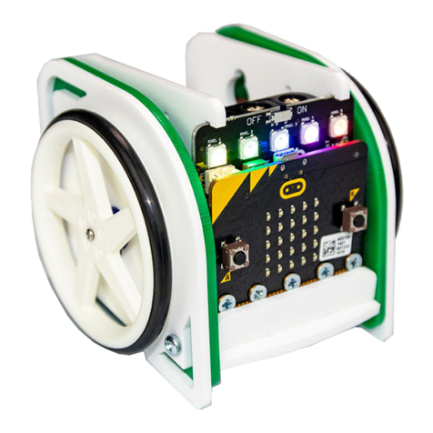
360 NANO BOT
THE COMPLETE ALL IN ONE
ROBOT

LINE FOLLOWER
FIVE LINE SENSORS FOR SCANNING
WHITE OR BLACK LINE
OBSTACLE AVOIDER
TWO OBSTACLE SENSORS CAN DETECT
OBSTACLES AND MEASURE DISTANCE
BLUETOOTH CONTROL
CONNECT A BLUETOOTH MODULE &
CONTROL IT FROM AN ANDROID

JUST ANOTHER
ARDUINO NANO
CONNECT THE USB CABLE &
START PROGRAMMING IT
FROM ARDUINO IDE
8×2 CHARACTER
LCD
WITH BACKLIGHT CONTROL OPTION
USING ONBOARD MICROCONTROLLER

EASY PLUGGABLE RECHARGEABLE BATTERY

INSPIRED BY 3PI ROBOT
We were impressed by the features and popularity of the “3pi robot” from
Pololu but disappointed at the same time due to its limitations and high price
tag.
So, we made our own robot, something way more user friendly with a bunch
of added features and options. And of course with an affordable price.

360 Nano Bot
Pololu 3PI
Microcontroller
Atmega 328
Atmega 328
Motor Controller
TB6612FNG
TB6612FNG
Motors
250 RPM high torque (more controllable)
700 RPM low torque
Programmer
Built-in
Not included, have to buy an AVR programmer
separately
USB to Serial
Built-in
Not included, have to buy separately
Arduino
compatibly
Arduino Nano built-in, supported by Arduino
IDE out of the box
Not supported out of the box, but Arduino software
can be modified to add support
Obstacle sensor
Built-in
Not available
Bluetooth
HC-05 connector, isolated
No Bluetooth module connector
Battery
2S Li-ion rechargeable battery, Included in
product package
AAA Alkaline batteries, Have to buy separately
Charger
Included in product package
Have to buy separately if needed
LCD
8X2 monochrome LCD with digitally
controllable backlight
8X2 monochrome LCD, no backlight
Battery voltage
indicator
Indicated by power LED
Measured by microcontroller. Requires writing
additional code to show battery voltage on LCD
Size (Diameter)
10 cm
9.42 (3π) cm
Price
See product page (including battery & charger)
USD 99.95 (BDT 8085 approximately)
COMPARISON

A CLOSER LOOK

Line Sensors: Five TCRT-5000
infrared line sensors for scanning
white or black line
Microcontroller: Atmega328
running on 16 MHz, flashed with
Arduino Nano bootloader
Motor Driver: TB6612FNG,
running on 7.1 –8.4 volts, controls
the speed and direction of rotation
of two geared DC motors
USB to Serial Converter:
FT232RL ic controls
programming and serial
communication of the
microcontroller
Ball casters: Two ball casters
provide smooth movement.
Having ball casters on both front
and rear side prevents stumbling
during both acceleration and
brake
Wheels: Wide wheels with
grooved tires provide better
grip. wheel diameter is 4 cm
Power LEDs: Two power LEDs
act as both power and battery
level indicator. They dims when
battery charge is low
USB: USB mini-B port, same as
Arduino Nano

ANOTHER CLOSER LOOK

User LEDs: Five user LEDs, controllable from the microcontroller. They share the same microcontroller
pins used for LCD. Not accessible while the shield is connected.
Shield Connectors: Two sets of shield connector for attaching the shield and thus controlling LCD,
obstacle sensors and optional Bluetooth module.
User pot: Connected to an ADC pin of the microcontroller via pot jumper.
User Buttons: Three user configurable buttons.
Alternate Power Input: In case you want to use a different battery instead of the one provided with
the package. Be careful about the voltage polarity if using these pins.
Reset Button: To reset the atmega328 microcontroller.
Buzzer: Just an audio output.
Motors: High torque 250 rpm motors.
Battery connector: For plugging in the 2S Li-ion battery provided with the package.
Power switch: On-off switch. It’s also a power selector switch for choosing power either from battery
or USB port. Slide towards USB port to select USB power and you’ll be able to test your program
while the battery is charging. It also switches off the robot if USB cable is not connected. Slide
towards battery connector to select battery power. You can run motors only on Battery power.
Power LED Toggle Switch: If you don’t like to keep the power LEDs always turned on or simply want
to save some battery juice.

ACCESSING USER LEDs
Connect 5 jumpers as shown by the RED
LINES in the picture below to connect the 5
user LEDs to internal Arduino Nano pins
11, 12, 13, 0 & 1 from left to right.
You cannot attach the shield while the 5
user LED jumpers are connected.
Putting a jumper indicated by the YELLOW
line in the picture below connects the user
pot to the microcontroller. The shield can be
attached without removing it.
JUMPER DIAGRAM
11
12
13
0
1

Obstacle Sensor Switch: Obstacle sensors draw a lot of
current draining the battery quickly. Switch them off
when not in use. Push towards → direction to turn on.
Obstacle Sensors: Two TCRT-5000 based obstacle
sensors can detect obstacle in front, left and right side up
to 10cm distance. User can also detect obstacle distance
using these.
Bluetooth Connector: For directly plugging in a HC-05
bluetooth module.
LCD:8×2 character LCD connected to a 74595 shift
register. The display as well as the backlight can be
controlled using only 3 pins of the microcontroller.
THE SHIELD
ADDS LCD, OBSTACLE
SENSORS AND
BLUETOOTH
CONNECTOR

CIRCUIT CONNECTIONS
360 Nano Bot has got an Arduino Nano built-in. Illustrating circuit connections using
Arduino Nano for easy understanding.

MOTOR CONTROL
LEFT MOTOR
Arduino Pin 9 & 10 Control
Direction
Arduino Pin 5 Controls Speed
RIGHT MOTOR
Arduino Pin 8 & 7 Control
Direction
Arduino Pin 6 Controls Speed
Now let’s rotate the motors at both forward and reverse directions, at various
speeds.
Internal Arduino pins 9 (in1) & pin 10 (in2) controls forward & reverse direction
of the left motor. Pin 5 (EnA) controls left motors speed.
Pin 8 (in3) & pin 7 (in4) control right motor direction. Pin 6 (EnB) controls right
motor speed.
Click HERE for example code.

READING LINE SENSORS
The five line sensors are connected to internal
Arduino Nano analog pins A7, A0, A1, A2 & A3 as
shown in the picture beside.
These sensors provide analog voltage output. When
the robot is placed on a surface, these sensors
output high voltage over white surface and low
voltage over black surface.
The difference of voltage output value on white &
black surface is quite high (about 3 volts).
Click HERE for example code. Upload the code, open
Serial monitor at 9600 baud rate and you’ll see
readings from the sensors.

Three button are connected in a voltage divider circuit as
shown in the picture beside. Thus pressing each button will
generate definite voltage at the Signal pin connected to
internal Arduino Nano ADC pin A6.
The LCD as well as its transistor controlled backlight is
connected to the output of a shift register IC. So, by using
only 3 pins of the internal Arduino Nano (digital pins 11, 12
& 13) connected to the shift register, the LCD along with
the backlight can be controlled.
Click HERE for example code. You’ll be able to see detection
of each button by the microcontroller on the LCD.
You must have “LiquidCrystal595” library added to your
Arduino IDE for using the LCD. Download it from HERE. If
you don’t know how to add a zip library, this video can
help. Use Arduino IDE version 1.6.5 or later.
BUTTONS AND LCD

BUZZER AND USER POTENTIOMETER
A buzzer connected to internal Arduino Nano pin 4 can be used to generate an audible signal from
the robot. A user pot (potentiometer) is connected to Arduino analog pin A4. The pot jumper is used
to connect the pot to Arduino Analog pin A4. By removing the jumper, you can connect pin A4 to any
of the 5 front LEDs using female-female jumper wire while the shield is attached and control the LED
by using pin A4 as a digital pin (pin 18).
Code for accessing the pot and the buzzer can be found HERE. It lets you control the buzzer by
rotating the pot.

OBSTACLE SENSORS
The obstacle sensors work by the same capacitor discharge principle as our other obstacle sensor.
Obstacles present at up to 10cm distance on right, left and front (large obstacle) side can be detected.
Distance of the obstacle within the range can also be measured.
Code for accessing the obstacle sensors can be found HERE. Presence of obstacle detected by both of
the two sensors as well as obstacle distance can be viewed on LCD display.
Obstacle sensors draw a lot of current from the battery and reduce run time. Slide the obstacle
sensor switch towards → direction (left) to turn on the obstacle sensors. Slide to the other
direction (right) to turn them off when not in use and save battery juice.

BLUETOOTH CONNECTOR
A connector for the popular HC-05 bluetooth module provides easy bluetooth add-on capability to the
robot. When attached, bluetooth TX gets connected to internal Arduino Nano pin 0 and Bluetooth RX
to Arduino pin1.
As the bluetooth data pins and Arduino programming pins (pin0 & pin1) are the same, consider
removing the bluetooth module while uploading program. Bluetooth can be used while USB is
connected.
Download the android app for making android controlled robot from HERE. Code for using bluetooth
can be found HERE. It shows the data sent over Bluetooth on robots LCD display. Also, you can move
the robot forward from your phone/tab using the app. Code for rest of the motions is left
for the user to write.
Table of contents


