RoboMaster University Series User manual


2© 2023 DJI All rights reserved.
Using this Manual
Prohibition Important notes Hints and tips Definitions and references
Change Log
The manual will take effect from the specified date after its release.
Date Version Release Notes Effective Date
July 11, 2023
1. Added requirements for whole robots
2. Added new rules relating to the mineral-grabbing
mechanism
3. Added new rules relating to the inspection of Sentry
Robots
4. Revised rules relating to the Dart System
5. Added new rules relating to visual markers
6. Revised installation requirements relating to the
UWB Module
7. Added new rules for the Power Management Module
and Super-capacitor Module
July 11, 2023
March 31, 2023 V1.2
1. Added new installation rules for robots' Light
Indicator Module.
2. Added new definition for robot chassis.
3. Added relevant specifications for cylinders and heat
source.
4. Added relevant specifications for Customer
Controllers.
5. Added relevant rules for robots' school badges.
6. Modified the relevant descriptions of the batteries.
7. Modified the descriptions of robots' visual feature.
March 31, 2023

©2023 DJI All rights reserved.3
Date Version Release Notes Effective Date
8. Modified the relevant requirements for propulsion
with compressed gas of the Launching Mechanism.
January 13, 2023 V1.1
1. Revised part of the General Technical Specifications,
mainly including the following:
Revised the relevant specifications in the “Gas
Source” chapter (S7)
Revised the relevant specifications in the
“Communication Equipment” (formerly “Wireless
Equipment”) chapter
Revised the relevant specifications for Launching
Mechanism
Added relevant definitions of third-party finished
modules
2. Revised part of the Robot Technical Specifications,
mainly including the following:
Added definitions of robot dimensions
Revised the relevant specifications for the Mineral-
Grabbing Mechanism and Referee System of
Engineer Robots
Revised the relevant specifications for the Referee
Systems and Existing Launching Mechanisms Hero
and Standard Robots
Revised the relevant specifications for the propulsion
mechanisms of Balancing Standard Robots
Added relevant specifications for the rigid ring on the
protective rod of Aerial Robots
Revised the relevant specifications for the Existing
Launching Mechanism, strength, and Referee System
of Sentry Robots
Revised the descriptions of the Radar computing
platform
January 13, 2023

4© 2023 DJI All rights reserved.
Date Version Release Notes Effective Date
3. Revised part of the Referee System Mounting
Specifications, mainly including the following:
Added relevant specifications for robot
transformation
Revised the installation requirements for Sentry
Armor Modules (S108)
4. Fixed known issues and improved some descriptions
October 26, 2022 V1.0 First Release October 26, 2022

©2023 DJI All rights reserved.5
TABLE OF CONTENTS
Using this Manual ..................................................................................................................................... 2
Change Log .............................................................................................................................................. 2
1. Foreword........................................................................................................................................ 11
2. Technical Specifications ................................................................................................................. 12
2.1 General Technical Specifications ............................................................................................... 12
2.1.1 Energy Source................................................................................................................... 12
2.1.2 Communication Equipment................................................................................................ 13
2.1.3 Optical Equipment............................................................................................................. 15
2.1.4 Visual Feature ................................................................................................................... 15
2.1.5 Armor Stickers .................................................................................................................. 16
2.1.6 Aesthetic Design ............................................................................................................... 16
2.1.7 Launching Mechanism....................................................................................................... 17
2.1.8 Custom Controller ............................................................................................................. 18
2.1.9 Miscellaneous ................................................................................................................... 20
2.2 Rules of Usage for Fully Assembled Robots and Open-Source Robots.......................................... 20
2.2.1 Complete Redesign............................................................................................................ 21
2.2.2 Partial Redesign ................................................................................................................ 22
2.2.3 Minimal Redesign ............................................................................................................. 23
2.3 Robot Technical Specifications.................................................................................................. 23
2.3.1 Hero Robot ....................................................................................................................... 23
2.3.2 Engineer Robot ................................................................................................................. 25
2.3.3 Standard Robot.................................................................................................................. 26
2.3.4 Aerial Robot ..................................................................................................................... 29
2.3.5 Sentry Robot ..................................................................................................................... 33
2.3.6 Dart System ...................................................................................................................... 34
2.3.7 Radar................................................................................................................................ 39
3. Referee System Mounting Specifications ........................................................................................ 42
3.1 Introduction.............................................................................................................................. 42
3.2 Configuration of Robot Referee System ..................................................................................... 43
3.3 Specifications for Mounting Main Controller Module.................................................................. 45
3.3.1 Installation Steps ............................................................................................................... 46
3.3.2 Installation Requirements................................................................................................... 47
3.4 Mounting Power Management Module....................................................................................... 48
3.4.1 Installation Steps ............................................................................................................... 49
3.4.2 Installation Requirements................................................................................................... 51
3.5 Mounting Light Indicator Module .............................................................................................. 54
3.5.1 Installation Steps ............................................................................................................... 55
3.5.2 Installation Requirements................................................................................................... 57
6© 2023 DJI All rights reserved.
3.6 Armor Module Mounting Specifications..................................................................................... 57
3.6.1 General............................................................................................................................. 59
3.6.2 Installation Steps ............................................................................................................... 62
3.6.3 Installation Requirements................................................................................................... 66
3.6.4 ID Number Configuration .................................................................................................. 68
3.7 Mounting Speed Monitor Module .............................................................................................. 69
3.7.1 Installation Steps ............................................................................................................... 70
3.7.2 Installation Requirements................................................................................................... 76
3.8 Mounting RFID Interaction Module ........................................................................................... 77
3.8.1 Installation Steps ............................................................................................................... 78
3.8.2 Installation Requirements................................................................................................... 79
3.9 Mounting VTM Transmitter ...................................................................................................... 80
3.9.1 Installation Steps ............................................................................................................... 81
3.9.2 Installation Requirements................................................................................................... 81
3.10 Mounting Video Transmitter Module (Receiver)......................................................................... 82
3.10.1 Installation Requirements................................................................................................... 82
3.11 Mounting Positioning System Module........................................................................................ 82
3.11.1 Installation Steps ............................................................................................................... 83
3.11.2 Installation Requirements................................................................................................... 84
3.12 Installation Specifications for 17mm Fluorescent Projectile Energy-Charging Devices................... 85
3.12.1 Installation Steps ............................................................................................................... 86
3.12.2 Installation Requirements................................................................................................... 86
3.12.3 Instructions and Requirements for Production of UV Light Panels ........................................ 87
3.13 Super-capacitor Management Module Installation Specifications ................................................. 88
3.13.1 Installation Steps ............................................................................................................... 88
3.13.2 Installation Requirements................................................................................................... 90
Appendix 1 Drawing of Adapter Block for Speed Monitor Module (17mm projectile)............................... 91
Appendix 2 Reference Drawings................................................................................................................ 92

©2023 DJI All rights reserved.7
Table Directory
Table 2-1 Summary of Control Methods ....................................................................................................... 13
Table 2-2 Summary of Remote Controllers ................................................................................................... 14
Table 2-3 Description of Custom Controller production parameters ................................................................ 18
Table 2-4 Hero production parameters .......................................................................................................... 23
Table 2-5 Hero Robot production parameters ................................................................................................ 25
Table 2-6 Standard production parameters..................................................................................................... 26
Table 2-7 Aerial Robot production parameters............................................................................................... 29
Table 2-8 Sentry production parameters ........................................................................................................ 33
Table 2-9 Dart production parameters ........................................................................................................... 35
Table 2-10 Dart Launcher production parameters........................................................................................... 35
Table 2-11 Radar Computing Platform production parameters ........................................................................ 39
Table 2-12 Radar Sensor parameters............................................................................................................. 40
Table 3-1 Referee System Component Modules............................................................................................. 42
Table 3-2 Configuration of Robot Referee System Modules ........................................................................... 43
Table 3-3 Descriptions of Power Management Module ports .......................................................................... 53

8© 2023 DJI All rights reserved.
Diagram Directory
Figure 2-1 A Balancing Standard Robot ........................................................................................................ 29
Figure 2-2 Effective Area of the External Navigation Lights........................................................................... 32
Figure 2-3 Dart Trigger Device .................................................................................................................... 37
Figure 2-4 Areas not allowed to be blocked on a Dart Trigger Device ............................................................. 38
Figure 2-5 Dart Trigger Device internal cavity .............................................................................................. 38
Figure 3-1 Main Controller Module.............................................................................................................. 46
Figure 3-2 Mounting Main Controller Module............................................................................................... 47
Figure 3-3 Main Controller Module Connection ............................................................................................ 47
Figure 3-4 Graph of Main Controller Module mounting position .................................................................... 48
Figure 3-5 Power Management Module ........................................................................................................ 49
Figure 3-6 Power Management Module Mounting Graph............................................................................... 50
Figure 3-7 Power Management Module Port ................................................................................................. 51
Figure 3-8 Power Management Module Connection ...................................................................................... 51
Figure 3-9 Light Indicator Module ............................................................................................................... 55
Figure 3-10 Mounting Light Indicator Module .............................................................................................. 56
Figure 3-11 Bottom of Light Indicator Module.............................................................................................. 56
Figure 3-12 Light Indicator Module Cable Connection .................................................................................. 56
Figure 3-13 Designated Armor Support Frame .............................................................................................. 57
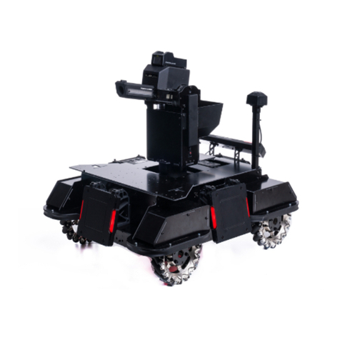
Figure 3-14 Small Armor Module Graph....................................................................................................... 58
Figure 3-15 Large Armor Module................................................................................................................. 58
Figure 3-16 Robot Coordinate System .......................................................................................................... 59
Figure 3-17 The X-axes of different robot chassis structures........................................................................... 60
Figure 3-18 Application of Force on Armor Module ...................................................................................... 61
Figure 3-19 Robot Protection ....................................................................................................................... 62
Figure 3–20 Reserved Holes on the Chassis .................................................................................................. 63
Figure 3-21 Mounting Armor Support Frame ................................................................................................ 63
Figure 3-22 Armor Module Mounting Diagram ............................................................................................. 64
Figure 3-23 Armor Module Cabling Diagram................................................................................................ 64
Figure 3-24 Reserved mounting holes on chassis........................................................................................... 65
Figure 3-25 Mounting Armor Support Frame ................................................................................................ 65
Figure 3-26 Armor Module Mounting Diagram ............................................................................................. 66
Figure 3-27 Ground Robot Armor Module ID Setting .................................................................................... 69
Figure 3-28 17mm Speed Monitor Module.................................................................................................... 70
Figure 29- 42mm Speed Monitor Module ..................................................................................................... 70

©2023 DJI All rights reserved.9
Figure 3-30 17mm barrel ............................................................................................................................. 71
Figure 3-31 Mounting Speed Monitor Module .............................................................................................. 72
Figure 3-32 17mm Adapter Block ................................................................................................................ 72
Figure 3-33 Securing method for 17mm Adapter Block.................................................................................. 73
Figure 3-34 Mounting 17mm short barrel...................................................................................................... 74
Figure 3-35 42mm Barrel ............................................................................................................................ 75
Figure 3-36 Speed Monitor Module Mounting Specification .......................................................................... 77
Figure 3-37 RFID Interaction Module........................................................................................................... 78
Figure 3-38 RFID Interaction Module Cable Connection ............................................................................... 78
Figure 3-39 Mounting RFID Interaction Module ........................................................................................... 79
Figure 3-40 VTM Transmitter ...................................................................................................................... 80
Figure 3-41 Mounting VTM Transmitter....................................................................................................... 81
Figure 3-42 VTM Transmitter Graph ............................................................................................................ 82
Figure 3-43 Positioning System Module ....................................................................................................... 83
Figure 3-44 Positioning System Module ....................................................................................................... 83
Figure 3-45 Positioning System Module Cable Connection ............................................................................ 83
Figure 3-46 Positioning System Module ....................................................................................................... 84
Figure 3-47 17mm Fluorescent Projectile Energy-Charging Device ................................................................ 85
Figure 3-48 Mounting UV Light Panel.......................................................................................................... 86
Figure 3-49 Capacitor Management Module Connection................................................................................ 89

10 © 2023 DJI All rights reserved.
Appendix Directory
Appendix Diagram 1 Hero Armor Sticker - No. 1 .......................................................................................... 92
Appendix Diagram 2 Engineer Armor Sticker - No. 2 .................................................................................... 92
Appendix Diagram 3 Standard Armor Sticker - No. 3 .................................................................................... 93
Appendix Diagram 4 Balancing Standard Robot Armor Sticker - No. 3........................................................... 93
Appendix Diagram 5 Standard Armor Sticker - No. 4 .................................................................................... 94
Appendix Diagram 6 Balancing Standard Robot Armor Sticker - No. 4........................................................... 94
Appendix Diagram 7 Standard Armor Sticker - No. 5 .................................................................................... 95
Appendix Diagram 8 Balancing Standard Robot Armor Sticker - No. 5........................................................... 95
Appendix Diagram 9 Sentry Armor Sticker................................................................................................... 96
Appendix Diagram 10 Outpost Armor Sticker ............................................................................................... 96
Appendix Diagram 11 Base Small Armor Sticker .......................................................................................... 97
Appendix Diagram 12 Base Large Armor Sticker .......................................................................................... 97

©2023 DJI All rights reserved.11
1. Foreword
Teams participating in RoboMaster are required to develop and build their robots. Participating robots are required
to meet all specifications described in this document, which will be the basis of the inspection. If any safety incident
has occurred due to a violation of rules, the RoboMaster Organizing Committee (“RMOC”) reserves the right to
hold the violating party legally responsible. Any dispute arising from this Specification Manual will be settled based
on interpretations provided by the Chief Referee or Head Inspector.
Users are advised to read the manuals for the various Referee System modules to learn about their respective
functions and how to install them. After installing the Referee System modules, refer to the Referee System User
Manual to understand its overall functions. The document can be downloaded at this link:
https://www.robomaster.com/zh-CN/products/components/referee?djifrom=nav

12 © 2023 DJI All rights reserved.
2. Technical Specifications
2.1 General Technical Specifications
2.1.1 Energy Source
The use of combustion engines, explosives, and hazardous chemicals is forbidden.
Participating teams are forbidden from using mains supply in the Competition Area (except for
Radars).
Use of hydraulic or other propulsion methods capable of causing pollution is forbidden.
For robots limited by their chassis power, the horizontal movements of their chassis can only be
propelled by electricity.
S1 Robots can be powered only by electricity and air pressure.
2.1.1.1 Power Supply
S2 Only batteries produced by DJI or other official manufacturers can be used on robots and Customer Controllers,
except only for Darts which may use lithium batteries produced by other official manufacturers.
S3 The total nominal energy of the Single Super-capacitor Modules of Standard, Hero and Sentry Robots must
not exceed 2000 J, and their actual measured energy must not exceed 2200 J. The nominal energy calculation
formula for a single capacitor module is E = 1
2
∗C∗U2(U refers to the withstand voltage value of the
capacitor and C refers to capacitance).
S4 Only Hero, Standard, and Sentry Robots can use the Super-capacitor Module. Each robot is allowed to use not
more than one Super-capacitor Module.
2.1.1.2 Gas Source
S5 The compressed gas pressure inside the gas cylinder (for storage) must not exceed 20 Mpa. The gas cylinder
(for storage) used should have a nominal pressure of no less than 30 MPa. A double-gauge regulator should be
mounted directly at the outlet of the gas cylinder (for storage). The working pressure must not exceed 0.8 Mpa.
S6 The working gas must be non-flammable, non-toxic and non-polluting, such as air, nitrogen, and carbon
dioxide.
S7 Any mechanism for using or storing gas (cylinders for storage, cylinders for proplusion, air spring, etc.) must
come with an approval certificate or nameplate stamp that is easy to inspect when required.

©2023 DJI All rights reserved.13
S8 If a gas cylinder (for storage) is still within its service life, it must be returned to the factory for maintenance
within the period specified by the user manual or product label, after which the proof of maintenance must be
submitted.
S9 The gas cylinder must have been issued an approval certificate by an officially recognized approving institution
in its country of manufacture.
S10 The gas cylinder (for storage) must be firmly and safely mounted on the robot, with at least two fixed points
that are more than 1/5 of its length apart or with one fixed surface that is more than 1/5 of its length. The gas
cylinder (for storage) and pipe must be protected to avoid any damage caused by tumbling over, collision,
rotation or faulty moving parts. The cylinder’s opening must not be exposed, so as to prevent it from being hit
and damaged by projectiles. To ensure safety, the cylinder’s opening must be kept horizontal or facing up.
S11 The gas cylinder (for storage) should be mounted in a way that the cylinder and the gas pipe never touch the
ground, regardless of how the robot spins around.
S12 No inflammables are allowed to be within 50 mm from the gas cylinder.
S13 All gas pipes and parts must be able to withstand the maximum working pressure of the system. It is
recommended for a safety relief valve to be installed on the low pressure gas circuits
2.1.2 Communication Equipment
The RMOC recommends that teams use the Video Transmitter Module Link (hereinafter referred
to as “VTM Link”) to control their robots.
The VTM Link refers to the link in the VTM used to transmit robot control-related data. It can
replace the DT7 and offer more superior stability.
For protocols related to the VTM Link, please refer to the Referee System Serial Port Protocol
Appendix.
S14 The control methods specified for this competition season are as shown in the table below.
Table 2-1 Summary of Control Methods
Data Link Information Transmitted
DT7 Remote Controller Mouse and keyboard commands, control stick movements
Other Remote Controllers Control stick movements
VTM Link Custom Controller, mouse and keyboard commands
Serial port of the Referee System Inter-robot communication, Dart launching command
S15 The remote controllers specified for this competition season are as shown in the table below. Only remote

14 © 2023 DJI All rights reserved.
controllers within the frequency band of 2.4G are permitted to be used, and only DT7 Remote Controllers may
be connected to the client. The RMOC only ensures the stability of the VTM Link.
Table 2-2 Summary of Remote Controllers
Name Image
DT7
FS-i6X
WFLY ET08
WFLY ET16S
S16 Each remote controller can only be linked to one receiver.
S17 Remote controllers cannot be modified.
S18 Robots are not allowed to carry wireless communication equipment other than the remote controller (RC) and
Referee System Module.

©2023 DJI All rights reserved.15
2.1.3 Optical Equipment
Teams are advised not to set up a laser sight when building a robot.
The use of custom UI is recommended, instead of a laser sight.
S19 The laser beam from the laser sight must be red and the optical power consumption of the laser beam must be
less than 35 mW. The projection angle of the laser sight must not exceed 5° (i.e. the diameter of the laser spot
enclosing circle perpendicularly projected by the laser sight on a vertical wall with a horizontal distance of one
meter must be less than 9 cm).
S20 Each Launching Mechanism and Dart Launcher can be equipped with a maximum of one laser sight. Engineers
can be mounted with not more than three laser sights. Apart from those needed to position the Launching
Mechanism, no additional laser sights may be used by other robots.
S21 Besides laser sights, Engineers can also be mounted with a white supplement light and a display screen not
larger than 7 inches. The light can only be used for enhancing visual recognition features when the robot is
acquiring a mobile component (a mineral or obstacle block). The display screen must not interfere with the
robot’s visual recognition features. Other robots must not be equipped with other obvious visible light emitting
equipment.
S22 The optical equipment used by a robot must not cause any physical harm to any person.
S23 All infrared light sources must conform to the Class I requirements.
2.1.4 Visual Feature
On both sides of the Referee System Armor Module are clear lighting effects to enable robots to develop automatic
recognition and sighting algorithms. The environment in and around the Competition Area is relatively complex.
The RMOC cannot guarantee that the computer visual features of the Battlefield will not cause visual interference.
The computer vision algorithm should adapt to the changes of the lighting of the venue and other possible
interferences around the venue.
The following specifications must be followed when designing a robot’s computer visual features:
S24 Armor Modules cannot be blocked.
S25 Visual feature imitation is not allowed.
S26 One team must not, through any means, interfere with the detection of its robot visual features by the other
team’s robot.

16 © 2023 DJI All rights reserved.
Robot visual features: Light indicators on both sides of the Armor Module, and armor stickers.
2.1.5 Armor Stickers
During Pre-Match Inspections and matches, RMOC staff will provide armor stickers to robots based on their robot
numberings. For images of the stickers, please refer to “Appendix 2: Reference Drawings”. For robot numberings,
please refer to the “Robot Line-up” chapter in the RoboMaster 2023 University Championship Rules Manual.
The following specifications must be followed when attaching armor stickers on robots:
S27 The armor stickers and serial number of a robot must match one another according to the numbering rules. The
number and symbol must be placed in the correct direction, with no visible air pockets and no damage to the
stickers. One Armor Module may be attached with not more than one armor sticker.
S28 The armor stickers provided by the RMOC can only be attached on the Armor Module. Except for the armor
stickers provided by the RMOC, no other stickers that resemble the armor stickers in their patterns may be
attached on a robot’s Armor Module or its other external structures.
2.1.6 Aesthetic Design
To ensure the protective shells of robots do not affect the shootout battles in the Competition Area and the match-
viewing experience, the following specifications must be followed when designing and creating a robot’s exterior:
Basic Requirements:
S29 The cables of robots are neat and not exposed. Exposure that is unavoidable requires cables protection using
materials such as drag chains and cable managers.
S30 Do not use materials that will have an obvious impact on the aesthetics of the robot, such as washbasins, plastic
bottles, corrugated paper, bed sheets, white foam boards, bubble wrap, etc.
S31 Fishing net cannot be used as an aesthetic material, but can be used in the protective guard of an Aerial Robot.
S32 Do not design or use sharp structures to avoid causing damage to the battlefield or injury to personnel.
Gloss:
S33 The exterior gloss of robots must not exceed 30Gs,
An exception is made for optical equipment, such as camera lenses and other equipment that cannot be
made non-
glossy. However, they must be kept more than 100 mm away from the edge of the Armor
Module side indicators.
Paint Color:

©2023 DJI All rights reserved.17
All the robots of a team should preferably have a consistent aesthetic style.
S34 The Red Team’s robots may use a color from the red spectrum for their protective shell, while the Blue Team
may use any color from the blue spectrum. However, neither team should use the opposing team's color.
S35 A robot must display two school badges or team badges, each facing a different side. The size of a single school
badge or team badge must not be larger than 100mm*100mm. The school badges or team badges must be
displayed prominently on a robot, and their distance with the Armor Module side indicators must be more than
30 mm. If the exterior of a robot does not meet specifications, an Inspector may require the position or size of
a school badge or team badge to be altered.
S36 The inkjet or stickers of the school and team badges must not affect the robot’s visual features, and cannot be
illuminated.
S37 Inverse colors can be applied on a school badge or team badge, or its original colors can be retained.
Mounting of Protective Shells:
It is recommended that teams use tough materials that are not easily damaged for the protective shell
and conduct reliability tests, to avoid any violation of rules caused by breakage of the protective shell
from battles in the Competition Area.
Aesthetic Requirements:
S38 Inverse colors can be applied for advertising spaces, or their original colors can be retained.
S39 The advertising spaces should be displayed on the left and right sides of the robot, and their distance with the
Armor Module side indicators must not be less than 30 mm.
S40 The inkjet or stickers of the advertising spaces must not affect the robot's visual features, and cannot be
illuminated.
S41 The size of a single robot advertising space shall not be more than 100mm*100mm. Each robot can be set with
up to two advertising spaces for the display of sponsor information. If the exterior of a robot does not meet
specifications, an Inspector may require the position or size of an advertising space to be altered.
2.1.7 Launching Mechanism
Launching Mechanism: A mechanism that is able to launch a projectile from a robot along a fixed
trajectory to cause damage to another robot (it is not considered a Launching Mechanism if it cannot be
powered up).
S42 Robots using compressed gas as the propellant for projectiles must not have an acceleration length exceeding

18 © 2023 DJI All rights reserved.
200 mm (the acceleration must be completed before the projectile enters the Speed Monitor Module).
S43 Except for Aerial Robots, the Launching Mechanisms of robots must be able to stably launch 10 rounds of
17mm projectiles or five rounds of 42mm projectiles.
S44 Each Launching Mechanism must be installed with a Speed Monitor Module in accordance with the rules.
17mm Launching Mechanism must be mounted with a 17mm Fluorescent Projectile Energy-Charging Device
according to specifications.
Any robot mounted with an Optional 17mm Launching Mechanism will gain 0.2 kg for its weight in the
Referee System.
2.1.8 Custom Controller
The Custom Controller is a set of multi-purpose controllers made by the participating team and is used to control
and monitor robot movements and status.
The Custom Controller includes but is not limited to VR goggles and their supporting control
equipment, the joystick, self-built wired controller, and other self-built control modules.
If the joystick is mapped onto the mouse, the joystick and Remote Controller combo shall be deemed
as one set of control equipment and not part of the Custom Controller.
L*W*H:Size, L*W*H
Table 2-3 Description of Custom Controller production parameters
Item Limit Notes
Target
Each robot may only be equipped
with one Custom Controller.
Custom Controllers are not allowed to be
used on Sentry Robots.
Maximum Power Supply
Capacity (Wh)
265 -
Maximum Power Supply
Voltage
(
V
)
30 -
Maximum Size (mm
,
L*W*H)
350*350*350
Excluding the size of wearable
devices such as video glasses (if any)
Excluding the size of data or power
cables of any equipment
Maximum Weight (kg) 10 Including the battery weight

©2023 DJI All rights reserved.19
Item Limit Notes
Data Transmission Serial Port Module -
Video Transmission Standard HDMI Type A Plug
The recommended resolution is
1920*1080. Otherwise compression or
distortion issues may occur.
Serial Data Transmission Able to send and receive The serial port standard is RS232.
Protocol Refer to the “Appendix to the Referee
System Serial Port Protocol”
-
Mounting Requirements:
S45 It is recommended that a non-slip pad is placed under the Custom Controller.
S46 Do not put any sticky or sharp items such as double-sided tape and screws in direct contact with the desk in
the operator room.
S47 Keep the cables of the Custom Controller neatly stored in the device without being exposed.
S48 The interface between the Custom Controller and the computer in the operation room should strictly comply
with the requirements specified in “Table 2-3 Description of Custom Controller production parameters”.
Unauthorized connection is strictly forbidden.
How to Use:
S49 Before you start to use the Custom Controller, you should test whether it functions properly by placing it on
the computer desk corresponding to the robot in the Operator Room and connect it to the data interface
available in the room.
S50 The Custom Controller must not be equipped with any wireless transmitter or receiver.
S51 The operator room is equipped with a standard HDMI Type A receptacle, which can be used to connect to the
display devices such as video glasses. The operator can display the client images on the video glasses by using
the screen mirroring function of the computer.
S52 An RS232 plug is provided in the Operator Room, for connecting Custom Controller signals. The Operator
can connect them on their own.
For self-
produced video glasses, the power supply must be provided by the Customer Controller. No
battery is allowed
to be mounted in the glasses (excluding commercial video glasses which come
with batteries).

20 © 2023 DJI All rights reserved.
For self-made controllers, only batteries produced by DJI or other official manufacturers can be used.
Use of mains electricity (220V) is strictly forbidden.
2.1.9 Miscellaneous
S53 No materials that are fragile, easy to fall off, and difficult to clean may be used in the production of robots,
such as feathers and cotton. No glue or adhesive materials may be used to attach robots to the battlefield or
battlefield components.
S54 Robots are not allowed to grab the Referee System Module of any robot.
2.2 Rules of Usage for Fully Assembled Robots and Open-
Source Robots
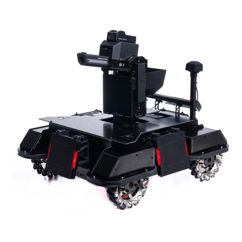
Only teams that did not qualify for the offline competitions of the RoboMaster 2022 University Series
(except for the RoboMaster 2022 University AI Challenge) are allowed to deploy a maximum of one
non-modified RoboMaster Robot Self-
Assembled Version Type A or one RoboMaster AI Robot
2020 Standard Version whose modification meets the new design criteria.
When building their robots, the remaining teams must not modify the abovementioned robots into a
newly designed robot or directly use their frame, material or other important components during the
production process, and are only allowed to use the motor coupling, Launching Mechanism, Loading
Mechanism, or other such parts of the abovementioned robots.
When building their robots, participating teams are forbidden from using third-
party assembly
modules, except for the flight system of Aerial Robots (including the frame, propulsion system, flight
control, and perception system).
Third parties: Entities other than the RMOC and participating teams.
Assembly modules: Special function components formed by several basic function
compone
nts, used for assembling a system with full functionality, such as robotic arms,
chassis, Super-capacitor
control panels and their supporting codes, gimbals, Darts,
suspension wheels, loading mechanisms, and Launching Mechanisms.
For the RoboMaster University Series, the RMOC have defined the ownership of intellectual property over the
participating robots. Only team members involved in the design and production of the robots and the universities or
colleges they represent shall own the intellectual property rights related to the robots’ design and form. Only the
Table of contents
Other RoboMaster Robotics manuals

RoboMaster
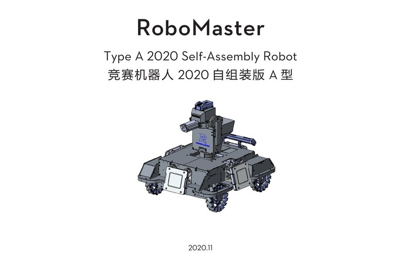
RoboMaster Type A 2020 User manual

RoboMaster
RoboMaster Referee System 2020 User manual

RoboMaster
RoboMaster AI Robot 2020 Standard Version User manual

RoboMaster
RoboMaster Youth Tournament Base 01 User manual

RoboMaster
RoboMaster CM01 User manual

RoboMaster
RoboMaster Standard A 2020 User manual