Tecnar Rotoweld 3.0 User manual

User
manual
Automated
welding
work
cell
for
pipe
spool
prefabrication

NOTICES
© 2017 Tecnar Automation Ltd.
No part of this manual may be reproduced in any form or by any means (including electronic storage and
retrieval or translation into a foreign language) without prior agreement and written consent from Tecnar
Automation Ltd.
MANUAL PART
40101-0020-00
This is version 1.2, released in July 2017
The material contained in this document is provided “as is” and is subject to change without notice in
future versions or revisions.
OVERVIEW:
• Table of content at the beginning of the document
• Table of figures at the beginning of the document
Orientation:
a Table of contents at the front of the manual
b Index at the rear of the manual
This manual contains the following sections:
c “Safety summary”
d “Introduction”
e “General description”
f “Operation of the workstation”
g “Editable parameters”
h “Contact us”
!
!
!
!

This document contains information considered proprietary and confidential to Tecnar Automation Ltd
40101-00020-00– Rev 1.2
Revision date: 2017-07-31
Page 3 of 48
!
TABLE OF CONTENT
1!SAFETY SUMMARY ....................................................................................................................................... 6!
2!INTRODUCTION ............................................................................................................................................. 9!
3!GENERAL DESCRIPTION ............................................................................................................................ 10!
4!OPERATION OF THE WORKSTATION ....................................................................................................... 12!
4.1!PREPARATION OF THE WELD ................................................................................................................. 12!
4.2!REMOTE PENDANT ............................................................................................................................... 13!
5!EDITABLE PARAMETERS ........................................................................................................................... 22!
5.1!ACCESS TO EDITING MODE .................................................................................................................... 28!
5.2!WELDER SECTION EDITING .................................................................................................................... 29!
5.3!PROCEDURES SECTION EDITING ............................................................................................................ 32!
5.4!PIPE SIZE EDITING ................................................................................................................................ 35!
5.5!ROOT PROCESS EDITING ....................................................................................................................... 36!
5.6!FILL PROCESS EDITING ......................................................................................................................... 42!
6!CONTACT US ............................................................................................................................................... 48!
6.1!SERVICE & SUPPORT ........................................................................................................................... 48!

This document contains information considered proprietary and confidential to Tecnar Automation Ltd
40101-00020-00– Rev 1.2
Revision date: 2017-07-31
Page 4 of 48
!
TABLE OF FIGURES
FIGURE 1 ROTOWELD 3.0 WORKSTATION ................................................................................................ 10!
FIGURE 2 REMOTE PENDANT OF THE ROTOWELD ................................................................................. 13!
FIGURE 3 POWER SWITCH (KEY) OF THE MACHINE ................................................................................ 13!
FIGURE 4 THE KEY THAT ENABLES OR DISABLES THE WELDING PARAMETERS ADJUSTMENT ...... 13!
FIGURE 5 THE SWITCH ................................................................................................................................. 14!
FIGURE 6 USB PORT ..................................................................................................................................... 14!
FIGURE 7 REMOTE PENDANT ..................................................................................................................... 16!
FIGURE 8 MAIN POWER SWITCH ................................................................................................................ 17!
FIGURE 9 ON/OFF SWITCH .......................................................................................................................... 18!
FIGURE 10 CALIBRATION SCREEN WILL DISPLAY ................................................................................... 19!
FIGURE 11 TORCH UP .................................................................................................................................. 19!
FIGURE 12 CALIBRATION IS COMPLETED ................................................................................................. 20!
FIGURE 13 MAIN SCREEN ............................................................................................................................ 21!
FIGURE 14 WELDER...................................................................................................................................... 22!
FIGURE 15 WELDER...................................................................................................................................... 23!
FIGURE 16 SELECT ....................................................................................................................................... 24!
FIGURE 17 SELECT, COPY, DELETE AND EDIT ......................................................................................... 25!
FIGURE 18 SELECT, COPY, DELETE AND EDIT ......................................................................................... 26!
FIGURE 19 WELDING LINE ........................................................................................................................... 27!
FIGURE 20 WELDING SCREEN .................................................................................................................... 28!
FIGURE 21 WELDER NAME SECTION ......................................................................................................... 29!
FIGURE 22 POPUP MENU ............................................................................................................................. 29!
FIGURE 23 ADD WELDER ............................................................................................................................. 30!
FIGURE 24 NEW WELDER NAME ................................................................................................................. 30!
FIGURE 25 DELETE WELDER ...................................................................................................................... 31!
FIGURE 26 PROCEDURE SECTION ............................................................................................................. 32!
FIGURE 27 POPUP WINDOW DISPLAYED .................................................................................................. 32!
FIGURE 28 COPY PROCEDURE ................................................................................................................... 33!
FIGURE 29 DELETE PROCEDURE ............................................................................................................... 34!
FIGURE 30 PIPE SIZE SECTION ................................................................................................................... 35!
FIGURE 31 ROOT PROCESS ........................................................................................................................ 36!
FIGURE 32 ROOT PROCESS SECTION ....................................................................................................... 36!
FIGURE 33 ROOT PROCESS PARAMETERS .............................................................................................. 36!
FIGURE 34 TORCH ANGLE PARAMETERS ................................................................................................. 37!
FIGURE 35 TORCH ANGLE ........................................................................................................................... 37!
FIGURE 36 DURATION PARAMETERS ........................................................................................................ 38!
FIGURE 37 EXIT DURATION PARAMETERS ............................................................................................... 38!
FIGURE 38 POWER SETTING PARAMETERS ............................................................................................. 38!
FIGURE 39 POWER SETTING ....................................................................................................................... 38!
FIGURE 40 WIRE SPEED PARAMETERS..................................................................................................... 39!
FIGURE 41 WIRE SPEED .............................................................................................................................. 39!
FIGURE 42 TRAVEL SPEED PARAMETERS ................................................................................................ 39!
FIGURE 43 TRAVEL SPEED .......................................................................................................................... 39!
FIGURE 44 DURATION PARAMETERS ........................................................................................................ 40!
FIGURE 45 DURATION .................................................................................................................................. 40!
FIGURE 46 ENABLE ....................................................................................................................................... 40!
FIGURE 47 DISABLE ...................................................................................................................................... 40!
FIGURE 48 TRAVEL SPEED MIN & MAX ...................................................................................................... 41!

This document contains information considered proprietary and confidential to Tecnar Automation Ltd
40101-00020-00– Rev 1.2
Revision date: 2017-07-31
Page 5 of 48
!
FIGURE 49 TRAVEL SPEED MIN & MAX ...................................................................................................... 41!
FIGURE 50 FILL PROCESS ........................................................................................................................... 42!
FIGURE 51 FILL PROCESS SECTION .......................................................................................................... 42!
FIGURE 52 SELECT THE DESIRED FILL PROCESS ................................................................................... 42!
FIGURE 53 TORCH ANGLE PARAMETERS ................................................................................................. 43!
FIGURE 54 TORCH ANGLE ........................................................................................................................... 43!
FIGURE 55 DURATION .................................................................................................................................. 43!
FIGURE 56 DURATION .................................................................................................................................. 43!
FIGURE 57 POWER SETTING ....................................................................................................................... 44!
FIGURE 58 POWER SETTING ....................................................................................................................... 44!
FIGURE 59 WIRE SPEED .............................................................................................................................. 44!
FIGURE 60 WIRE SPEED .............................................................................................................................. 44!
FIGURE 61 TRAVEL SPEED .......................................................................................................................... 45!
FIGURE 62 TRAVEL SPEED .......................................................................................................................... 45!
FIGURE 63 PRE FLOW AND POST FLOW- DURATION .............................................................................. 46!
FIGURE 64 PRE FLOW AND POST FLOW-DURATION ............................................................................... 46!
FIGURE 65 ENABLE ....................................................................................................................................... 46!
FIGURE 66 DISABLE ...................................................................................................................................... 46!
FIGURE 67 MISCELLANEOUS-TRAVEL SPEDD MIN & MAX ...................................................................... 47!
FIGURE 68 TRAVAEL SPEES MIN $ MAX .................................................................................................... 47!

This document contains information considered proprietary and confidential to Tecnar Automation Ltd
40101-00020-00– Rev 1.2
Revision date: 2017-07-31
Page 6 of 48
!
!
1 SAFETY SUMMARY
Always use a shield with the proper filter and cover plates to protect your
eyes from sparks as well as the welding arc radiation when observing open
arc welding. Head shield and filter lens should comply with ANSI Z87. I
standards.
Use suitable clothing made from durable flame-resistant material to protect
your skin and that of your helpers from the welding arc radiation.
Protect other nearby personnel with suitable, non-flammable screening
and/or warn them not to watch the arc nor expose themselves to the arc
radiation or to hot spatter or metal.
Welding may produce hazardous fumes and gases. Avoid breathing those
fumes and gases. When welding, keep your head out of the fume. Use
enough ventilation and/or exhaust in the arc zone to keep fumes and gases
away from the breathing zone. When welding with electrodes that require
special ventilation such as stainless or hard facing (see instructions on
container or MSDS) or on lead or cadmium plated steel and other metals or
coatings which produce highly toxic fumes, keep exposure as low as possible
and below Threshold Limit Values (TLV) using local exhaust or mechanical
ventilation. In confined spaces or under some circumstances outdoors, a
respirator may be required. Additional precautions are also required when
welding on galvanized steel.
Do not weld in locations near chlorinated hydrocarbon vapors coming from
degreasing, cleaning or spraying operations. The heat and radiation from the
arc can react with solvent vapors to form phosgene, a highly toxic gas, and
other irritating products.
Shielding gases used for arc welding can displace air and cause injury or
death. Always use enough ventilation, especially in confined areas, to ensure
breathing air is safe.
Read and understand the manufacturer’s instructions for this equipment and
the consumables to be used, including the material safety data sheet (MSDS)
and follow your employer’s safety practices. MSDS forms are available from
your welding distributor or from the manufacturer.
Remove any fire hazard from the welding area. If this is not possible, cover
them to prevent the welding sparks from starting a fire. Remember that
welding sparks and hot materials from welding can easily go through small
cracks and openings in adjacent areas. Avoid welding near hydraulic lines.
Always have a fire extinguisher readily available.
When compressed gases are to be used at the job site, special precautions

This document contains information considered proprietary and confidential to Tecnar Automation Ltd
40101-00020-00– Rev 1.2
Revision date: 2017-07-31
Page 7 of 48
!
!
should be taken to prevent hazardous situations. Refer to “Safety in Welding
and Cutting” (ANSI Standard Z49.1) and the operating information for the
equipment being used.
When not welding, make certain no part of the electrode circuit is touching
the work or ground. Accidental contact can cause overheating and create a
fire hazard.
Do not heat, cut or weld tanks, drums or containers until the proper steps
have been taken to ensure that such procedures will not cause flammable or
toxic vapors from substances inside. They can cause an explosion even
though they have been “cleaned”. For information, purchase “Recommended
Safe Practices for the Preparation for Welding and Cutting of Containers and
Piping That Have Held Hazardous Substances”, AWS F4.1 from the
American Welding Society (see address above).
Vent hollow castings or containers before heating, cutting or welding, as they
may explode.
Sparks and spatter are thrown from the welding arc. Wear oil free protective
garments such as leather gloves, heavy shirt, cuff less trousers, high shoes
and a cap over your hair. Wear earplugs when welding out of position or in
confined places. Always wear safety glasses with side shields when in a
welding area.
Connect the work cable to the work as close to the welding area as practical.
Work cables connected to the building framework or other locations away
from the welding area increase the possibility of the welding current passing
through lifting chains, crane cables or other alternate circuits. This can create
fire hazards or overheat lifting chains or cables until they fail.
Use only compressed gas cylinders containing the correct shielding gas for
the process used and properly operating regulators designed for the gas and
pressure used. All hoses, fittings, etc. should be suitable for the application
and maintained in good condition.
Always keep cylinders in an upright position securely chained to an
undercarriage or fixed support.
Cylinders should be located:
Away from areas where they may be struck or subject to physical damage.
A safe distance away from arc welding or cutting operations and any other
source of heat, sparks, or flame.
Never allow the electrode, electrode holder or any other electrically “hot”
parts to touch a cylinder.
Keep your head and face away from the cylinder valve outlet when opening

This document contains information considered proprietary and confidential to Tecnar Automation Ltd
40101-00020-00– Rev 1.2
Revision date: 2017-07-31
Page 8 of 48
!
!
the cylinder valve.
Valve protection caps should always be in place and hand tight except when
the cylinder is in use or connected for use.
Read and follow the instructions on compressed gas cylinders, associated
equipment, and CGA publication P-l, “Precautions for Safe Handling of
Compressed Gases in Cylinders,” available from the Compressed Gas
Association 1235 Jefferson Davis Highway, Arlington, VA 22202.
Turn off input power using the disconnect switch at the fuse box before
working on the equipment.
Install equipment in accordance with the U.S. National Electrical Code, all
local codes and the manufacturer’s recommendations.
Equipment must be properly grounded in accordance with the U.S. National
Electrical Code and the manufacturer’s recommendations.
NOTE: PRIOR TO USING THE ROTOWELD, THE INTERFACE
MANUAL/PENDANT CONSOLE SHOULD HAVE BEEN READ

This document contains information considered proprietary and confidential to Tecnar Automation Ltd
40101-00020-00– Rev 1.2
Revision date: 2017-07-31
Page 9 of 48
!
!
2 INTRODUCTION
Rotoweld 3.0 is a fully automated pipe-on-positioner welding system that
performs full penetration root and filler passes in an open bevelled butt joint.
It is specifically designed for industrial pipe prefabrication, small pressure
vessel manufacturing or other similar applications. Rotoweld produces high
quality welds three to four times faster than manual SMAW.
Rotoweld is based on a patented1 method to measure and control in real
time the penetration of the root pass in open butt joints. Developed by the
National Research Council of Canada, the method uses machine vision and
adaptive feedback to insure full penetration of the root and therefore a defect
free weld. Like a welder's eyes and hands, the system digitizes the full image
of the weld pool as picked up by a solid-state camera, analyses its shape and
reacts in real time on welding parameters, constantly adapting to varying
conditions such as changes in gap, root face or temperature. The system
operating range more than covers the tolerances typical of the average pipe
prefabrication shop.
The present document is divided into three main sections. The first section
offers a general description of the complete Rotoweld work cell. Part two of
the document details all operational aspects of the system. Finally, part three
contains technical specifications and other useful information
!
!!!!!!!!!!!!!!!!!!!!!!!!!!!!!!!!!!!!!!!!!!!!!!!!!!!!!!!!!!!!!
1 Nadeau, F., Fafard, P., Patenaude, G., and Tremblay, J. "Method and Apparatus for
Controlling Root Pass Weld Penetration in Open Butt Joints". US Patent #4,733,051, Mar. 22,
1988.

This document contains information considered proprietary and confidential to Tecnar Automation Ltd
40101-00020-00– Rev 1.2
Revision date: 2017-07-31
Page 10 of 48
!
3 GENERAL DESCRIPTION
!
FIGURE 1 ROTOWELD 3.0 WORKSTATION
The ROTOWELD 3.0 WORKSTATION is illustrated in figure 1 page 10. The
two major components are a positioner and a welding carriage, linked by a
flexible cable conduit. The carriage moves on rails parallel to the positioner's
axis allowing several welds along a single pipe spool to be performed in
sequence. The spool is supported by a set of idler rolls also guided by rails to
keep them aligned with the positioner's axis.
In the case of a Twin Workstation, there is an additional positioner mounted
on the same rail system therefore providing two independent workstations
sharing the same welding carriage. This allows off-line loading/unloading of
spools in the alternate work bay without interruption of the welding process,
thus maximizing arc-time.
The welding carriage consists of a base and a column on which a control
pendant, a monitor with the computer in the back, a torch manipulator with
oscillator and welding torches support (GMAW or SAW depending on the
model). The camera is incorporated just below the oscillator. In the base is
located the cooling water circulator. For SAW welding, a pressure flux system
(SAW fill model) is added at the back of the base carriage. The column
houses various controls, electronics, the wire feeder(s), the gas valves, the
flow meters, and the wirer spool(s).
The main positioners consist of a self-centering chuck and a face plate

This document contains information considered proprietary and confidential to Tecnar Automation Ltd
40101-00020-00– Rev 1.2
Revision date: 2017-07-31
Page 11 of 48
!
mounted on a horizontal axis, a drive gear, a gearbox, and a servo-motor.
The main positioner also houses the electronic motor drive, the welding
power sources and the power inlet of the machine.
The system consists of a choice of different configurations base track system
on which a turn table(s), idler rolls and the welding carriage are installed.
The root pass head is positioned and performs the root pass using the
system’s vision feedback algorithm with the Lincoln STT power source, and
the fill passes (either spray-MIG or SAW) use the Lincoln CV400i or
FLEXTEC 650 2. For the fill passes, the welding head is put in position and
perform the fill passes using the spray transfer / flux core or the submerged
arc welding process*. During welding a helper can load and prepare the next
spool to be welded by the operator to optimise arc on time.
!!!!!!!!!!!!!!!!!!!!!!!!!!!!!!!!!!!!!!!!!!!!!!!!!!!!!!!!!!!!!
2 Depending on the workstation configuration/options

This document contains information considered proprietary and confidential to Tecnar Automation Ltd
40101-00020-00– Rev 1.2
Revision date: 2017-07-31
Page 12 of 48
!
4 OPERATION OF THE WORKSTATION
The following is a step-by-step description of the operation of the Rotoweld
3.0
4.1 PREPARATION OF THE WELD
A standard beveled butt weld preparation should be used with the Rotoweld.
Machined or flamed-cut bevels between 30° and 37.5° are acceptable3. Once
a bevel angle is chosen, it should be kept the same for all preparations so to
avoid constant readjustment of the welding parameters.
Table 1 shows the ideal root face width and root gap as a function of pipe
size and thickness.
PIPE GAUGE AND
DIAMETER!
ROOT FACE
WIDTH!
ROOT GAP
2" to 8" std, 2" to 6"
HW (50 to 200 mm std,
50 to 100 mm HW)
3/32” to 1/8"
(2-3 mm)
1/8” to 5/32" (3 to 4 mm)
10" to 24" std, 8" to 24"
HW (250 to 600 mm std,
150 to 600 mm
3/32” to 1/8"
(2-3 mm)
5/32” to 1/4" (4 to 6 mm)
!
Misalignment (high-low) should not exceed half the root gap length.
Full penetration tacks must be performed using either GMAW or GTAW to
hold the two sections together. The tacks must be grinded over their entire
length (20 to 25 mm, 3/4” to 1”) and feathered at their ends to adequately
blend-in with the root pass. Proper tacking and tack grinding is critical, as any
defect in the tack will most likely remain in the finished weld.
Warning: If, for any reason, the operator interrupts the root pass before it is
finished, it is important to grind back 1/2" (15 mm) and feather the end of the
bead before restarting.
!!!!!!!!!!!!!!!!!!!!!!!!!!!!!!!!!!!!!!!!!!!!!!!!!!!!!!!!!!!!!
3 Standard Tecnar procedures are designed for 37.5° bevels.
This document contains information considered proprietary and confidential to Tecnar Automation Ltd
40101-00020-00– Rev 1.2
Revision date: 2017-07-31
Page 13 of 48
!
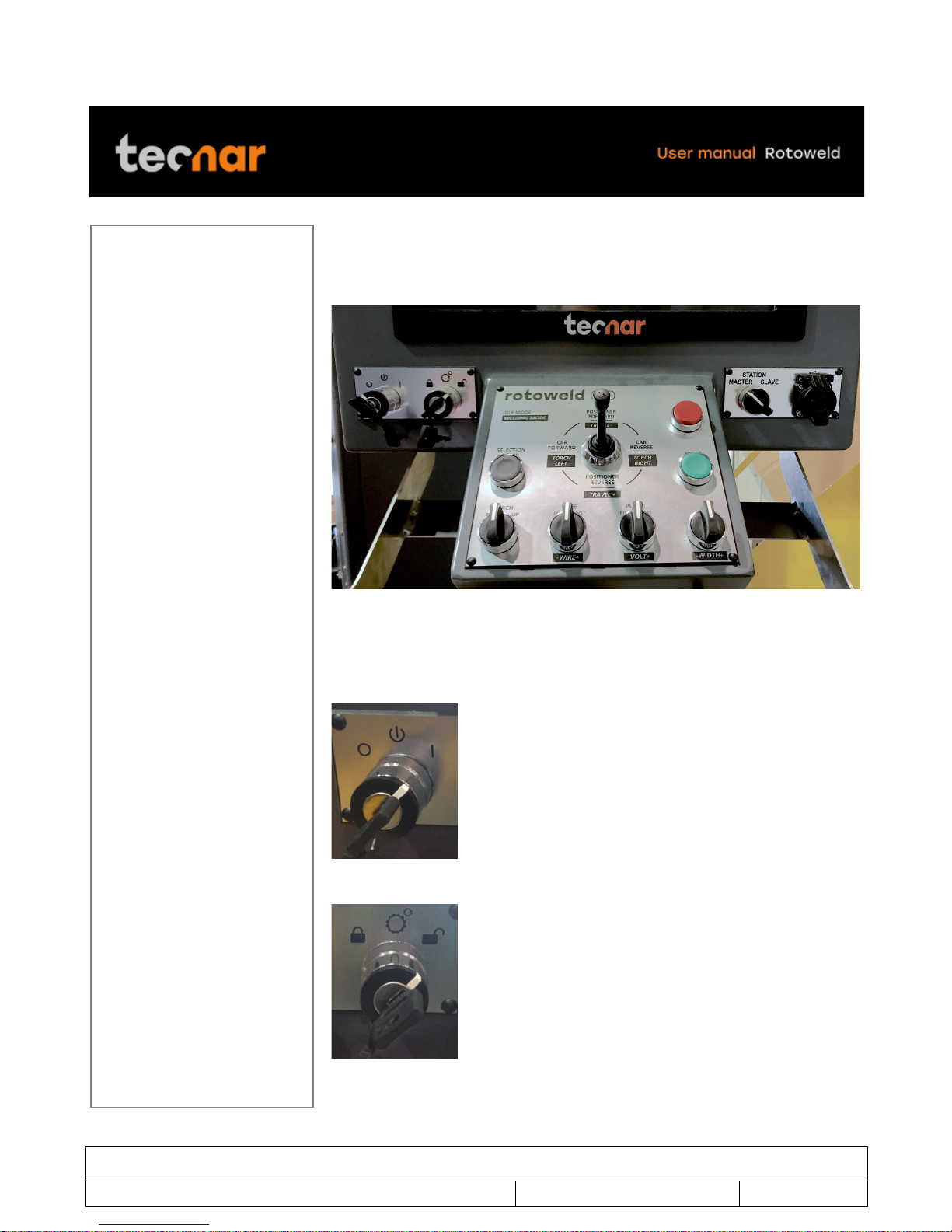
4.2 REMOTE PENDANT
Below is the typical remote pendant of the Rotoweld (figure 2) and its
controls.
FIGURE 2 REMOTE PENDANT OF THE ROTOWELD
On the left-hand side of the pendant, you will find both the power switch (key)
of the machine (Figure 3) and the key that enables or disables the welding
parameters adjustment (Figure 4).
FIGURE 3 POWER SWITCH (KEY) OF THE MACHINE
FIGURE 4 THE KEY THAT ENABLES OR DISABLES THE WELDING PARAMETERS
ADJUSTMENT
This document contains information considered proprietary and confidential to Tecnar Automation Ltd
40101-00020-00– Rev 1.2
Revision date: 2017-07-31
Page 14 of 48
!
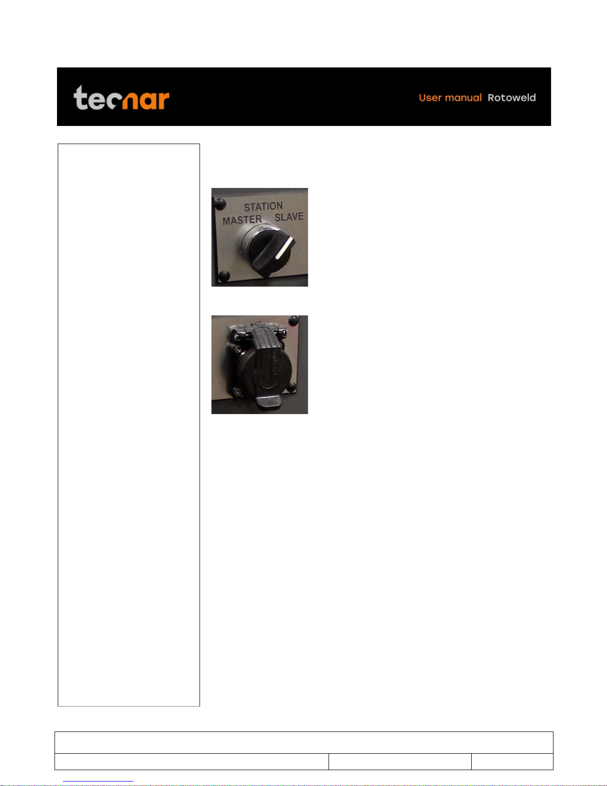
On the right-hand side of the pendant, you will find a switch (Figure 5) that
allows you to toggle between the master or the slave station. Just underneath
(Figure 6), a USB port is available.
FIGURE 5 THE SWITCH
FIGURE 6 USB PORT
!

This document contains information considered proprietary and confidential to Tecnar Automation Ltd
40101-00020-00– Rev 1.2
Revision date: 2017-07-31
Page 15 of 48
!
Pendant knob reference
*Welding positioning needed to start a weld!
!
KNOB
IDLE
MODE
EDITING
MODE
WELDING
ROOT
FONCTION
WELDING
FILL
FONCTION
1!
Selection /
Enter
Enter to
Edition
mode
Enter
N/A
N/A
2!
Stop
Reset arm
driver
Escape
Stop Welding
Stop welding
3!
Start
Start
Welding*
N/A
Engage /
Disengage
Automatic mode
N/A
4!
Torch
Arm
up/down
N/A
Arm down /
Up
Arm down /
Up
5!
Wire
Fill/Root jog
wire
N/A
N/A
Wire
less / more
6!
Purge
Fill / Root
gas purge
N/A
N/A
Volt
less / more
7!
Oscillation
N/A
N/A
N/A
Osc.
less / more
8!
Joystick left
Carriage
forward
Cursor left
Steer left
Steer left
9!
Joystick
right
Carriage
reverse
Cursor
right
Steer right
Steer right
10!
Joystick up
Chuck
forward
rotation
Cursor up /
Increases
value
Increases
penetration
Increases
travel
11!
Joystick
down
Chuck
reverse
rotation
Cursor up /
decreases
value
Decreases
penetration
Decreases
travel

This document contains information considered proprietary and confidential to Tecnar Automation Ltd
40101-00020-00– Rev 1.2
Revision date: 2017-07-31
Page 16 of 48
!
FIGURE 7 REMOTE PENDANT
This document contains information considered proprietary and confidential to Tecnar Automation Ltd
40101-00020-00– Rev 1.2
Revision date: 2017-07-31
Page 17 of 48
!
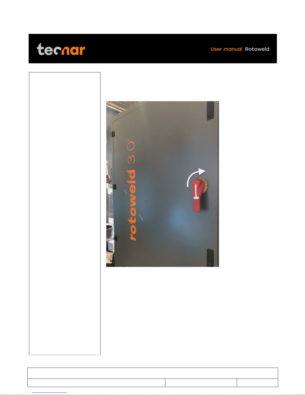
5 STARTUP
Turn on the main power switch located on the back of the master positioner
(figure 8).
FIGURE 8 MAIN POWER SWITCH

This document contains information considered proprietary and confidential to Tecnar Automation Ltd
40101-00020-00– Rev 1.2
Revision date: 2017-07-31
Page 18 of 48
!
Turn on the on/off switch (key) located on the left had side of the pendant
(Figure 9).
FIGURE 9 ON/OFF SWITCH

This document contains information considered proprietary and confidential to Tecnar Automation Ltd
40101-00020-00– Rev 1.2
Revision date: 2017-07-31
Page 19 of 48
!
Calibration screen will display (Figure 10).
FIGURE 10 CALIBRATION SCREEN WILL DISPLAY
Proceed to calibration for all axes by holding down the TORCH UP knob on
the pendant. Wait until the “Calibration complete” message appears on the
screen to release the knob (Figure 11).
FIGURE 11 TORCH UP
If one or more axis fails to calibrate, refer to arm error calibration on page 19
This document contains information considered proprietary and confidential to Tecnar Automation Ltd
40101-00020-00– Rev 1.2
Revision date: 2017-07-31
Page 20 of 48
!
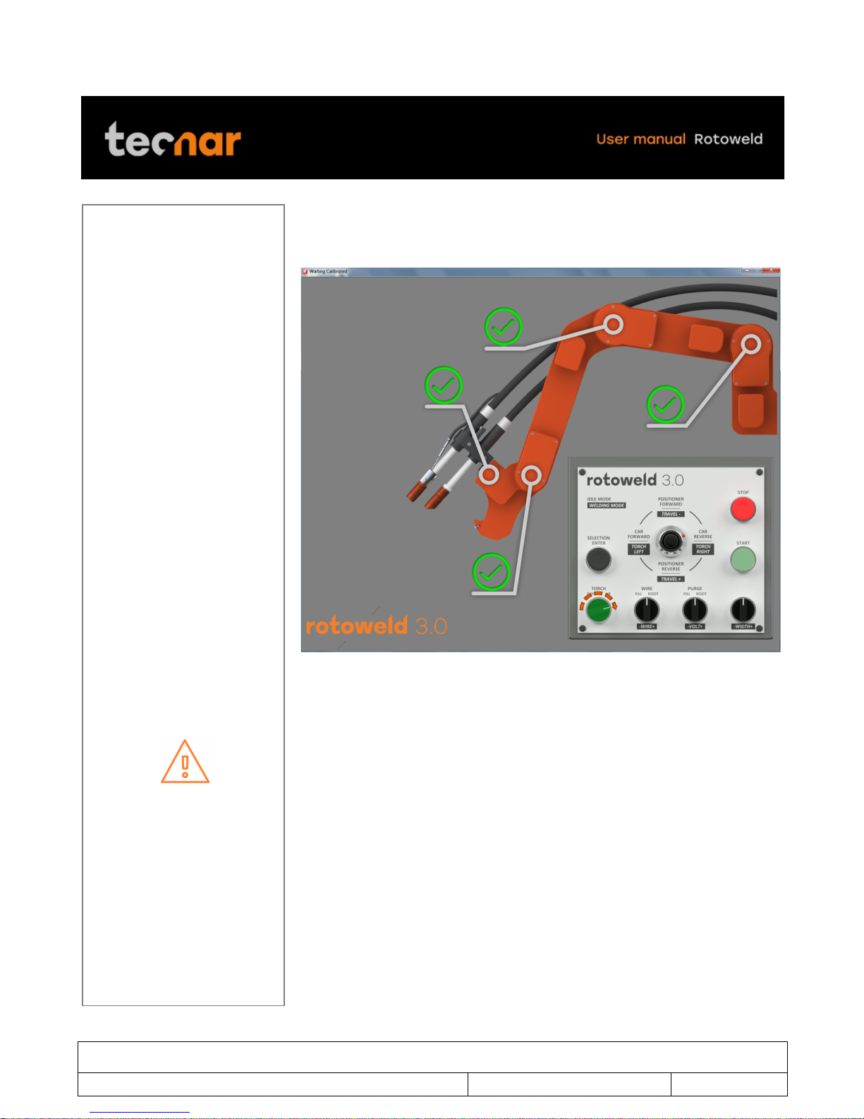
When calibration is completed, all axes will turn green with a check symbol
(Figure 12). The Rotoweld is then ready and you will be directed to the main
screen (Figure 13).
FIGURE 12 CALIBRATION IS COMPLETED
In case one or more axis don’t calibrate normally, press the stop knob 3 times
to clears the errors, try again to calibrate.
If error occurs again, you must shutdown the entire machine to clears all PLC
errors. Before proceeding to a complete shutdown of the Rotoweld, please
connect a mouse to the computer and shut down the computer properly (in
Microsoft Windows click on start button in the left down corner and click on
shutdown and select shutdown. With the computer properly turned off you
can proceed to the shutdown of the Rotoweld via the main power switch
(figure 8 on page 14). Wait 15 seconds after shutdown, then power ON the
machine again.
Other manuals for Rotoweld 3.0
1
Table of contents
Popular Welding System manuals by other brands

EWM
EWM Taurus 400 Basic TDG operating instructions

Lincoln Electric
Lincoln Electric POWER WAVE 405 IM746 Operator's manual

Comparc
Comparc ALPHA TIG 252 - DP owner's manual

Weco
Weco Discovery 300 instruction manual

widos
widos MAXIPLAST Working Instructions Translation

Red-D-Arc Welderentals
Red-D-Arc Welderentals DX350 Operator's manual


