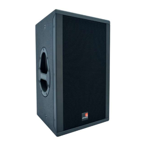
Tecnare Sound Systems V Series User manual

Keep these important operating instructions.
Check www.tecnare.com for updates.
Operation Manual
V-10, V-12, V-15
Multi-purpose Loudspeaker
V Series
Version 2.0


Operation Manual
www.tecnare.com V Series | rev.
2.00
2
General Information
V Series Operation Manual
Ver.: 2.0_UK 01/2017
©EXEL ACOUSTICS SL; all right reserved
The information contained in this manual has been
carefully checked for accuracy, at the time of going to
press, however no guarantee is given with respect to
the correctness.
Exel Acoustics SL accepts no responsibility for any
errors or inaccuracies that may appear in this manual
or the products and software described in it. Technical
specifications, dimensions, weights and properties do
not represent guaranteed qualities. As manufacturers
we reserve the right to make alterations and
modifications within the framework of legal provisions,
as well as changes aimed at improving quality.
EXEL ACOUSTICS SL
CL Encinar, 282 – Pol. Ind. Monte Boyal
45950 Casarrubios del Monte (Toledo) Spain
Phone: (+34) 918 170 110 Fax:
e-mail: support@tecnare.com www.tecnare.com

Operation Manual
www.tecnare.com V Series | rev.
2.00
3
IMPORTANT SAFE INSTRUCTIONS
Before using our product, be sure to carefully read the
manual and safe Instructions. Keep this document with
the device all time.
1 Read these instructions.
2 Keep these instructions.
3 Heed all warnings.
4 Follow all SAFETY INSTRUCTIONS as well
DANGER and OBLIGATION warnings.
5 Only use attachments / accessories
specified by the manufacturer.
6 Use only with the cart, tripod, bracket or
table specified by the manufacturer, or sold
with the apparatus. When a cart is used, use
caution when moving the cart / apparatus
combination to avoid injury from tip-over.
7 If the equipment is used in a manner not
specified by the Exel Acoustic, the protection
by the equipment may be impaired.
8 Read all the Product Information document
before exploiting the system.
9 Read the Rigging Manual before installing
the system. Use the rigging accessories
described in the rigging manual an follow the
associated procedures.
CAUTION: Rigging should only be done by experience
professionals.
10 This speaker enclosure is capable of
creating a strong magnetic field. Please use
caution around the enclosure with data
storage devices such as phones, computers
or hard drivers.
11 Handles are for moving the system only.
12 Beware of sound levels. Never stand in the
immediate vicinity of loudspeaker driven at
high level. Professional loudspeaker
systems are capable of causing a sound
pressure level (SPL) detrimental to human
health. Hearing damage can also occur with
prolonged exposure to sound: 8h at 90
dB(A), 30 min at 110 dB(A), less than 4 min
at 130 dB(A) Source: European Directive
relating to the assessment and management
of noise 2002/49/CE
13 When setting up the loudspeaker or
loudspeaker stand, make sure they are
standing on a firm surface. If you place
several enclosures on top of one another,
use straps to secure them against
movement.

Operation Manual
www.tecnare.com V Series | rev.
2.00
4
SYMBOLS USED
Important operating
instructions
Additional
information
OBLIGATION.This
instructions must
be strictly followed
Pour indequer important
Instructions
Information
complémentaire
Obligation. Cela
doit être
strictement
instructions Suivi
Wichtige
Betriebsanweisung
oder
Gebrauchsanleitung
sanleitung
Informationen.
Zusätzliche
Informationen
Pflicht. Diese
Anweisungen
müssen strikt
befolgt
Importantes
instrucciones operativas
Información
complementaria
Obligación. Estas
instrucciones
deben ser
estrictamente
seguidas

Operation Manual
www.tecnare.com V Series | rev.
2.00
5
DECLARACIÓN DE CONFORMIDAD
DECLARATION OF CONFORMITY
EXEL ACOUSTICS SL
CL Encinar, 282. Polígono Industrial Monte Boyal. 45950 – Casarrubios del Monte (Toledo),
España (Spain).
Declara que los productos V Series y sus respectivas opciones, cumple con las Directivas:
Declare under our sole responsibility that devices in the V Series range of products, comply
with relating Directives:
(1) Directiva de Baja Tensión - 2006/95/CE
(2) Directiva de Compativilidad Electromagnética - 2004/108/CE
(3) Directiva RoHS - 2011/65/UE
(4) Directiva RAEE - 2012/19/UE
(1) Low Voltaje Directive 2006/95/CE
(2) EMC 2004/108/CE
(3) RoHS Directive 2011/65/UE
(4) WEEE Directive 2012/19/UE

Operation Manual
www.tecnare.com V Series | rev.
2.00
6
Table of Contents
IMPORTANT SAFE INSTRUCTIONS......................................................................................3
DECLARACIÓN DE CONFORMIDAD.....................................................................................5
1Introduction ...................................................................................................................7
1.1 Welcome to Tecnare ................................................................................................7
1.2 Overview..................................................................................................................8
1.3 The V Series Loudspeaker .......................................................................................9
1.4 Connections ...........................................................................................................10
1.5 Processing and Amplification..................................................................................11
2Loudspeakers Configurations ....................................................................................12
2.1 Configurable Asymmetrical Horn ............................................................................12
2.2 Front of House configuration...................................................................................12
2.3 Stage Monitor Configuration ...................................................................................13
2.4 Rotating the Horn ...................................................................................................14
3Amplifier selection for V Series.................................................................................15
3.1 Recommended Amplifier Power..............................................................................15
3.2 Recommended Speaker Cables .............................................................................15
4Recommended configuration for V Series ...............................................................17
5Flying and Suspension................................................................................................20
5.1 Important Safety Warning.......................................................................................20
5.2 Tripod Use .............................................................................................................20
5.3 Flying .....................................................................................................................20
6Technical specifications..............................................................................................24

Operation Manual
www.tecnare.com V Series | rev.
2.00
7
1Introduction
1.1 Welcome to Tecnare
Thank you for choosing the high-quality Tecnare®V Series System “Made in Spain” from
EXEL ACOUSTICS SL.
Please spare a little time to study the contents of this manual, so that you obtain the best
possible performance from this unit.
All Tecnare®products are carefully engineered for world-class performance and reliability.
If you would like further information about this or any other Tecnare®product, please
contact us. We look forward to helping you in the near future.
As part of a continuous evolution of techniques and standards, Exel Acoustics
SL as manufacturer of Tecnare®products reserve the right to change the specifications
of its products and the content of its documents without prior notice.
Updates and supplementary information are available on the Tecnare®website:
http://www.tecnare.com
Tecnare Technical Support is available at:
(T): +34 918 170 110 - +34 918 171 001
(e-mail): supp[email protected]m
Thank you again for placing your confidence in Tecnare®products.

Operation Manual
www.tecnare.com V Series | rev.
2.00
8
1.2 Overview
VSeries means Versatile loudspeakers, ideally suited to all kinds of live performance,
including stage monitoring.
V Series are synonymous with exceptional sound quality and reliability and are designed for
the most discerning musician and audio systems contractor.
V10, V12 and V15 are suitable for distributed sound reinforcement in theatre, congress
centre, concert hall, trade show, corporate A/V, houses of worship, club, or television
applications.
When used with some Tecnare®Subwoofer can also be used for side fill, drum fill or small-
to-medium format front-of-house (F.O.H.) applications. In addition to these applications, the V
Series is specifically optimized for use as a high-performance stage monitoring solution.
The V Series system range and components are formed from:
V-10, passive/active compact loudspeaker, 90ºH x 60ºV, 52Hz to 20kHz;
V-12, passive/active multipurpose loudspeaker, 55º to 100ºH x 60ºV, Rotatable
horn, 48Hz to 17kHz;
V-15 passive/active compact High-Power loudspeaker, 55º to 100ºH x 60ºV,
rotatable horn, 42Hz to 17kHz;
All models are equipped with a pole mount socket and multiple M8 and M10
attachment points and additional installation-friendly features and utilize a rugged grille design
and system appearance suitable for nearly all indoor environments.
The line will include a optionally U-brackets, ceiling brackets and a wall mount bracket
accessory that provides safe, flexible and simple means of installing for all full-range models in
fixed installation as well as in touring applications.

Operation Manual
www.tecnare.com V Series | rev.
2.00
9
1.3 The V Series Loudspeaker
FEATURES
V-10
The Tecnare V-10 loudspeakers are comprised
of:
One 10-inch driver
one 1-inch HF compression driver.
Built-in rigging points (eyebolt) and top
rigging track
A Pole mount socket
The V-10 is a lightweight 2-way passive
loudspeaker that used a 10” low-mid
frequency transducer in a bass-reflex
cabinet and a 1” compression driver on a
rotatable horn. The internal passive
crossover network uses a custom filters.
V-12
The Tecnare V-12 loudspeakers are comprised
of:
One 12-inch driver
one 1.4-inch HF compression driver
on a rotatable CD horn
Built-in rigging points (eyebolt) and top
rigging track
A Pole mount socket
The V-12 is a multipurpose 2-way passive
loudspeaker that used a 10” low-mid
frequency transducer in a bass-reflex
cabinet and an one 1.4” compression driver
on a rotatable horn. The internal passive
crossover network uses a custom filters.
V-15
The Tecnare V-15 hIgh-power loudspeakers are
comprised of:
One 12-inch driver
one 1.4-inch HF compression driver on
a rotatable CD horn
Built-in rigging points (eyebolt) and top
rigging track
A Pole mount socket
The V-15 is a high-power 2-way passive
loudspeaker that used a 15” low-mid
frequency transducer in a bass-reflex
cabinet and a 1.4” compression driver on a
rotatable horn. The internal passive
crossover network uses a custom filters.

Operation Manual
www.tecnare.com V Series | rev.
2.00
10
1.4 Connections
V Series loudspeakers utilize Neutrik®SpeakON®connectors. There are two NLT4
connectors on the rear of each V Series enclosure. These connectors mate with Neutrik®NL-4
or NL-4 compatible in-line cable connectors. The pins 1+/1- of both connectors are wired in
parallel to link multiple loudspeakers on a single amplifier output. Remember that parallel
connection reduces the total impedance (Ω) seen by the amplifier.
The total impedance of loudspeaker connected in parallel must not drop below the
minimum operating impedance of the amplifier.
The following subsections describe the electrical connections of V-10, V-12 and V-15.
IN speakON®point
1+ 1- 2+ 2-
Connection IN +
IN - NC
NC
The V Series uses the pin assignment 1+/1+.
Using one as the input, the second connector allows for direct connection to a second
cabinet.
Fig.1.- Wiring diagram

Operation Manual
www.tecnare.com V Series | rev.
2.00
11
1.5 Processing and Amplification
Only operate Tecnare loudspeaker with a correctly configured Tecnare preset. Tecnare
offer a complete solution that guarantees the highest level of performance. A complete range of
controllers, amplified and amplified controller with DSP are available to get this objective.
Otherwise, there is a risk of damaging the loudspeaker components.
1.5.1 Processing
There are two options using our digital controllers. Our DP2696 or DP4896. The options
vary depending on the final application. Refer to DP2696 or DP4896 user manual.
Preset for DP Series processors have been developed for the V Series.
You may obtain the settings from the DP Series at http://www.tecnare.com website.
1.5.2 Amplification
To power V Series, Tecnare recommends amplifiers with the power ratings enough to
feed the loudspeakers. For high power or live applications, it is recommended to
oversize the amplifiers relative to the nominal AES output of the loudspeakers. A lower
power amplifier will not reduce the chances of driver damage due to over-excursion,
and may actually increase the risk of thermal damage due to sustained clipping.
In certain specific cases it is possible to slightly under-power the subs or loudspeakers
as long as the amplifier will not be driven to its limits.
In any case, the Tecnare processors should be deployed in front of the amp to ensure
that the amplifiers to not go into clip.
The DP4896 processors also include:
- Virtual Xover Limiter for passive systems
- Thermal protection from power surges or overload
- Xmax Excursion displacement protection
The T20-44 amplifier is the ideal companion for maximum performance of the V Series
loudspeakers. This amplifier controller with DSP offer a complete both preset and
protection solution for any application.

Operation Manual
www.tecnare.com V Series | rev.
2.00
12
2Loudspeakers Configurations
2.1 Configurable Asymmetrical Horn
The V Series loudspeakers are designed for standing, vertical and horizontal operation. A
variety of accessories is available from Tecnare®to securely attach the loudspeaker, e.g. on
stands or suspended horizontally or vertically from trusses and motor lifts.
In some situations, it may be advantageous to switch the coverage of the high frequency
range. For this purpose the Asymmetrical Dispersion Constant Directivity horn is an important
feature of the V Series. The horn can be rotated in four different positions and can be useful for
specialized applications such as complex arrays, systems designed with CAD software and
stage monitoring.
Ensure that the loudspeakers are securely attached to prevent personal injury
and property damage.
NOTE
TECNARE recommends using only the accessories specified by TECNARE to
secure the loudspeakers.
2.2 Front of House configuration
Good coverage of audiences often requires a conflicting combination of wide coverage
("short-throw") for the closest listeners (below cabinet axis) and narrow coverage ("long-throw")
for distant areas (on or above axis). The V-12 and V15 loudspeaker horizontal horn coverage
varies from "short-throw" to "long-throw" along the vertical axis to precisely match these
practical requirements in a single system. For the majority of applications, the asymmetrical
horn should be used with its "wide" dispersion side directed towards the floor, but all four
cabinet orientations are usable.

Operation Manual
www.tecnare.com V Series | rev.
2.00
13
The horn of V-10 loudspeaker is mounted at the factory in such a way that the
horizontal coverage is 90º and the vertical coverage is 60º. You can easily re-orient the V-10
rotatable horn to its 60º x 90º.
2.3 Stage Monitor Configuration
For stage monitors the required coverage is always wider when performers are close to the
wedge (above the horn axis) than when they move away from it (below the horn axis). For floor
monitor use the horn must be rotated with its "wide" dispersion side directed towards the top of
the cabinet in wedge position as shown in the below figure.
The specific dispersion pattern, the HF driver and the very high power handling all
contribute to the exceptional performance of the V Series as a wedge monitor.

Operation Manual
www.tecnare.com V Series | rev.
2.00
14
2.4 Rotating the Horn
Access to the horn for configuration and checking is easily made by removing the front
grille.
1. Place the V Series loudspeaker with the wedge inclined toward you with the front grill
facing up. Ensure that the working surface is clean with a non-slip finish.
2. To remove the front grill of the loudspeaker, use a 4 mm hex key. Remove the six fixing
screws placed at both side loudspeaker enclosures.
3. Remove the two brackets carefully that holding the grille.
4. Release the four screws of the horn using a hex key. Pull the horn and the compression
driver upward out of the loudspeaker enclosure.
5. Check that the seal between the enclosure and horn is properly seated.
6. Rotate the horn carefully on the desired position and reinsert the horn and driver back
into the recess. Screw it onto the enclosure using medium-strength thread locker.
7. Screw the front grill back on.
Fig.2.- Change of configuration on V-12 and V-15
Fig.3.- Change of configuration on V-10

Operation Manual
www.tecnare.com V Series | rev.
2.00
15
3Amplifier selection for V Series
3.1 Recommended Amplifier Power
Tecnare recommends amplifiers in agreement with table below:
Model Full-Range/ Parallel Model recommended
V-10 200 to 700 W @ 8Ω PA900/PA2100/PA4.450/T-Series
V-12 300 to 1.000 W @ 8Ω PA900/PA2100/PA3000/PA4.450/T-
Series
V-15 400 to 1.100 W @ 8Ω PA900/PA2100/PA3000/PA4.450/T-
Series
3.2 Recommended Speaker Cables
Choosing the right wire gauge for your installation is unmost importance to ensure you will
get the maximum potential of your system.
The two primary things resistance affects in the amplifier-to-loudspeaker connection are:
insertion loss and damping factor, both of which are dependent upon cable resistance. Too
small a cable section will increase both its serial resistance and its capacitance; this reduces the
electrical power delivered to the loudspeaker and can also induce response (damping factor)
variations.
INSERTION LOSS
Insertion loss is the measure of the loss of load power at the speaker due to excessive
resistive losses of the cable or any additional component attached between the amplifier and
the loudspeaker. We typically express this loss in decibels (dB) using the following formula:
20 log Rload
IL
Rload Rcable
DAMPING FACTOR
Damping factor is a ratio of rated loudspeaker impedance (ZL) to the source impedance
(Zs). In this case our source impedance is (Rcable + Ramplifier).
Damping Factor = ZL/ZS
The table below indicates the cable valor recommended by Tecnare®.
Recommended maximun length
cable cross-section 8 Ω 4 Ω 2 Ω
mm² SWG AWG m ft m ft m ft
2,5 15 13 30 100 15 50 10 33
4 13 11 50 160 25 80 17 53
6 11 9 74 240 37 120 25 80
10 9 7 120 390 60 195 40 130

Operation Manual
www.tecnare.com V Series | rev.
2.00
16
IMPORTANT
Long speaker cables induce capacitive effects – up to hundreds of pF depending on the
quality of the cable - with a low-pass effect on high frequencies. If long speaker cables
must be used, ensure that they do not remain coiled while in use.
This manual suits for next models
3
Table of contents
Other Tecnare Sound Systems Speakers manuals


