TECNARE EXEL ACOUSTICS SL ARRAY Series User manual

Keep these important operating instructions.
Check www.tecnare.com for updates.
Rigging Assembly Guide
ARRAY Series
CLa21/SW-18VR
Version 1.0

1

Rigging Assembly Guide
2
General Information
CLa21 / SW-18VR Rigging Assembly
Ver.: 1.0_UK 04/2017
©EXEL ACOUSTICS SL; all right reserved
The information contained in this manual has been
carefully checked for accuracy, at the time of going to
press, however no guarantee is given with respect to
the correctness.
Exel Acoustics SL accepts no responsibility for any
errors or inaccuracies that may appear in this manual
or the products and software described in it. Technical
specifications, dimensions, weights and properties do
not represent guaranteed qualities. As manufacturers
we reserve the right to make alterations and
modifications within the framework of legal provisions,
as well as changes aimed at improving quality.
EXEL ACOUSTICS SL
CL Encinar, 282 – Pol. Ind. Monte Boyal
45950 Casarrubios del Monte (Toledo) Spain
Phone: (+34) 918 170 110 Fax:
e-mail: support@tecnare.com www.tecnare.com

3
IMPORTANT SAFE INSTRUCTIONS
Before using our product, be sure to carefully read the manual and safe Instructions. Keep this document with the device all
time.
1 Read these instructions.
2 Keep these instructions.
3 Heed all warnings.
4 Follow all SAFETY INSTRUCTIONS as well
DANGER and OBLIGATION warnings.
5 Only use attachments / accessories
specified by the manufacturer.
6 SAFETY STATEMENT FOR RIGGING. This
Statement assumes that the owners and/or
users are familiar with the rigging techniques
and safety recommendations outlined in this
manual. Many issues of crucial concern,
such as the determination of
appropriateness and condition of venue
rigging points, cannot be addressed here.
Therefore, the user must assume all
responsibility for the appropriate use of
Rigging systems in any particular location or
circumstance.
7 PERSONNEL HEALTH AND SAFETY.
During installation and set-up personnel
should wear protective headgear and
footwear at all times. Under no
circumstances personnel should climb on
the loudspeaker assembly.
8 INSPECTION AND MAINTENANCE. The
rigging systems are an assembly of
mechanical devices, and are therefore
subject to wear and tear over prolonged use,
as well as damage from corrosive agents,
extreme impact, or inappropriate use.
Because of the safety issues involved, all
system components must be inspected
before use in order to detect any possible
defects.
9 LOAD RATING AND SPECIFICATIONS.
Load capacity and setup safety limits when
flying or stacking a loudspeaker assembly
should be strictly followed according to the
instructions outlined in this manual.
10 LOCAL REGULATIONS. The suspension of
large, heavy objects in public places is
subject to numerous laws and regulations at
the national/federal, state/provincial, and
local levels. It is the user’s responsibility to
verify that any overhead suspension of
TECNARE systems has been made in
accordance with all applicable local
regulations in any particular circumstance or
venue conforms to all applicable laws and
regulations in force at the time.
11 FLYING A LOUDSPEAKER SYSTEM
Always verify that nobody is standing
underneath the loudspeaker assembly when
it is being raised. As the system is being
raised check each individual component to
make sure that it is securely fastened to the
component above. Never leave the system
unattended during the installation process.
As a general rule, EXEL ACOUSTICS
recommends the use of safety slings at all
times.
12 STACKING A LOUDSPEAKER SYSTEM.
Do not ground stack the system on unstable
ground or platform. If the system is ground
stacked on a structure, platform, or stage
always check that the latter can support the
total weight of the system. As a general rule,
EXEL ACOUSTICS recommends the use of
safety straps at all times
13 When a loudspeaker assembly is deployed
in an open air environment, wind effects
should be taken into account. Wind can
produce dynamic stress to the rigging
components and suspension points. If the
wind force exceeds 6 B (Beaufort scale) it is
highly recommended to lower down and/or
secure the loudspeaker assembly.
14 REPLACEMENT PARTS. Any component
found to be defective, or any safety-related
component you even suspect might be
defective, should be replaced with the
equivalent, approved part. Parts specific to a
rigging system should be ordered directly
from Exel Acoustics. No attempt should be
made to substitute what appears to be
equivalent or “mostly the same” generic
replacements. Therefore, EXEL
ACOUSTICS is not responsible for problems
caused by components that were not
supplied by EXEL ACOUSTICS.

Introduction
4
SYMBOLS USED
Important operating
instructions
Additional
information
OBLIGATION.This
instructions must
be strictly followed
Pour indequer important
Instructions
Information
complémentaire
Obligation. Cela
doit être
strictement
instructions Suivi
Wichtige
Betriebsanweisung
oder
Gebrauchsanleitung
sanleitung
Informationen.
Zusätzliche
Informationen
Pflicht. Diese
Anweisungen
müssen strikt
befolgt
Importantes
instrucciones operativas
Información
complementaria
Obligación. Estas
instrucciones
deben ser
estrictamente
seguidas

Introduction
5
DECLARACIÓN DE CONFORMIDAD
DECLARATION OF CONFORMITY
EXEL ACOUSTICS SL
CL Encinar, 282. Polígono Industrial Monte Boyal. 45950 – Casarrubios del Monte (Toledo),
España (Spain).
Declara que los siguientes productos:
▪Multipurpose grid THV21-18VR
▪Angle arm extensions CLa21-ANGEXT
▪Pull-back frame CLa21 Pull-Back
▪Rigging Kit TRK-18VR
cumplen con las directivas:
Declare under our sole responsibility that devices
▪Multipurpose grid THV21-18VR
▪Angle arm extensions CLa21-ANGEXT
▪Pull-back frame CLa21 Pull-Back
▪Rigging Kit TRK-18VR
comply with relating Directives:
(1) Directiva 2006/42/CE relativa a las máquinas.
(2) Norma UNE-EN ISO 12100:2012 Relatíva a la seguridad de las máquinas.
(3) RD 1644/2008
(1) Machinery Directive 2006/42/EC
(2) Mechanical Safety UNE-EN ISO 12100:2012 (Applied in Spain)
(3) RD 1644/2008 (applied in Spain)

Table of Contents
6
Table of Contents
IMPORTANT SAFE INSTRUCTIONS......................................................................................3
DECLARACIÓN DE CONFORMIDAD.....................................................................................5
1Introduction ...................................................................................................................7
1.1 Welcome to Tecnare®...............................................................................................7
1.2 CLa21 and SW-18VR System ..................................................................................8
2THV21-18VR MULTIPURPOSE GRID .........................................................................11
2.1 THV21-18VR GRID DIMENSIONS .........................................................................12
3ASSEMBLING AN ARRAY ............................................................................................13
3.1 Modelling and inspection ........................................................................................13
3.2 Grid orientation for Flown Arrays ............................................................................13
3.3 Guide links .............................................................................................................15
3.4 Flying a CLa21 standalone array ............................................................................22
3.5 Flying a SW-18VR/CLa21 mixed array or SW-18VR standalone array ....................27
4Groundstacking with the THV21-18VR Grid............................................................30
4.1 Configuring guide link arms for THV21-18VR..........................................................31
4.2 Grid Orientation and Groundstacks.........................................................................32
4.3 Adding Groundstack tilt with the optional ANGEXT arm ..........................................33
4.4 Groundstacking CLa21 on SW-18VR......................................................................35
5Pull-back PB-CLa21.....................................................................................................37
5.1 Groundstacking CLa21 on SW-18VR......................................................................38
6TWD21 Wooden transport Dolly................................................................................39
6.1 TWD21 wooden dolly dimensions...........................................................................40
6.2 Safety guideline for the TWD21 wooden dolly.........................................................41
7TWD-18VR Wooden transport Dolly.........................................................................42
7.1 TWD-18VR wooden dolly dimensions.....................................................................45
7.2 Safety guideline for the TWD21 wooden dolly.........................................................46
8Service, Inspection & Maintenance ..........................................................................47
8.1 General Service .....................................................................................................47
8.2 Replacement components ...................................................................................... 47
8.3 Contacting Tecnare ................................................................................................47

Operation Manual
7
1Introduction
1.1 Welcome to Tecnare®
Thank you for choosing the high-quality Tecnare®Sound System “Made in Spain” from
EXEL ACOUSTICS SL.
Please spare a little time to study the contents of this manual, so that you obtain the best
possible performance from this unit.
All Tecnare®products are carefully engineered for world-class performance and reliability.
If you would like further information about this or any other Tecnare®product, please
contact us. We look forward to helping you in the near future.
As part of a continuous evolution of techniques and standards, Exel Acoustics
SL as manufacturer of Tecnare®products reserve the right to change the specifications
of its products and the content of its documents without prior notice.
Updates and supplementary information are available on the Tecnare®website:
http://www.tecnare.com
Tecnare Technical Support is available at:
(T): +34 918 170 110 - +34 918 171 001
(e-mail): supp[email protected]m
Thank you again for placing your confidence in Tecnare®products.

Rigging Assembly Guide
8
1.2 CLa21 and SW-18VR System
This assembly guide document the rigging and transport options THV21, CLA21_ANGEXT,
CLA21 PULLBACK, TTF-208-18VR-21, TWD-21 and TWD-18VR available for CLa21 and
SW18VR in the form of flown or stacked vertical arrays.
The system approach developed by EXEL ACOUSTICS for CLa21 and SW-18VR consists
of the elements needed to fully take advantage of the possible configurations and optimize the
system. The main components of the system are:
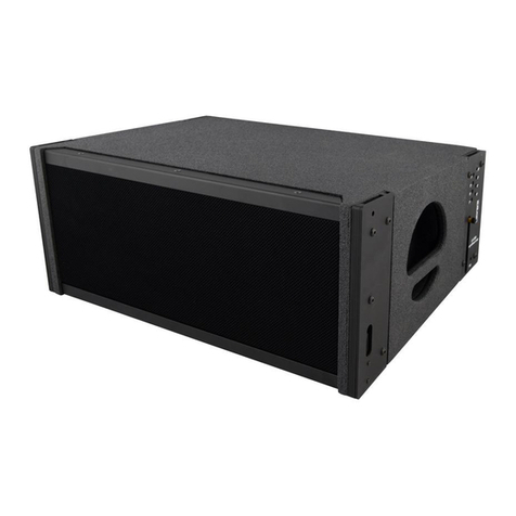
▪CLa21: Compact Curvilinear Array loudspeaker
▪SW-18VR: Compact High-Power Bass Module
▪THV21-18VR: Multipurpose grid
▪CLA21_ANGEXT: Angle arm extensions for stacked CLa21 and/or SW18VR
▪CLA21 PULLBACK: Pull-back frame accessory for CLa21 array pull-back
configuration
▪TTF-208-18VR-21: Transition frame that allows CLa208s to be flown below
CLa21/SW-18VR arrays.
▪TWD-21: Wooden transport dolly from CLa21. Will transport up to 4 CLa21
▪TWD-18VR: Wooden transport dolly from SW-18VR. Will transport up to 3 SW-
18VR
▪TRK-18VR: Rigging hardware kit from SW-18VR
▪T-44/48: Advanced System Amplifier
▪System Engineer: Remote control software for amplifier

Operation Manual
9
Rigging Example

Rigging Assembly Guide
10

Operation Manual
11
2THV21-18VR MULTIPURPOSE GRID
The THV21-18VR grid is made of steel and has been designed to fly or stack mixed arrays
of CLa21s and SW18VRs enclosures without transition hardware.
The THV21-18VR is a square frame fitted with the following elements:
▪Four quick-release pins
▪Four rotating Guide-link
The THV21-18VR grid accommodates a variety of pickup configurations with its 21 center
pickup points and . To add tilt to the array, attach motors to the front and rear of the center point
plate. If just one motor is available, attach it to one of the 19 center pickup points offset from the
center of the grid to achieve the desired tilt. The grid can also be oriented to provide either
maximum array downtilt or maximum array uptilt
Fig.1 THV21-18VR grid
CAUTION: Always use the quick-release pins included with the THV21-18VR grid to
secure the attached CLa21 or SW18VR. Do not use the magnetic quick-release pins included
with CLa21 or the SW-18VR in the grid as they are shorter and will not lock in place.
CAUTION: Always use properly rated rigging hardware. The THV21-18VR have holes in
the center pickup point plate of 24mm diameter and you should use an adequate shackles for
its pickup points with enough load capacity.
Rotating
Guide link
Pickup Points
Quick release
pins

Rigging Assembly Guide
12
2.1 THV21-18VR GRID DIMENSIONS
Fig.2 THV21-18VR Grid Dimensions

Operation Manual
13
3ASSEMBLING AN ARRAY
3.1 Modelling and inspection
Before installing the systems it is a good idea to run a simulation with EASE Focus software
which will assist the user to:
▪Determinate the number of CLa21 enclosure
▪Calculate the THV21-18VR site angle and the splay angles
▪Check the mechanical conformity of the system.
It is extremely important to assure that each and every one of the structures involved in the
process hanging are capable of supporting a superior load than that of the complete system. As
an extra precaution, careful inspection of the attachment points is advised before flying,
particularly in older venues or those hosting frequent events using large sound and lighting
systems.
Inspection is the next step. Key components must be inspected before each use. Such
inspection includes examination of all load-bearing components for any sign of undue wear,
twisting, buckling, cracking, rusting, or other corrosion.
Particular attention should be given to screws, bolts, and other fasteners to make certain
the fittings are tight and secure. Metal seams and welds should be examined for any sign of
separation or deformation.
Rigging should be carried out by expert familiar with the way the system function and their
characteristics.
3.2 Grid orientation for Flown Arrays
The THV21-18VR grid can be oriented to locate the array’s center of gravity closer to the
front or rear of the grid, to achieve a few more degrees of downtilt or uptilt for flown arrays. The
grid’s orientation is also important when accommodating groundstacks with downtilt or uptilt
(see “Grid Orientation and Groundstacks” on page 32).
To add tilt to the grid, you can attach two motors to the front and rear of the centre
pickup point plate. If just one motor is available, attach it to one of the 19 centre pickup
points offset from the centre of the grid to achieve the desired tilt.

Rigging Assembly Guide
14
THV21-18VH GRID ORIENTED FOR MAXIMUM ARRAY DOWNTILT
When the THV21-18VR grid is oriented forward with the attached loudspeaker near the
front of the grid, the array’s centre of gravity is located closer to the front of the grid, thereby
allowing the rear pickup points to achieve maximum array down-tilt.
Fig. 3 THV21-18VR Grid oriented for maximum array downtil
THV21-18VH GRID ORIENTED FOR MAXIMUM ARRAY UPTILT
When the THV21-18VR grid is oriented rearward with the attached loudspeaker near
the rear of the grid, the array’s center of gravity is located closer to the rear of the grid, thereby
allowing the front pickup points to achieve maximum array uptilt.
Fig. 4 THV21-18VR Grid oriented for maximum array Uptilt

Operation Manual
15
3.3 Guide links
CLA21 GUIDE LINKS ARM
CLa21 is equipped with four captive guide links arms that link to adjacent units of CLa21 or
SW-18VR in flown and groundstacked arrays. Located at the top corners of the cabinet, the
guide links arms extend up and into the link slots of the cabinet above it (or into the link slots of
the THV21-18VR). The links extend and retract with recessed knobs and are secured with
quick-release pins: one each in the top and bottom cabinet.
CLa21 loudspeaker ships with eight quick-release magnets pins.
Fig 5 CLa21 Guide link arms with quick release pins
CAUTION: CLa21 guide links arms must be secured with the included quick-release
magnets pins. At not time should the weight of the enclosure rest on the knobs when the link
are fully extended (without the pins inserted). The purpose of Knobs of guide links arms is only
extend and retract the guide links arms.

Rigging Assembly Guide
16
CLA21 SPLAY ANGLES
Front guide links arms attach at splay angles of 0 or +4 degrees. However, the front guide
links should almost always be attached at 0 degrees, to ensure that coverage between linked
cabinets is continuous. When attached at 0 degrees, the front guide links arms act as a pivot
point between the linked CLa21s, with the splay angle between the units determined by the rear
guide link positions. In this way have angles available from 0 to 8 degrees.
Fig 6 CLa21 Guide link arms setting at 0 degrees
When attached at +4 degrees, the front guide links arms add 4 degrees to the splay angle
configured with the rear guide links, making it possible to achieve splay angles of 9 to 13
degrees. To stow the front guide Links, move them all the way down to STOW and pin them.
CLa21 Front guide link label with angle

Operation Manual
17
Wide splayed angles of 9 to 15 degrees should only be used for downfill coverage, or for
steering coverage away from structures like balconies.
The rear guide links arms determines the vertical splay angle (whether stacked or flown),
as a function of the hole where the pin is attached. Rear guide links arms attach at splay angles
of 0 to 9 degrees
Stack or flown mode is determined by the position in which the guide arm is attached to
the upper cabinet.
For flying the boxes and defining the splay angle, the pin must be inserted in the sliding slot of
guide links arms whereas for stacking, the pin goes through the fixed hole of the guide links
arms. For flown, after the stack is lifted, the loudspeakers rotate on the axis of the front link
arms and the rear guide link arms slide into position as the weight of the of the loudspeakers
causes the cabinets to shift
.
Fig. 8 Rear guide link arms (A) Stack Mode (B) Flown Mode
To aid the setting of guide links arms, each hole is labelled with the splay angle between
cabinets. As the links are moved down, the splay angle increases. To fit the guide links arms
into the hole, highly resistant 10mm quick-release magnet pins are used.
To stow the rear guide links arms, move them all the way down to STOW and pin them to
the 0 degree pin position.
Fig. 9 Rear guide link label and pinning position
A
B

Rigging Assembly Guide
18
When the front links guide are attached at +4 degrees, the pins must be inserted in the
holes which the splay angles are labeled in brackets.
The splay angles listed on the guide link labels are for relative angles between the center
axes of the linked units. For example, setting the guide links to 5 degrees yields a 5-
degree downtilt of the lower unit to the upper unit. How the loudspeakers relate to the
floor, stage, and seating angles in the venue depends on the orientation of the grid, the
angles of the loudspeakers in the array above them, and other factors. EASE Focus
prediction software should be used to calculate optimum splay angles for loudspeakers
and to predict coverage patterns for arrays.
CAUTION: CLa21 guide links arms must be secured with the included quick-release
magnets pins. At not time should the weight of the enclosure rest on the knobs when the link
are fully extended (without the pins inserted). The purpose of Knobs of guide links arms is only
extend and retract the guide links arms.
CLA21 SPLAY ANGLES FOR TOP FLOWN CABINETS
When flying CLa21 below THV21-18VR grid, splay angles of -6 to 7 are possible for top
cabinet with the following guide links arms configurations.
The holes which the splay angles are labeled in brackets.
When flying CLa21s from the THV21-18VR It is recommended to select the 6º angle on
the Cla21 intended to be linked to the THV21-18VR. In this way the Cla21 axis will be
parallel to the THV21-18VR
CAUTION: To link the THV21-18VR and Cla21 the quick-release pin-lock must always be
done by placing it on the rear guide arm in stack mode (fixed) position.
REAR GUIDE LINK TO FRONT GUIDE LINK TO RESULTING ANGLE
0 0 -6
0.5 0 -5.5
1 0 -5
2 0 -4
3 0 -3
4 0 -2
5 0 -1
6 0 0
7 0 1
8 0 2
4(9) +4 3
5(10) +4 4
6(11) +4 5
7(12) +4 6
8(13) +4 7

Operation Manual
19
Fig. 10 Guide link arm (Exposes) attached at 6 degrees, fixed position.
This manual suits for next models
2
Table of contents
Other TECNARE Speakers System manuals
