Tecnetics Industries Tecweigh WY10 User manual

OPERATION MANUAL
Conveyor Scales
Model: WY10, WY10HD, WY15, WY20, WY25,
HY15, HY25
Weight Processor
Tecweigh 20 (WP20) Weight Processor
Firmware Version 8.XX
MP400 main PCB
Signal Conditioner
Model: SC300 (WY15, WY25, HY15, HY25)
SC400 (WY10, WY10HD & WY20)
Tecnetics Industries Inc.
Manufacturer of
Tecweigh Products
1201 N Birch Lake Boulevard
Saint Paul, MN 55110
Ph (651) 777-4780
Fax (651) 777-5582
www.tecweigh.com
Tecweigh 20
(WP20)
WY15
P/N 20984330 [Last Update, February 16, 2012]
WY10
HY15

- 1 -

- 2 -
TABLE OF CONTENTS
CHAPTER 1 - Safety Page 4
1.01 The Manual 4
1.02 Lifting equipment 4
1.03 Transporting equipment 4
1.04 Electrical codes 4
1.05 Hazardous environments 5
1.06 Scale over-loading 5
1.07 Environment 5
1.08 Printed Circuit Board (PCB) Precautions 5
1.09 Welding precautions 5
CHAPTER 2 - Introduction 6
2.00 Tecnetics Industries vs. Tecweigh 6
2.01 Contacting Tecnetics Industries Inc. 6
2.02 Wording conventions in this manual 6
2.03 Basic operation 7
2.04 Conveyor Scales (WY10/WY10HD/WY15/WY20/WY25) 8
2.05 Modular Conveyor Scales (H15 & HY25) 8
2.06 Weigh Belt Feeders (WF10/WF14/WF16/WF18) 8
2.07 Signal Conditioner (SC) 8
2.08 Tecweigh 20 (WP20) 8
2.09 I/O Quick Reference Guide 9
CHAPTER 3 - Scale Installation 10
3.01 Proper installation, WY & HY belt scale models 10
3.02 Idler preparation, WY models 11
3.03 Scale mounting, WY models 12
3.04 Speed sensor installation, WY models 13
3.05 Modular Scale Description, HY models 14
3.06 Idler Preparation, HY models 14
3.07 Scale Mounting, HY models 15
3.08 Speed Sensor Installation, HY models 17
3.09 Tecweigh 20 (WP20) installation 18
CHAPTER 4 - WP20 System Wiring 20
4.00 Wiring precautions 20
4.01 Tecweigh 20 (WP20) wiring 20
4.02 Load cell wiring (WY15 and WY25) 22
4.02.1 Load cell wiring (HY15 and HY25) 22
4.03 WY15 and WY25 scale wiring (Load Cells) 23
4.04 HY15 and HY25 field wiring 24
4.05 WY10, WY10HD and WY20 scale wiring (LVDTs) 25
4.06 Chart recorder & data logger using the 4-20 ma output 26
4.07 Chart recorder & data logger using the HFR output 27
4.08 Remote Rate/Total Display 28
4.09 Remote Tons Counter 28
4.10 Radio Transceivers, Local Scale, Remote Processor 29
4.11 Radio Transceivers, Local Processor, Remote PLC, PC, or Display 30
4.12 Radio Transceivers, Local DC Generator, Remote Processor 31
4.13 Radio Transceivers, Local DC Generator and Processor 32
4.14 Multiple Processors to Tecweigh Multi-Scale Display (MSD) 33

- 3 -
4.15 Interposing Relay, External 120 vac power 34
4.16 Interposing Relay, Internal 30 vdc power 34
CHAPTER 5 - WP20 User Interface 35
5.00 Display 35
5.01 Windows 35
5.02 Calibration Pushbutton Keys 36
5.03 Totalizing Pushbutton Keys 36
5.04 Programming Pushbutton Keys 36
CHAPTER 6 - WP20 Parameters 37
6.01 The Parameter Table and Settings 37
6.02 Parameter definitions 37
CHAPTER 7 - Calibration 47
7.01 Apply power to the system 47
7.02 LVDT Alignment with a SC400 Signal Conditioner 47
7.03 Scale Calibration 48
7.03.1 Auto Zero 48
7.03.2 Auto Span 49
7.03.2.1 Span Calibration for HY15 without calibration weight 49
7.03.3 Material (Pre/Post) test 50
7.04 Running the system 50
CHAPTER 8 - Serial Communication 52
8.01 Overview 52
8.02 Automatic transmission 52
8.03 Manual transmission 53
8.04 Tecweigh Protocol 54
8.05 Remote calibration 54
CHAPTER 9 - Troubleshooting 55
9.01 Status messages 55
9.02 Electrical troubleshooting 59
9.03 Operation troubleshooting 63
9.04 Auxiliary outputs troubleshooting 64
9.05 Load cell testing / replacement 66
9.06 LVDT testing / replacement 67
9.07 “scale data error” trouble shooting procedure 68
9.08 Default Parameter (resetting all parameters to their default values)68
CHAPTER 10 - Dimensions 70
10.01 WY10 dimensions 70
10.02 WY10HD dimensions 71
10.03 WY15 dimensions 72
10.04 WY20 dimensions 73
10.05 WY25 dimensions 74
10.06 HY15/25 dimensions 75
CHAPTER 11 - Factory Setup Sheet and Parameter Table 76
11.01 Factory setup sheet 76
11.02 Parameter Table w/factory settings 77
CHAPTER 12 – Warranty and Service Policies 78
- 4 -
1.01 The Manual
This entire manual should be read thoroughly to gain the proper knowledge of how
the system works and how to operate it safely. Also be sure to read the safety
instructions and warnings. Failure to heed these safety instructions and warnings
could result in serious personal injury or death.
1.02 Lifting Equipment
The scale includes a minimum of four mounting holes located in the four corners of the scale’s
main carriage. It is recommended that these holes be used when lifting the equipment. The use of
a crane or forklift with a spreader bar is recommended. Use caution at all times when rigging, or
hoisting scale carriages. Mishandling can cause damage and/or injury to personnel.
It is not recommended that the equipment be manually lifted, but if the equipment must be lifted
manually a minimum of two people should lift the equipment. At no time should manual lifting
or installation be attempted on conveyor scales designed for 48” or wider belts.
1.03 Transporting Equipment
Portable conveyor belts are a common location for scale installations. Use caution at all times
when transporting, rigging, or hoisting scale carriages. Mishandling can cause damage and/or
injury to personnel. Remove the calibration weights during transport to prevent damage to the
scale and also to prevent the weights from falling.
1.04 Electrical Codes
WARNING! – DANGER! Follow all local electrical and safety codes as well as the National
Electrical Code (NEC) and the Occupational Safety and Health Act (OSHA). Improper wiring or
improper grounding could cause serious personal injury or death. Disconnect and lock out all
power from the scale before servicing. Only authorized service technicians should have access to
the inside of the electrical enclosures. This includes the signal conditioner enclosure on the scale
and the WP20 processor enclosure. Even with the equipment’s power disconnected, live voltage
can be present inside the WP20’s enclosure.
CHAPTER 1 - SAFETY
This symbol is intended to alert the user to the presence
of important operating and maintenance (servicing)
instructions in the literature accompanying the product.
This symbol is intended to alert the user of the presence
of uninsulated dangerous voltage within the product’s
enclosure that may be of sufficient magnitude to
constitute a risk of electric shoc
k
.

- 5 -
1.05 Hazardous Environments
WARNING! The standard scale is not “explosion-proof”. The standard scale must not be
operated in an environment where conditions exist that could cause an explosion of dust or gas.
Specially built explosion proof scales, signal conditioner enclosures, and speed sensors are
available from Tecnetics for hazardous environments.
1.06 Scale Over-Loading
WARNING! Excessive loading on the scale could result in damage to the scale, conveyor, or
cause injury to personnel. Information that applies to your specific application is available in
Section 12 of this manual. An increase in maximum rate and/or a reduction of belt speed could
result in overloading the scale. Additionally, increasing the idler center-to-center distance (refer
to Section 7.02.5), which increases the loading on the weigh idler, can also result in overloading
the scale.
1.07 Environment
The equipment is designed to be operated in wet or dry environments, within a temperature range
of 32-104 degrees Fahrenheit (0-40 degrees Celsius), and a relative humidity less than 80%.
Although the equipment will operate outside this temperature range, the accuracy of the
equipment might be affected. If the equipment is to be stored for an extended period of time,
keep it in a cool dry area and do not expose the shipping crate or pallet to the weather unless care
is taken to protect it from rain exposure.
1.08 Printed Circuit Board (PCB) Precautions
Disconnect and lock out all power to the scale before servicing. When handling PCBs, always
use a commercially available grounding wrist strap to prevent electrostatic discharge, which can
destroy electronic components. Store unused PCBs in electrostatic protection bags made for that
purpose.
1.09 Welding Precautions
Do not do electrical welding on or near the scale carriage, electrical enclosures, load cells or
LVDT’s, or signal wiring. Electrical current passing through the PCBs will destroy them, as can
electromagnetic radiation. If welding near the scale is absolutely necessary, place the ground
clamp as close to the welding area as possible.

- 6 -
2.0 Tecnetics Industries, Inc. and Tecweigh.
Tecnetics Industries, Inc., is the legal name for Tecnetics. Tecweigh is the product brand
name. They are frequently used interchangeably in this manual and within the company.
2.01 Contacting Tecnetics (Tecweigh) Industries, Inc.
When contacting Tecweigh service about a WP20 or signal conditioner (SC), please have
the serial number and model number available. Their location and how they are identified
is as follows:
Inside the enclosure on the printed circuit board (PCB) there are two hand printed numbers, a
serial number and model number. The serial number identifies both who owns the unit and the
date it was shipped. The model number indicates the design revision of the processor’s
components. Be sure to disconnect and lock out all power before opening any enclosures.
Examples of model numbers:
MP400-00-00
A 400 series MP (Main Processor) on its initial hardware version (-00) and initial firmware
version (-00).
SC300-02-01
A 300 series SC (Signal Conditioner) on its second hardware version (-02) and first firmware
version (-01).
Tecnetics (Tecweigh) Service Department contact information:
Phone: 651-777-4780 (General number).
651-233-1946 (Service Department)
651-233-1976 (Parts)
FAX: 651-777-5582
Tecweigh web site: www.tecweigh.com
2.02 Wording Conventions in this Manual
This manual uses two specific wording conventions to help identify the two most important
components of the processor; the Parameter table and the faceplate KEYS.
First letter Capitalized In this manual, a Parameter will always appear with its first letter
Capitalized and will also be spelled as it appears in the processor’s
Parameter table. That is, if a Parameter is truncated in a processor
display, it will also be truncated in the manual.
ALL CAPITALIZED When referring to the pushbutton KEYS and other features on the
face of the processor, all the letters are CAPATIALIZED.
Examples: AUTO ZERO, AUTO SPAN, or MODE window.
CHAPTER 2 - INTRODUCTION
- 7 -
2.03 Basic Operation
A conveyor scale's primary function is to continuously measure the material weight on the belt at
any particular instant in time and then display the material flow RATE and TOTAL weight. The
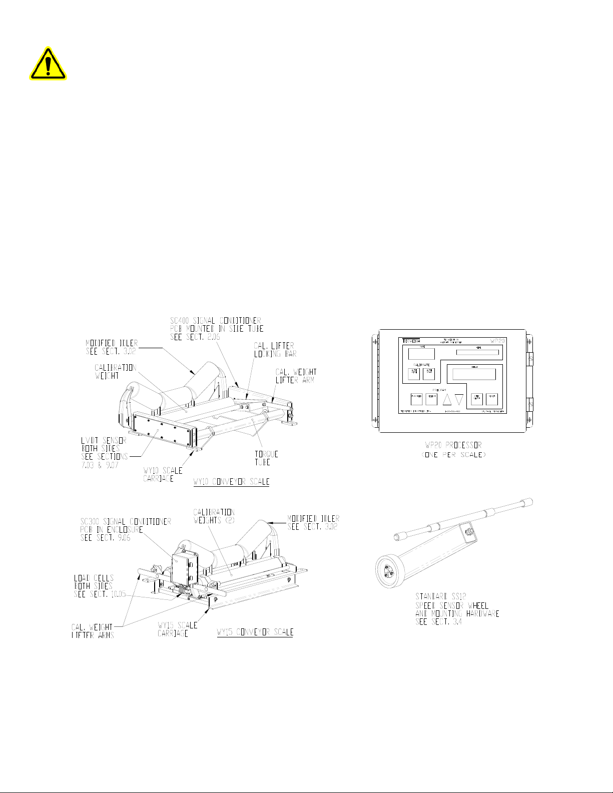
main components of the scale system are the scale carriage, the Tecweigh 20 Weight Processor
(WP20), speed sensor, signal conditioner (SC), load cells or LVDT sensors, calibration weights
with lifter arm(s), and the weigh idler.
The scale carriage mounts on the conveyor stringers and uses one or two of the conveyor’s
existing idlers depending on which Tecweigh scale model was purchased. Models WY10 and
WY15 replaces one idler while the WY20 and WY25 replaces two idlers. The speed sensor
wheel rides on the return side of the belt to indicate the speed the belt is moving. Load cells or
LVDT sensors on the scale carriage measure the weight of material on the belt. The weight and
speed signals are sent to the signal conditioner mounted on the scale carriage. These signals are
electronically conditioned and then transmitted to the WP20 Weight Processor via RS485 serial
communications. This conditioning function also allows the FC20 to be mounted remotely from
the scale when necessary. The WP20 does all RATE, TOTAL, and belt speed calculations for
display. It can also send that and additional information to remote devices.

- 8 -
2.04 Conveyor Scales (WY10/WY10HD/WY15/WY20/WY25)
ATecweigh conveyor scale typically consists of a carriage, load cell(s) (or LVDT(s)) for
sensing weight, a belt speed sensor, a signal conditioner, and a weight processor (FC20 or
WP20). Most are also equipped with self storing calibration weight(s) and a mechanism for easy
manipulation. Additional scale information is provided in chapter 3.
2.05 Modular Conveyor Scales (HY15 & HY25)
A Tecweigh modular conveyor scale typically consists of a left and right module including load
cell, a tail pulley speed sensor, a signal conditioner enclosure, and a weight processor (WP20,
FC20, or WPLD). Specific modular scale information is provided in section 3.03.
2.06 Weigh Belt Feeders (WF10/WF14/WF16/WF18)
A Tecweigh weigh belt feeder (WBF) is a complete weighing and conveying mechanism that
consists of the head and tail pulleys, a drive motor, a belt tensioner, a belt speed sensor, the belt,
one or more weighing idlers, and the material weight sensing load cells or LVDTs. A Tecweigh
WBF is also normally equipped with a self storing calibration weight(s) and a mechanism for
easy operation.
2.07 Signal Conditioner (SC)
Material weight and belt speed signals are sent to the signal conditioner (SC) which is normally
mounted on the scale carriage. The signal conditioner has two functions: first, it collects and
electronically conditions the material weight and belt speed signals; and, secondly, it detects
problems at the scale such as faulty weight or speed sensors. The weight, speed, and scale status
information is continuously sent to the WP20 via the standard RS485 serial communications
protocol.
2.08 Tecweigh 20 (WP20)
The WP20 is the microprocessor of the scale system. All settings are stored in the WP20 such as
belt length, calibration weight, and desired I/O options. At the very basic level, it receives belt
speed and material load data from the SC and displays the corresponding material RATE on the
WP20’s display. The WP20 accumulates a TOTAL of material weight that passes over the scale.
While displaying the RATE and TOTAL, the WP20 also interprets status information from the
SC and displays status messages when appropriate.
However, the WP20 can do much more than just display RATE, belt SPEED, TOTAL, and scale
status. Various analog, relay, and serial inputs and outputs, allows control of the WP20's primary
functions remotely using a PLC or other plant controller. Furthermore, up to sixteen WP20s can
be daisy chained on one RS485 serial bus for full plant automation.
In addition, optional fieldbus communication cards are available for the WP20 processor. They
are add on plug-in interface devices that allows the user to remotely initiate actions (like AUTO
ZERO) and retrieve data (like RATE and TOTAL) using one of the five available protocols:
Remote I/O, Profibus, Modbus RTU, Ethernet, and Device Net.

- 9 -
2.09 I/O Quick Reference Guide

- 10 -
3.01 Proper Installation, WY & HY Belt Scale Models
Proper scale installation is critical for high accuracy and repeatability. A properly mounted scale
should be located on a rigid, horizontal conveyor. If the conveyor is at an incline, assure it is not
so steep that material rolls back on itself causing it to be weighed twice. The belt and idlers
should move smoothly and the scale should be mounted in an area free of extreme temperature,
wind and vibration. The shimming and aligning of the idlers surrounding the scale is extremely
critical, because the weigh area must be slightly raised above the other idlers as indicated below.
Avoid the following!
•Badly worn belts and splices
•Joined belts with different thickness
•Poor belt training or alignment
•Wind, temperature, or vibration extremes
•Material build-up on belt, idlers or calibration weights
•Loosely mounted unstable conveyor
•Idlers with steep trough angles
•High belt tension
•Steep conveyors allowing material to roll back
•Belt skirting or other interference near scale
CHAPTER 3 – SCALE INSTALLATION

- 11 -
3.02 Idler Preparation, WY Models
After finding a suitable location for the scale, reduce the conveyor belt tension. Raise the belt so
it is supported at least one foot above the idler where the scale will be located and also one foot
above the three idlers before and after the scale. Note, if you are installing a dual-idler scale
(model WY20 or WY25), follow the same instructions as for the single-idler scale (model WY10
and WY15) and just repeat the instructions for both idlers. Short conveyors might only have two
idlers on one or both sides of the scale, but this is not recommended because accuracy might
suffer. If this should occur, consult the Tecweigh service department for advice (Section 2.01).
DO NOT WELD ON OR NEAR THE SCALE!!!
1) Mark the center of each roller on the scale idler, three idlers before the scale, and three after
(see below).
2) Remove the idler where the scale will be located--this will be used as the weigh idler.
3) Remove the weigh idler's factory mounting pads.
4) Center the weigh idler on the unpainted scale mounting pads and mark the location on idler.
5) Remove the idler and the unpainted mounting pads from scale.
6) Weld the unpainted mounting pads to the idler at the previously marked locations.
7) Weld a reinforcement gusset in each corner of the weigh idler.
8) Paint the weigh idler for corrosion prevention.
With the weigh idler modification complete, mount the idler on the scale using the four ½” bolts
provided. Center the idler on the scale as indicated below.
WY10 Scale Carriage WY15 Scale Carriage
- 12 -
3.03 Scale Mounting, WY Models
Place the scale carriage with the modified idler on the conveyor stringers. Center and align the
scale between the stringers and mark the location of the mounting holes. Alternatively, you can
use the dimension drawings in Section 10 for marking hole locations, but using the scale as a
template is preferred. Slide the scale out of the way and drill the four mounting holes. Place the
scale over the holes, but do not tighten the bolts yet.
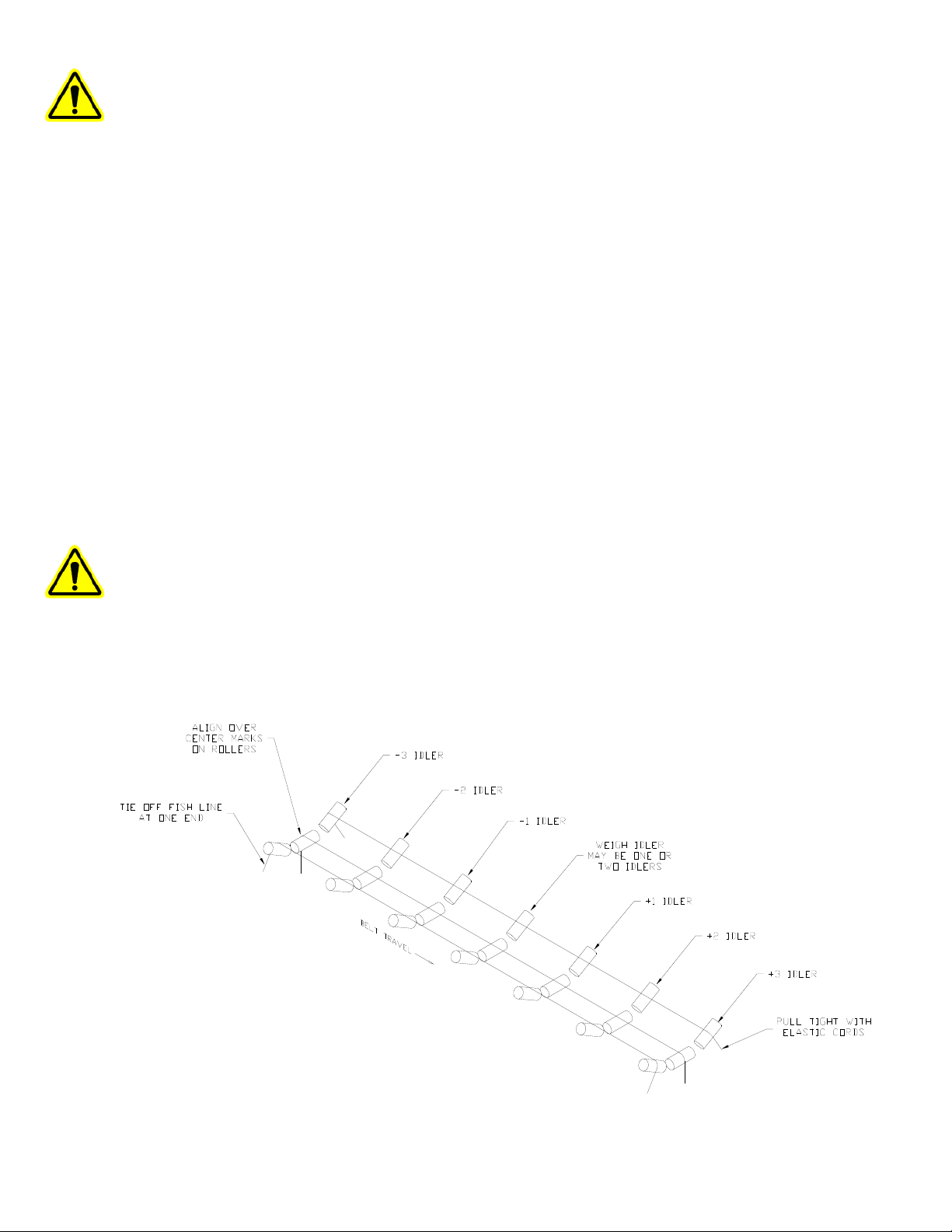
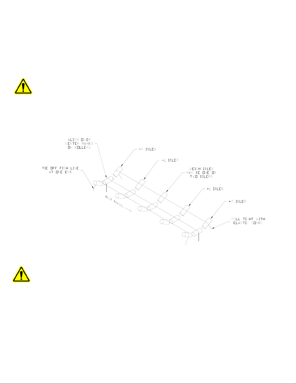
Now align the weigh idler with the three idlers on either side of the scale using the fish line and
shims provided. Perform the instructions following and refer to the diagram below.
1) Loosen the three idlers before and after the scale.
1) Shim the +3 and -3 idlers up 3/8 of an inch, center them on the stringer, and re-tighten the
bolts.
3) Stretch three fish lines across the idlers centered on the +/- 3 roller center marks.
4) Use elastic cords to hold the fish line in place at each end.
5) Lower the calibration weight on the scale so the idler is at its normal running height.
6) Shim the scale feet leaving a 1/16 inch gap between weigh idler and fish line.
7) Use thin shims under the scale, if necessary, so it does not rock or pivot while laying flat.
8) Tighten the scale carriage bolts.
9) Shim and tighten the +/- 1 and +/- 2 idlers with a 1/16 inch gap between the fish line and the
roller centers.
The idler alignment is very important! Before proceeding, verify that the fish line is exactly
over the center marks on the rollers and there is exactly a 1/16 inch gap between all the rollers
and fish line. Also verify that the idlers are exactly square with the stringers.
Remove 1/8 inches (leave 1/4 inch) of shim from the +/- 3 idlers and tighten them down. Re-
tension and align the belt so that it tracks in the center of the idlers. Make sure all of the rollers
are turning freely and are securely bolted down.
- 13 -
IMPORTANT!!! On the WY15 and WY20 scale models, remove the two safety plates on both
ends of the idler mounting bar. These plates prevent overloading of the load cells during
shipment. When using a portable conveyor, use the safety plates during transportation. Refer to
the diagram in section 9.06.
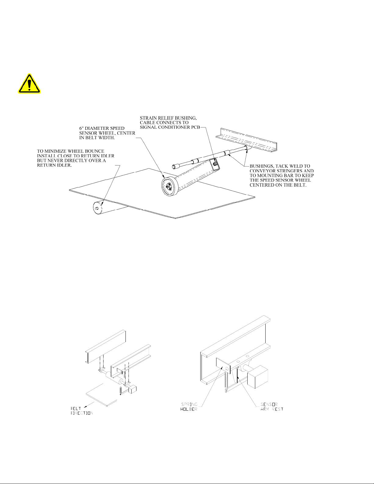
3.04 Speed Sensor Installation, WY Models
The standard SS12 speed sensors:
Mount the speed sensor assembly so that it is aligned exactly with the belt. If it is not straight, it
might bounce and wear down the wheel or belt. Position the wheel so that it is at least 6 to 12
inches from a return idler.
1) Weld two of the supplied pieces of pipe to the conveyor stringers.
2) Slide the spacers (other pieces of pipe) and speed sensor assembly onto the pivot arm.
3) Tack weld the spacers so the speed sensor is loosely constrained, but can still swing freely.
The heavy duty SS11 speed sensor:
Since most brands and styles of conveyors are constructed differently, it’s not possible to give
specific installation instructions for the SS11 heavy duty speed sensor. However, four holes will
need to be drilled for the bearing bolt holes. Also, one bracket will need to be formed and
welded, on which to clip the spring, and a second bracket to hold the speed sensor arm
horizontal.

- 14 -
3.05 Modular Scale Description, HY Models
The HY15 is different from our other scales in that it a modular design. It does not have a single
rigid frame that an idler can be mounted on before scale installation. Instead it is a left and right
hand module that needs to be mounted on the conveyor structure and then the idler is mounted
between the modules. An HY15 is supplied with the components shown below.
An HY15 scale can be mounted in series creating a dual idler scale, an HY25. An HY25 would
include a second scale that would be identical to the first, but with out the signal conditioner
enclosure. See XXX for mechanical drawings of the HY15 and HY25.
3.06 Idler Preparation, HY Models
After finding a suitable location for the scale, reduce the conveyor belt tension. Raise the belt so
it is supported at least one foot above the idler where the scale will be located and also one foot
above the two idlers before and after the scale. Note, if you are installing a dual-idler scale
(model HY25), follow the same instructions as for the single-idler scale (model HY15) and just
repeat the instructions for both idlers.
DO NOT WELD ON OR NEAR THE SCALE!!!
1) Mark the center of each roller on the scale idler, two idlers before the scale, and two after (see
below).
2) Remove the idler where the scale will be located--this will be used as the weigh idler.
3) Weld a reinforcement gusset in each corner of the weigh idler.
4) Remove the weigh idler's factory mounting pads.
5) Paint the weigh idler for corrosion prevention.

- 15 -
3.07 Scale Mounting, HY Models
The HY design utilized a asymmetric design in that the left and right mounts are slightly
different. One side incorporates a rigid mount that bolts directly to the load cell. The other side
uses a spherical rod end bearing to allow some flex in the mounting structure while minimizing
drift and inaccuracies associated weak or flexing structures.
Although this benefit can be great in many applications it is not always the appropriate mount to
be used. The following list highlights applications that won’t benefit from the spherical bearing
mount, and the symmetrical rigid mount that is also supplied should be used.
The spherical bearing mount may be detrimental in these application
•Applications with over 150lbs per foot of belt load. (500Kg per meter)
•Non-top mounted CEMA idlers.
•Flat carrier idlers or rollers.
•Belt speeds over 600 FPM.
•Belt widths over 48” (1200mm).
Consult our factory for unique applications. The HY15 modular scale is very adaptable.
If the application requires a symmetrical rigid mount simply remove the shoulder bolt from the
rod end bearing to disassemble. Then use the two bolts supplied with the rigid mount to attach it
to the end of the load cell. See below.
Because the HY modular scale is in two separate assemblies they need to be mounted parallel
and square with each other. On a standard top mounted CEMA idler conveyor the left and right
modules should bolt directly into the same mounting holes of the weighing idler.
- 16 -
Mount the modules directly across from each other using a square or common reference point.
The mounts should also be centered between the closest idlers on either side of the weighing
idler(s). Once centered and squared tighten down the mounting bolts for the left and right
modules.
You can now place the modified idler on top of the mounting pads. Make sure the belt direction
of the idler is correct. Assemble the idler hold down clamps with the carriage bolts and hardware
supplied. Only finger tighten at this point. Loosen the mounting bolts on the end of the load
cells with the rigid mount on them. Just enough to allow the mounting pad to settle and come
into full contact with the inverted angle of the CEMA idler.
For HY25 dual idler installations repeat this process for the second idler.
Note that if the structure is truly flat and square the idler(s) that have now been mounted on the
modular scale assemblies is approximately 1/8” higher than the adjacent idlers. This is not
always the case but the following instructions are based on this assumption. Adjustments and
shim size references may need to be different in your specific application.
Now align the weigh idler with the three idlers on either side of the scale using the fish line and
shims provided. Perform the instructions following and refer to the diagram below.
1) Loosen the two idlers before and after the scale.
2) Shim the +2 and -2 idlers up 3/16 of an inch, center them on the stringer, and re-tighten the
bolts.
3) Stretch three fish lines across the idlers centered on the +/- 2 roller center marks.
- 17 -
4) Use elastic cords and/or weight to hold the fish line in place.
5) Measure with a shim the distance between the weigh idler and the fish line on the weigh
idlers. It should be 1/16 inch gap between weigh idler and fish line.
6) If modification to the weighing idler height to attain 1/16” gap is necessary now would be the
time to shim the HY15 modules or change the 3/16 shim on the +2 and -2 idlers.
7) Shim and tighten the +/- 1 idlers with a 1/16 inch gap between the fish line and the roller
centers.
8) Drop the +2 and -2 idlers approximately 1/8” by removing shims.
The idler alignment is very important! Before proceeding, verify that the fish line is exactly
over the center marks on the rollers and there is exactly a 1/16 inch gap between the fish line and
the weighing idler(s) and adjacent idlers. Also verify that the idlers are exactly square with the
stringers.
Remove 1/8 inches (leave 1/4 inch) of shim from the +/- 2 idlers and tighten them down. Re-
tension and align the belt so that it tracks in the center of the idlers. Make sure all of the rollers
are turning freely and are securely bolted down.
3.08 Speed Sensor Installation, HY Models
The HY15 and HY25 standard RL200 speed sensor:
Since most brands and styles of conveyors are shaped differently it is difficult to give specific
installation instructions for the speed sensor. As indicated diagram below, you will need to drill
a hole in the tail pulley shaft and insert a smaller shaft stub that the speed sensor will couple to.
You will also need to form two brackets that are required to hold the speed sensor in place. The
rotation of the tail pulley is critical for correct orientation of the speed sensor. The speed sensor
should rotate in a way that it pushes against the sensor arm rest NOT pull on the spring.
1) Drill a 3/8" diameter hole exactly in the center of the tail pulley or any live shaft 1/2" deep.
2) Insert shaft stub and weld in place. Stub should protrude about 1" from the shaft face.
3) Hold the speed sensor up to the shaft to form an arm rest and spring holder.

- 18 -
4) Place the arm rest and spring holder in a suitable location and weld to the stringer.
5) Tighten the coupling onto the shaft stub.
6) Slide speed sensor shaft into the coupling and tighten.
7) Attach spring to speed sensor arm and spring holder.
8) Run conveyor. Speed sensor should have minimal amount of wobble.
9) Run required length of electrical cable to scale.
See Section 3.04 for other speed sensor options that might be included with the HY15 or HY25
scale.
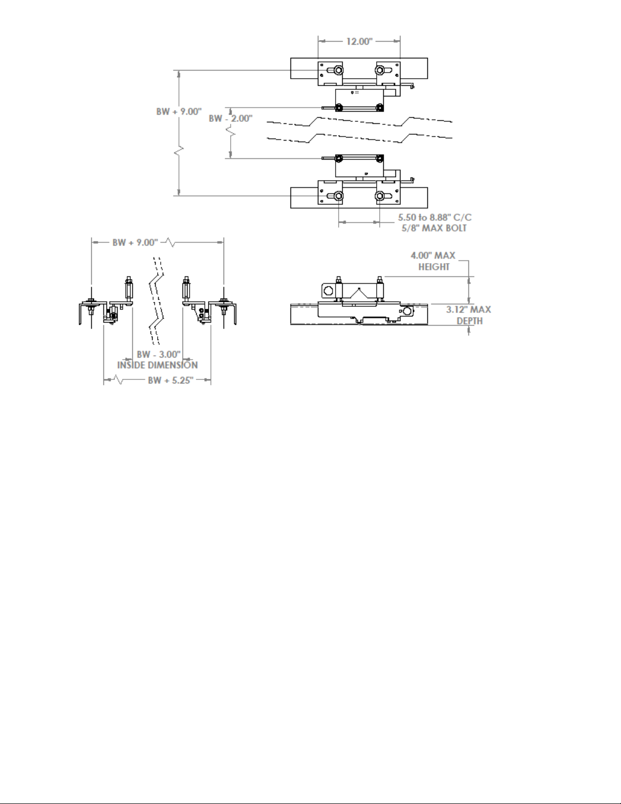
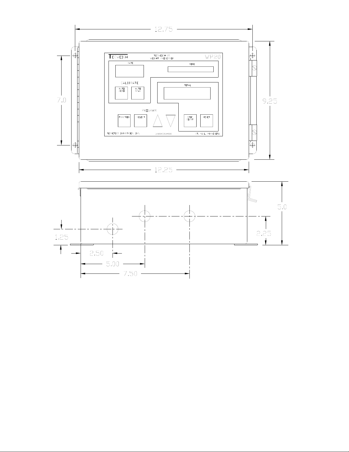
3.09 Tecweigh 20 (WP20) Installation
Mount the WP20 in a reasonably clean area away from severe heat and isolated from vibration.
Avoid areas of bright sunlight since the lighted displays may become difficult to read. Where
outdoor installation is necessary, the WP20 should be mounted under a “roof” or “dog house” to
provide rain and snow protection as well as shade. Be sure to allow room for the enclosure door
to swing out. The WP20 can be located up to 4000 feet from the scale. For longer distances,
however, one person will be required at the processor and one person at the scale (to lower the
calibration weight when required and/or when calibrating the LVDT’s). Refer to the mounting
dimensions in the figure below. Refer to Section 4.1 for WP20 wiring diagrams and information.
- 19 -
This manual suits for next models
10
Table of contents


