TECNICCAT MAMNET ECO 20 User manual
MANUAL
MAMNET ECO 15 / 20 / 30 / 45

1
Dear Customer,
Thank you for choosing a MAMNET ECO SALT ELECTROLYSIS system for your swim-
ming pool.
MAMNET ECO SALT ELECTROLYSIS SYSTEMS have been designed and manufac-
tured for the specific requirements of the water in your swimming pool. Its simple manage-
ment, easy installation and low maintenance ensure that you will almost never have to
worry about it.
Before beginning installation, read carefully this instructions manual and once the system
has been started, keep it in a safe place for future reference.
The instructions in this manual describe the operation of the models Mamnet Eco 15,
Mamnet Eco 20, Mamnet Eco 30, Mamnet Eco 45,ORP and pH.
CHECK elements supplied:
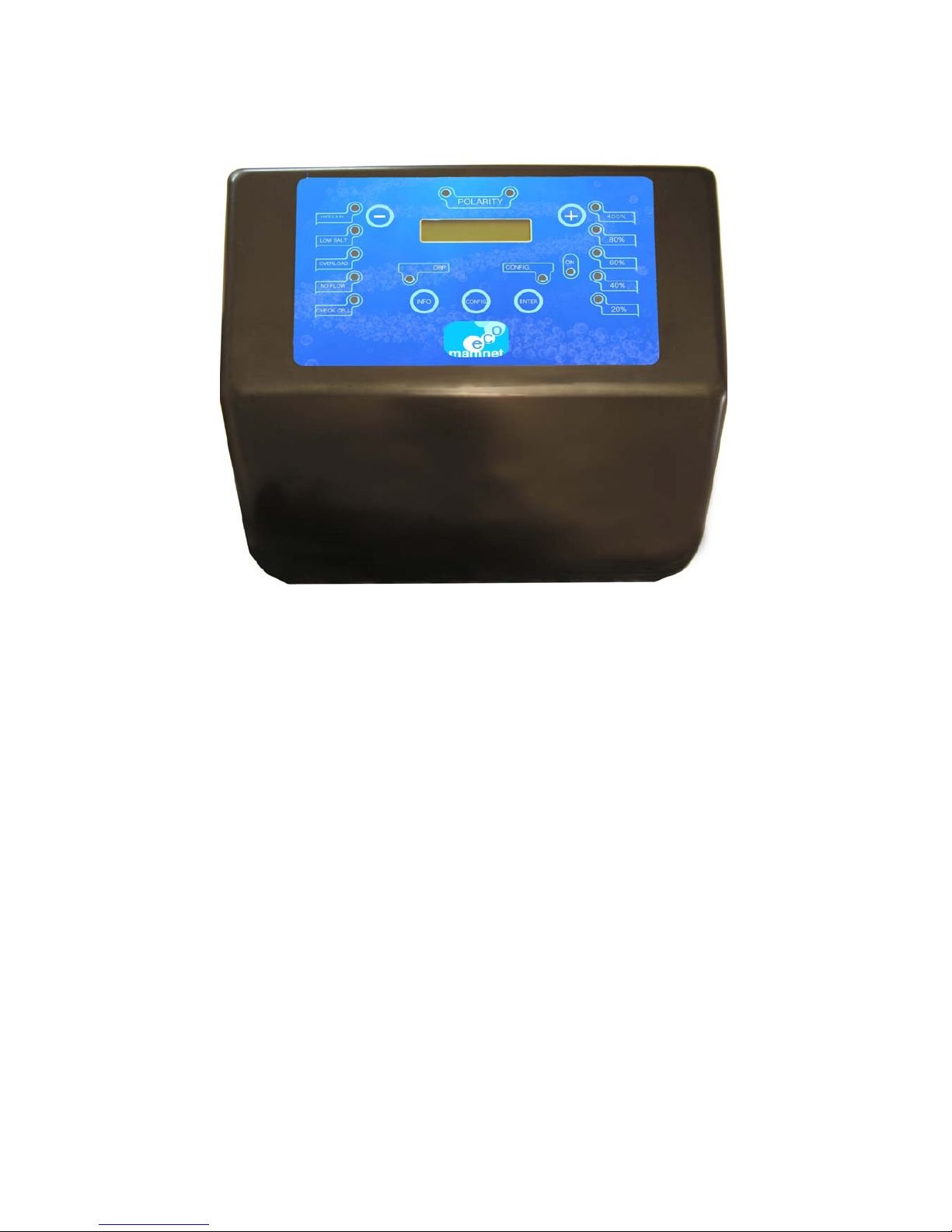
Central Processing Unit (CPU)
Electrode
Electrode holder
Manual
Optional ORP:
1 ORP Probe.
1 Probe holder.
1 Buffer solution 465mV
Optional pH:
1 pH Probe
1 Probe holder
1 Peristaltic pump
1 Buffer solution pH4
1 Buffer solution pH7

2
VERY IMPORTANT
Before installation or carrying out any maintenance task, disconnect the power cable from the
CPU (230 Vac).
The system must be installed by qualified people, in accordance with all local and national
electrical regulations.
Check that the power supply voltage corresponds to which is indicated on the label located on
the side.
Be sure the electrical connections are firm in order to avoid false contacts, resulting in
over-heating.
Do not connect the network power supply cable before having made all power supply
connections to the electrolysis cell.
Choose an installation site where the system will be easy to access and enable easy viewing
of the CPU and the electrode.
TECHNICAL SPECIFICATIONS:
DIMENSIONS:
CPU SPECIFICATIONS:
CONTROL MICROPROCESSOR
POWER SUPPLY 230 V ac/50-60Hz/H50RR-F-3G (3 x 1 mm2)
OUTPUT 7,5V dc, 15A (MamNet Eco 15) / 6,8V dc 20A (MamNet
Eco 20) / 6,3V dc 30A (MamNet Eco30) / 7V dc 45A
(Mamnet Eco 45) max.
RV-K-1000V 2x6mm² cable electrodo
CABLE FOR TEMPERATURE +
WATER DETECTOR
3x1 mm2H05VV-F-3G1
SELF-CLEANING AUTOMATIC PROGRAMMABLE POLARITY CHANGE
FUSIBLE 2A (MAMNET ECO 15, 20) / 3,15A (MAMNET ECO30, 45)
REFRIGERATION CONVECTION/FORCED

3
ELECTRODE SPECIFICATIONS:
HOW TO INSTALL: Recommended installation diagram:
RECOMMENDED SALINITY 4.5 gr NACI / Litre
SALINITY RANGE 4-6 gr/L
ELECTRODE TITANIUM WITH SPECIAL OXIDES
MAXIMUM PRESSURE 1,5 kg/cm2
ELECTRODE HOLDER POLYMER FROM THE METHACRYLATE
FAMILY
CONNECTION TO PIPEWORK GLUED WITH PVC ADHESIVE / Æ 63
NaCIO PRODUCTION (25ºC 4,5 gr/L NaCl) 15g/h 360gr/day
20gr/h 480gr/day,
30g/h 720gr/day
45g//h 1080gr/day
MINIMUM FLOW RECOMMENDED 7,53/mh ECO15, 11,53/mh ECO20,
163/mh ECO30, 203/mh ECO45
No OF PLATES PER ELECTRODE 10+ MAMNET ECO 45 FLOW DETECTOR
6+ MAMNET ECO 30 FLOW DETECTOR
4+MAMNET ECO 20 FLOW DETECTOR
4 SHORT + MAMNET 15 FLOW DETECTOR
TEMPERATURE DETECTOR SEMI-CONDUCTOR
LOAD LOSS
0,15 Kgr/cm2 < 20 m3/h
CPU ABOVE THE ELECTRODE
PUMP pH
PROBE ORP
INJECTOR pH
PROBE pH
SWITCH FLOW
STOP2

4
Always install the MAMNET ECO system CPU vertically and on a rigid surface (wall).
To guarantee a good state of conservation, the equipment must always be stored in a dry and
well-ventilated place. Given the level of water-tightness of the MAMNET system's CPU,
do not install during bad weather.
The CPU must be installed sufficiently far away from the electrode holder so that it is not
subject to accidental water splashes. It must also be installed above the CPU.
Be especially careful to avoid corrosive environments due to minimised pH
solutions (particularly those made with hydrochloric acid "HCI", also known
commercially as "muriatic acid" or "spiritsof salt").
It is recommended to use minimised pH (pH minus) based on diluted sulphur to avoid
corrosive environments in the technical area.
The CPUs “STOP2” contact must be connected to a potential-free contact in the in
the purifier's control panel, so that the pump and the MAMNET system are
connected simultaneously. If the pump stops for any reason, the CPU will also
stop.
ELECTRODE HOLDER:
The electrode holder is made of a transparent polymer which contains the electrode.
Ensure the electrode holder is in a place that is protected from bad weather and always
behind the filtration system. If there are other devices in the facility such as heat pumps, con-
trol systems, etc., these must always be put into place before the electrolysis system.
The installation must allow the user to easily access the electrode.
The electrode holder must always be placed HORIZONTALLY in a place in the pipes so that it
is separate from the rest of the installation by two valves. This ensures maintenance tasks can
be carried out with no need to totally or partially empty the swimming pool.
CPU:
5
If the electrode holder is installed in bypass (recommended option) insert a valve that
regulates the flow.
The following notesmustbe taken intoconsideration beforedefinitivelyinstalling the system:
Flow direction must be respected (input / output).
The re-circulation system must guarantee the minimum flow indicated in the technical
SPECIFICATIONS TABLE for each model.
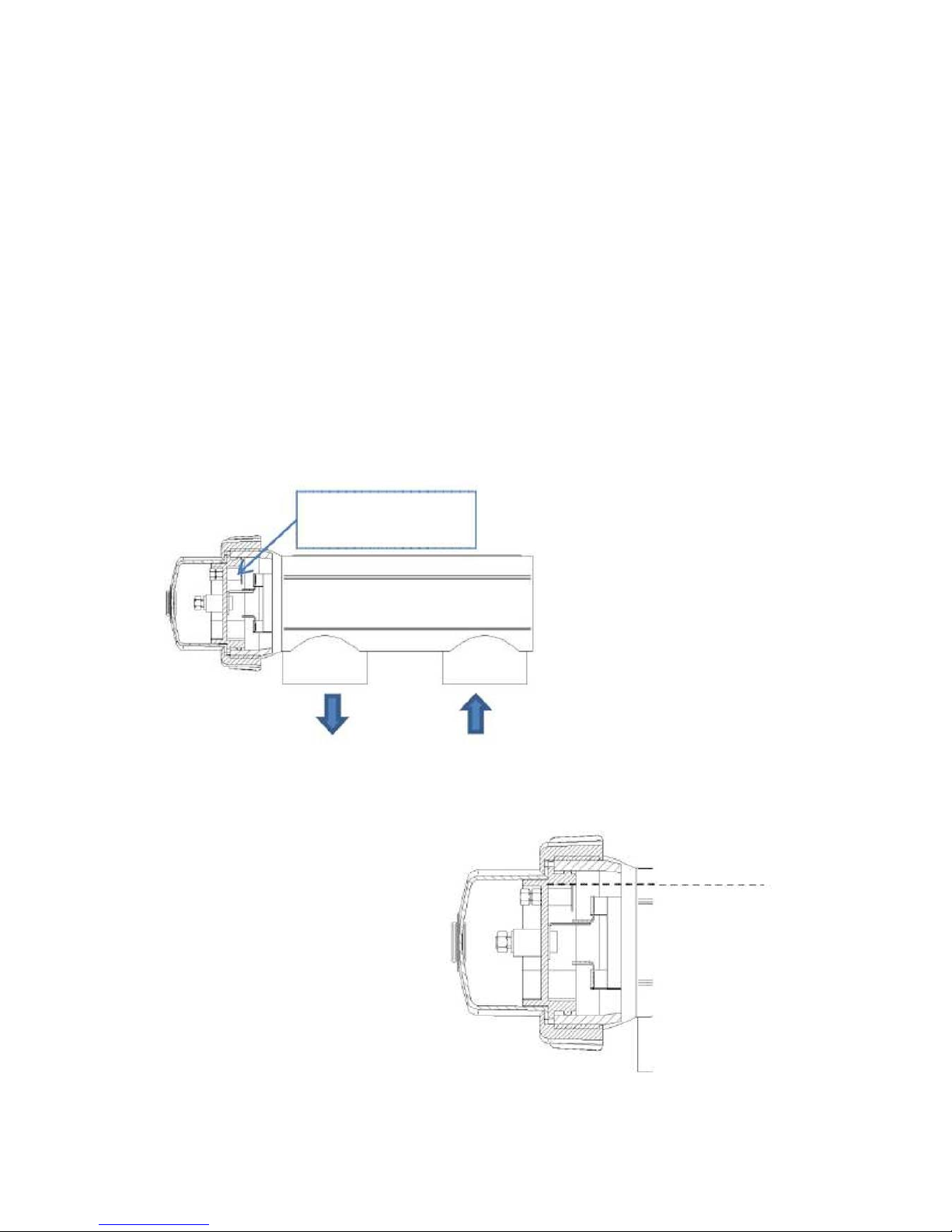
The float detector system is activated if there is no re-circulation (water flow through the cell,
or if that one is very low). If the electrolysis gas is not evacuated, a pouch will be
generated that electronically isolates it from the auxiliary electrode. Thus, when the
electrode is inserted into the electrode holder, the level probe (auxiliary electrode) must
be located on the upper part of the electrode older. The safest arrangement is
indicated in the recommended installation diagram (page 3).
Auxiliary electrode.
(Flow detection)
Output Input
Water level

6
METHODS FOR INSTALLING THE ELECTRODE HOLDER:
Other arrangements are only acceptable if they also enable low flow to be detected. Installations
according to the “not acceptable” configuration must be avoided, since it will not be possible
to detect "No Flow" or a large gas bubble may form.
CORRECT:
NOT ACCEPTABLE:
WARNING:
If the input and output valves to the pipe
where the electrode holder is installed are
closed simultaneously, the flow detector
will not work correctly, with a risk of
rupture resulting. Although it is an
extremely unusual situation that can be
avoided by blocking, once the
equipment is installed, the return valve
to the swimming pool, so that it cannot
be manipulated accidentally.
7
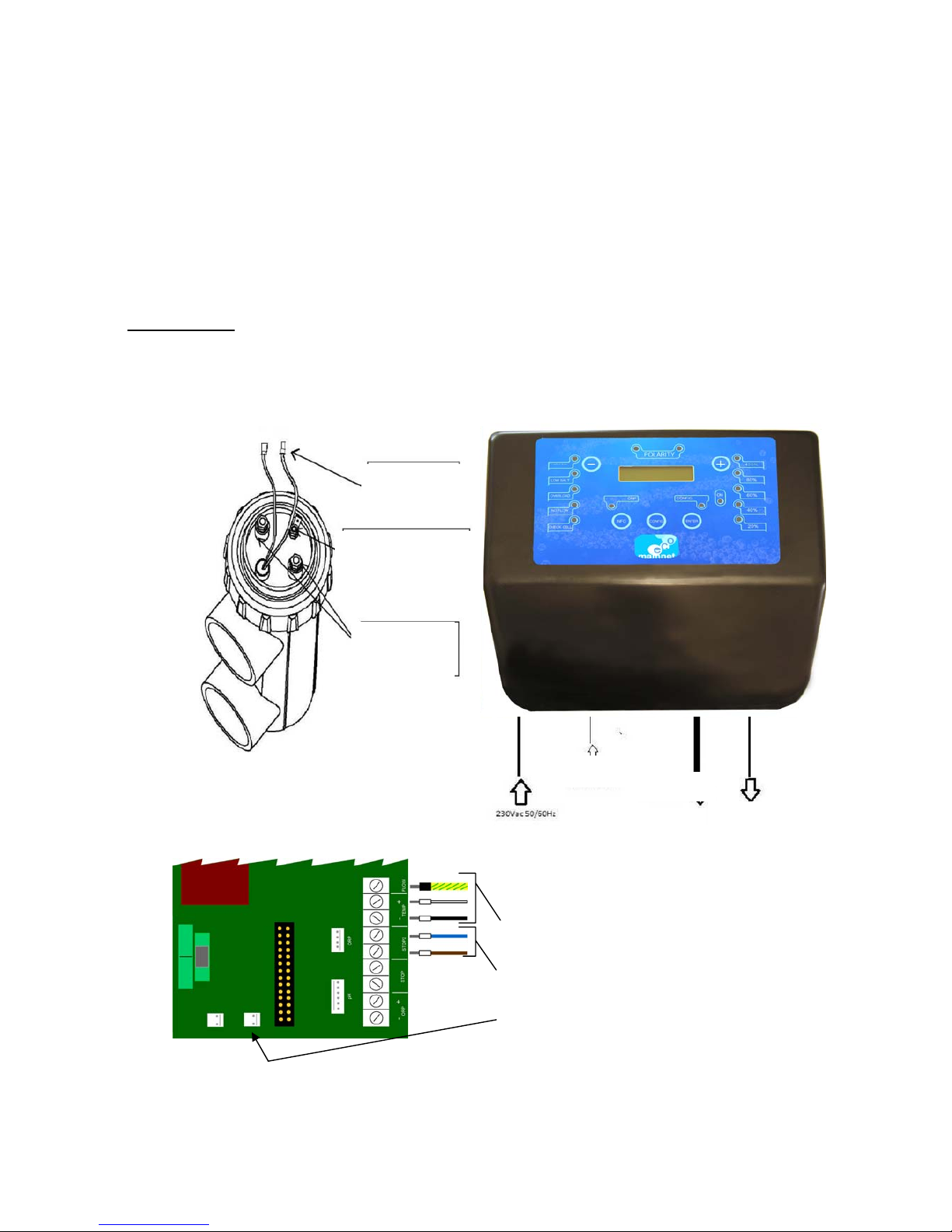
ELECTRICAL CONNECTION:
Check that all connections are firm in order to avoid false contacts, which results in over-heating.
Connect the electrode and the CPU according to the diagram on this page.
The system changes the electrodes' polarity automatically, depending on the
programming, resulting in the self-cleaning effect (anodic calcification). When
"Contact 1" is cathode "Contact 2" is anode and vice versa.
IMPORTANT: Due to the relatively high continual current intensity that circulates the electrode
power supply cables, their lengths and sections must not be modified without first consulting the
authorised distributor.
The CPU - ELECTRODE, connection cable must be from the recommended section in this
manual.
Temperature
probe
Auxiliary
electrode
Electrode
contacts
ON/OFF ELECTRODE
FLOW DETECTOR
RELAY PLATE:
Electrode cables
Contact free power (pág.16)
In MAMNET 45 connect here the fan
8
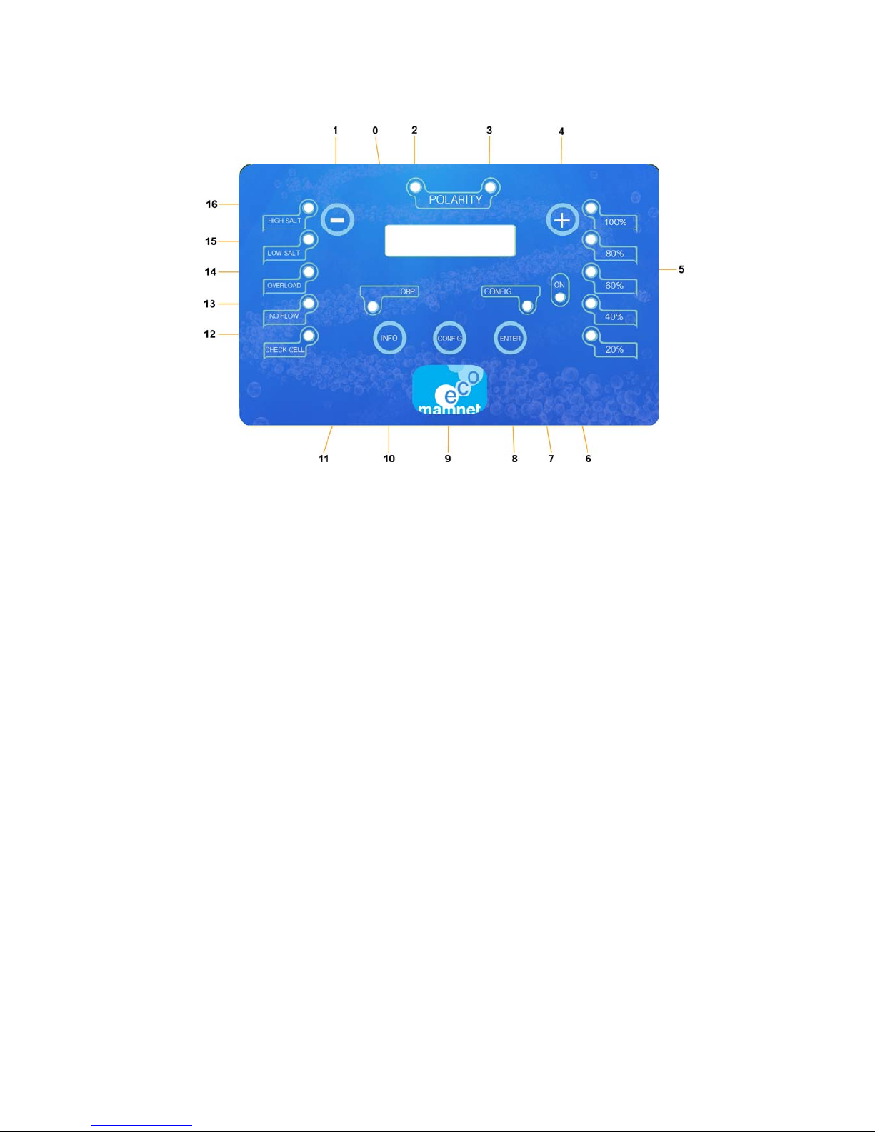
MAMNET ECO FUNCTIONS:
1.
Button to reduce chlorine production and move
around the menu.
2.
LED that indicates the equipment is operat-
ing in
direct current.
3
. LED that indicates the equipment is operat-
ing in reverse current.
4
. Button to reduce chlorine production and move
around the menu.
5
. LEDs to indicate the approx. power being used by
the CPU.
6
. LED to indicate there is voltage.
7
. LED to indicate the equipment is in configu-
ration mode.
8
. Button to execute commands and move
around the menu.
9.
Button to configure the system and move
around the menu.
10.
Button
for MAMNET ECO information and to
move around the menu.
11. LED to indicate whether the ORP function is
connected or not.
12. LEDto indicate thattheelectrode needs to
be checked.
13. LED to indicate lack of water in the
electrode holder.
14. LED to indicate an over-consumption in the
MAMNET system.
15. LED to indicate a low salt level.
16. LED to indicate a high salt level.
0.
SCREEN THAT SHOWS THE INDICATIONS AS WELL AS FAULTS AND STATUS

9
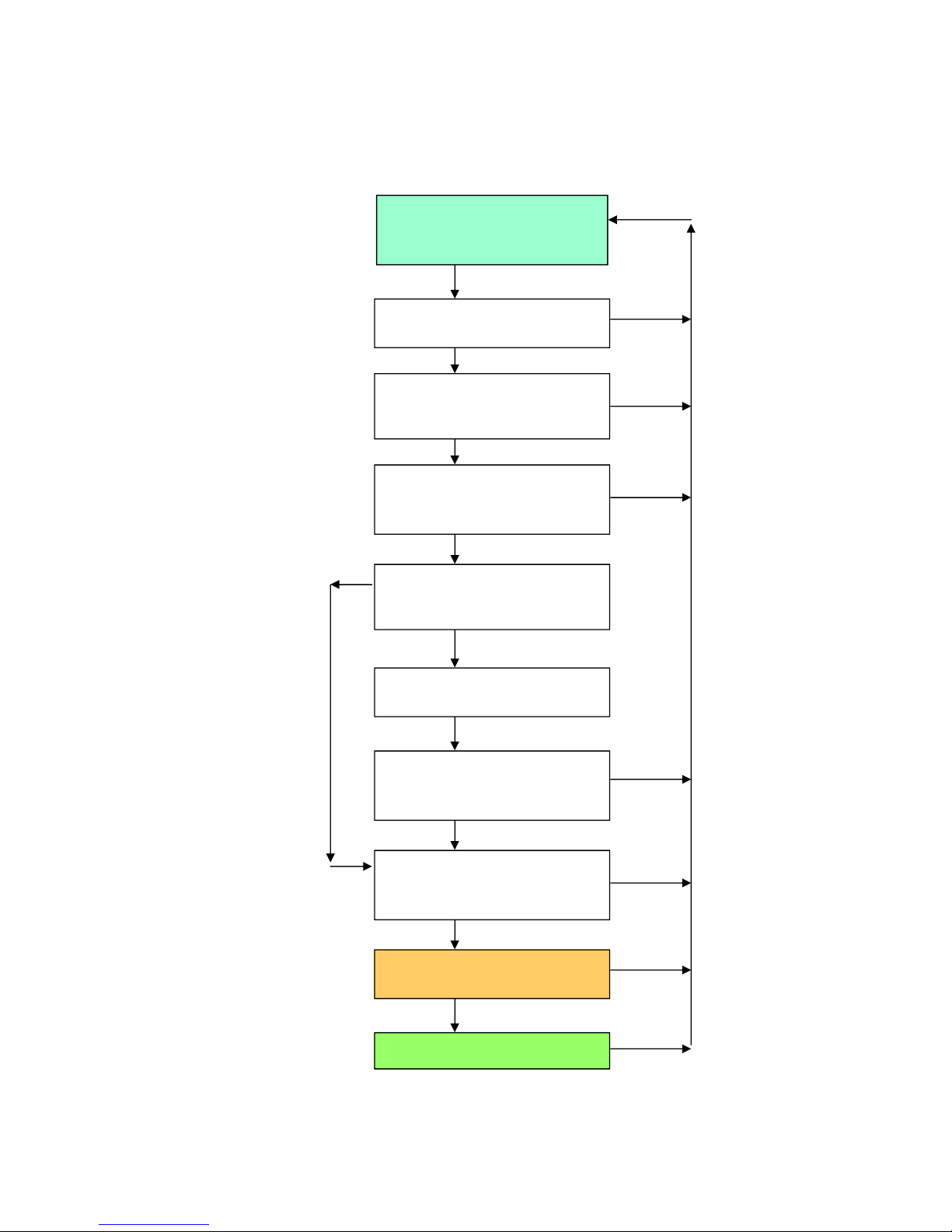
MENU CONFIGURATION:
The screen usually shows the production programmed on the upper line and the system status
on the lower line. There are two menus; the INFO information menu and the CONFIG
configuration menu.
LANGUAGE screen: Pressing CONFIG shows the language selected at this time. The
language can be changed using the +/- buttons and searching for another: (English, Spanish,
Catalonian, French, Flanders, Italian and Russian*). Whether the language is changed or
not, pressing CONFIG passes to the next screen and pressing ENTER returns to the start
screen.
ORP screen: Shows the current selection. The +/- buttons are used to change the current
option (- = No) (+=Yes). If “No” is selected, the pH screen will appear. If the option is
YES, by + / - we can choose how we want it to work: 4-20mA, 0-10V, NC contact, NO
contact, FIX or ORP (for ORP see page 24). Once selected, by pressing CONFIG we
then pass to the next screen and by pressing ENTER we return to the home screen.
Screen pH: If we choose "NO" then the screen goes to the CLEANING HOURS. If the
option is YES we then open the pH menu (see page 26).
CLEANING HOURS screen: Shows the current selection, if the selection is changed by
pressing CONFIG, the SEAWATER screen will appear. Use the +/- buttons to change
the current option (no cleaning or every 3h, 4h up to 8h). The hours selected are those that
will change the polarity. The higher the calcium content in the water, the less time will
pass between changes in polarity!Once the time has been selected by pressing CONFIG,
the next screen will appear and pressing ENTER will return to the start screen.
SEA WATER screen: Shows the current selection. If the selection is not changed, pressing
CONFIG will go to the ELECTRODE HOURS USE screen. Use the +/- buttons to change
the current option (Yes / No). Press ENTER to return to the start screen.
ELECTRODE HOURS USE screen: shows the total and partial hours of operation: Pressing
CONFIG goes to the next screen SET TO ZERO and pressing ENTER returns to the start
screen.
SET TO ZERO screen: Use the + / - buttons to set the partial hours counter to zero. The total will
not change. When the CHECK CELL LED is illuminated, requesting to check the electrode ,
and once it has been checked, go to this screen and set the partial to zero, which will turn off the
LED. If do not set to zero (No -) is selected, the system will return to the start menu. If yes
(Yes +) is selected, the set to zero screen will be displayed and the system will return to the
start screen.
H HOW TO MOVE AROUND THE MENUS:

10
CONFIG
PROG. PRODUCTION
PRODUCCION PROG.
<state / estado>
LENGUAGE / IDIOMA
SET TO ZERO / PONER A CERO
pH INCREASE
SUBIR pH
- NO + YES
SEA WATER / AGUA DE
MAR
PH CONTROL
<current>
CONTROL PH <actual>
ORP <current / actual>
CELL USE HOURS
HORAS USO CELULA
config
config
config ( - No)
config ( - No)
config
config
config
+ yes
CELL USE HOURS SET TO ZERO
HORAS USO CELULA PUESTAS A
CERO
enter
enter
enter
enter
enter
enter LENGUAGE / IDIOMA
+ - + -
config
ORP YES / SI
TYPE: 4/20 mA
+ Yes ORP YES / SI
TYPE: 0/10V
ORP YES / SI
TYPE: FIX
ORP YES / SI
TYPE: N C
ORP YES / SI
TYPE: N O
ORP YES / SI
TYPE: ORP
+ -
+ -
+ -
+ -
+ -
CLEANING HOURS
HORAS DE LIMPIEZA
<new value/ nuevo valor>
+ -
+ -
config
SEA WATER / AGUA DE
MAR + -
+ -
config
FIX PRODUCTION
PRODUCCIÓ FIJA
<x> G/H
config
config
SET POINT
HISTERESIS
PROBE CALIBRATION
CALIBRACION SONDA
- NO +YES
SETTING PROBE
config
+ YES
config ( +Yes)
CALIBRATE
PROBE?
CALIBRAR SONDA?
CHANGE PH PA-
RAMS?
PROGRAMAR PH?
HIGH TARGET
PH MAXIMO
X.XX
LOW TARGET
PH MINIMO
X.XX
+ Yes
PUMP RUN TIME
SEGUNDOS BOMBEO
XX SEG
PUMP STOP TIME
SEGUNDOS PARADA
XX SEG
Config (-No)
+ Yes
PH REFERENCE 1
REFERENCIA PH 1
X.XX
PUT PROBE IN REFEREN-
CE SOLUT
INTRODUCIR SONDA EN
REFERENCIA
SAMPLING
MUESTRANDO
X.X (YYY)
PH REFERENCE 2
REFERENCIA PH 2
X.XX
PUT PROBE IN REFEREN-
CE SOLUT
INTRODUCIR SONDA EN
REFERENCIA
SAMPLING
MUESTRANDO
X.X (YYY)
OPCIONAL FUNCTION WITH PROBE ADAPTADOR ORP
INICIAL STATE
ADICIONAL FUNCTION WITH PROBE ADAPTADOR PH
PUMP FILL?
CEBAR BOMBA?
- NO + YES
-NO
+ ON - OFF
+ Yes
+ -
ALARM HIGH pH
ALARMA pH ALTO
XXX
ALARM LOW pH
ALARMA pH BAJO
XXX
ALARM HIGH ORP
ALARMA ORP ALTO
XXX
ALARM LOW ORP
ALARMA ORP BAJO
XXX
CLEANING HOURS
HORAS DE LIMPIEZA
X
config + -
enter
- NO

11
MENU INFORMATION:
Starting from the first screen, which indicates the status and the programmed
production.
Pressing INFO shows the screen with the actual production in gr/h and the %of power
used by the CPU. Pressing ENTER returns to the start screen.
Pressing INFO shows the screen with the water temperature in the electrode holder in
ºC and ºF. Pressing ENTER returns to the start screen.
Pressing INFO shows the screen with the salt concentration in the water in gr/L and ppm
from the last test made. Pressing ENTER returns to the start screen.
Pressing INFO shows the screen where a new test can be made and (Yes+/No-)
can be used to select:
⇒Selecting “NO” returns to the OPERATING HOURS screen.
⇒Selecting “YES” starts a new test and after a few seconds, the screen with
the current reading will appear. Pressing ENTER returns to the start screen.
Press INFO to return to the OPERATING HOURS screen.
If the ORP is activated, pressing INFO the screen shows the current ORP information.
Pressing ENTER it returns to the main screen.
Pressing INFO screen shows the current pH information if we have it activated.
Pressing ENTER returns to the start screen.
12
INFO
PROG. PRODUCTION
PRODUCCION PROG.
<state / estado>
REAL PRODUCTION, POWER
PRODUCCION REAL, POTENCIA
CONTROL pH: xxx
CELL WORK HOURS
HORAS ELECTRODO
Partial (total)
ORP
<type / tipo>
CONCENTRATION
CONCENTRACION
xx g/l xx ppm
TEST
<wait / espera>
CONCENTRATION
CONCENTRACION
xx g/l xxx ppm
TEMPERATURE SENSOR
TEMPERATURA
xx ºC xxx ºF
NEW SALT TEST?
NUEVO TEST?
- NO + YES
info
info
info
info
info
info
info
+
Other key
enter
enter
enter
enter
enter
enter
enter

13
HIGH SALT, LED alarm: This LED illuminates when the salt concentration in the water is high.
The alarm does not stop the system (informative alarm).
Stopping the unit is not a problem when working in these high salt statuses since it is self-
regulating. However, keep in mind that it will be reaching a possible “overload” situation (high
salt excess) and the unit will stop to protect itself from a production overload, (overload alarm,
high conductivity). This option does not work when working with seawater.
LOW SALT, LED alarm: This LED illuminates when the salt concentration in the water is low.
The alarm does not stop the system (informative alarm).
Even though this alarm is informative, the status "LOW SALT" is not recommended since it greatly
reduces the life-time of the electrode and reduces the oxidation-disinfection efficiency of the
equipment. The system will attempt to produce the quantity that has been programmed and
will thus be using 100% of power with little production.
OVERLOAD, LED alarm: This LED will illuminate when the continual output current is above
the maximum allowed value. The "overload" status usually occurs due to high conductivity in the
water (high-temperature and/or salt concentration). Although it is unusual, a short-circuit in the
electrode will produce the same effect. When the unit detects an "overload", it will go to
"Verification Mode" and attempt to re-start. The unit will go into operation when it detects the
problem is resolved. It is recommended to verify the electrode and water conductivity status. If
necessary, slightly dilute the salt concentration in the swimming pool. While the alarm is active,
the system cannot operate and production will be null.
NO FLOW, LED alarm: This LED illuminates if the production shows “0”. If this happens, it may
be that:
1. There is no re-circulation
2. The re-circulation is very low within the cell.
3. A gas bubble has formed around the auxiliary electrode
The CPU will not apply output current (without production) until the flow has not been
re-established or the gas bubble is eliminated.
CHECK CELL, LED alarm: When this LED is eliminated, the electrodes status must be
checked since there may be several reasons for the CHECK CELL alarm activation (calcium
deposits or lifetime expired or routine maintenance is required). The alarm does not stop the
unit (informative alarm). When this alarm is active, the salt values obtained are not viable.
If ALL the alarm LEDs light up and turn off at the same time FLASHING and you have the op-
tion ORP or pH activated, it means that the values have been exceeded / programmed (pages
24 and 26). The signal (X) will appear behind the reading affected.

14
MAINTENANCE:
When the unit has been operating for 500 hours, the CHECK CELL alarm will activate. This
is a reminder to carry out an inspection operation and maintenance, if necessary, in case
calcium deposits are observed on the electrodes (page 20).
To reset the counter to zero, go to the HOURS OF USE screen in CONFIG and this will
enable the unit to advise within another 500 hours.
•
RE-POSITION:
When the electrode is inactive (depleted), the unit activates the alarm. The saline
electrolysis is made up of titanium laminates covered in high-noble metal oxides. This covering
also has a limited lifetime.
After several thousand hours of service, the covering will desactivate and must be replaced.
In order to confirm the depletion, the output current must be compared in the two polarities. If
depletion exists, differences above 30% must be observed. When this occurs, the unit will
also show the LOW SALT alarm.

15
START-UP:
Ensure the filter is 100% clean, and that the swimming pool and the installation do not contain
copper, iron or seaweed.
Balance the water in the swimming pool. This enables a more efficient treatment to be
obtained with a lower concentration of free chlorine in the water, as well as a more
prolonged operation of the electrode due to a lower formation of calcium deposits in the
swimming pool.
The pH must be between 7.2 - 7.4 and 6.8 - 7.0 for polyester swimming pools.
The total alkalinity must be between 60 - 150 ppm.
Stabiliser (cyanuric acid) 40 to 60 ppm.
Dissolved metals = 0
Free chlorine 1.5 ppm
Ensure the salt level is from 4.5 gr/L (4 - 6 gr/L).
Add 4.5 kg of salt per m
3
of water if the water did not previously contain salt. Always use
common salt (sodium chloride), without additives such as iodides or anti-caking agents, and
that the quality is suitable for human consumption. Never add the salt through the electrodes
holder. Add the salt directly to the swimming pool or to the compensation tank.
When adding salt, and in the case the swimming pool will be used immediately, treat with
chlorine. As an initial dose, 2 gr./m
3
of trichloro-isocyanuric (powder or tablet) maybe added to
destroy the residual contamination of the salt.
Before beginning the work cycle, disconnect the CPU and run the purifying pump for 24
hours to ensure the salt is completely dissolved. During this time, the intake will only occur
through the drain that facilitates the salt dissolving process.
Next, start the saline electrolysis system, have a SALT TEST, and programming the
production, so that the free chlorine level is maintained within the recommended pa-
rameters (0.5 -1.5 ppm).
In swimming pools with a high exposure to sunlight or intensive use, it is advisable to
maintain a level of 40 gr/m
3
of stabiliser (isocyanuric acid). If the system is started
without stabiliser, it is recommended to always add 1 kg of stabiliser for each 100 kg of
salt added to the swimming pool. This means that if the concentration of salt is known,
the concentration of stabiliser will be known. Thus when the salt concentration is
4,500ppm (4.5gr/L), the stabiliser will be 45ppm (1:100 relation). Remember that if
trichloro-isocyanuric (powder or tablet) is added,stabiliser will also be added to
the water (half its weight is stabiliser). In any case, it must be ensured that the
stabiliser never exceeds 75ppm.

16
SYSTEM OPERATION:
After installing the unit according to these instructions, connect MAMNET ECO to the power supply.
When the "LED on" is illuminated, the CPU is operational.
ELECTROLYSIS UNIT CONFIGURATION:
It is recommended to first configure the unit by: CONFIG. Change to the language of your choice. The unit is
configured in the factory with the following settings:
ORP = NO
SEAWATER = NO
HOURS OF USE = 0
SYSTEM CONTROL:
It is essential that water is circulating through the electrode in order to start the system.
PRODUCTION SELECTION:
Use the +/- buttons to select the unit's production, from 0 to 15/20/30/45 gr./L, depending on the model.
(Keep in mind that ORP = NO has been selected in the configuration). If 0 is selected, the system will not
produce. Next, press INFO to see the actual production and the % of power used.
CHANGE POLARITY:
The option exists in CONFIG to select whether or not to change the polarity.
(This serves to loosen eventual small calcium deposits on the electrode). There is an option to select not to
make changes, or to make changes every 1h up to 8h. The selection will depend on the calcium level in
the water: (+cal = – h) (- cal = +h).
Important note. Chlorine production by means of electrolysis means that the pH will increase, which means
that calcium will form. Also, more heat means more precipitation, and the higher the pH the less the disin-
fection. For this reason, pH control is reiterated. If you do not have time to make the tests and adjustments, it
is advisable to install a pH minus pump-instrument, so that the water in the swimming pool is always main-
tained in a perfect state.
CONTROL FROM THE FILTRATION PANEL:
In the STOP2 contact the power plate, conect a POWER AND VOLTAGE FREE bridge on this
contact, from the filtration panel, so that when the filtration pump is started, the contact will close and
the filtration system will start. If the filtration pump stops for any reason, the contact will open, and the
chlorination system will stop. !
VERY IMPORTANT!

17
REGULATION BY ORP:
This is the regulation of the system by means of a 4-20mA or 0-10Vcc signal (ORP). The
schematic diagram shows the power plate with the different connections.
When the user selects the ORP option with the CONFIG button, this will control the
production increase or decrease by means of an external regulator. This control enables
15/20/30/45gr/h to 0gr/h production.
When the ORP is below the "set point”, the electrolysis unit will begin to produce. When the
ORP value is above the set point, electrolysis will stop. The production value will vary depending
on the “set point” difference and the actual value of the reading
DIGITAL REGULATION:
When the user selects the ORP option with the CONFIG button, production can be selected at
0 or 15/20/30/45gr/L by programming the power free contact, which may be NO or NC. Opening
or closing the contact will change the production from 0 to the maximum.
1 = 4-20mA, 0-10V, Contact NC Contact NO, ORP
2 = This contact must be open in order for the system to start.
3 = This contact must be closed in order for the system to start.
4 = Temperature detector.
5= Flow detector.

18
MAINTENANCE:
CHLORINE LEVEL CONTROL:
In hot periods, the system requires a longer operating time, since higher water temperature
and increased solar radiation accelerate decomposition of the chlorine generated. The water's
chlorine requirement also increases when bathers are more frequently using the pool
(higher level of organic material). To ensure chlorine production is correct, regularly check
the chlorine level. If the reading is low (
<
0.750 ppm), increase the system's production
level with the (+) button or connect the filtration for more hours per day. If the reading is
low (
>
1.75 ppm), reduce the system's production level with the (-) button or reduce the
filtration operating time.
It is recommended to distribute the saline electrolysis system's operating time to operate
during the day and the night. If the correct levels of chlorine arenotdetectedinthewaterafter
a period of normal operation, check that the system is producing chlorine by performing the
following measurements.
1. Check that the filtration and the MAMNET ECO system are connected and operating.
2. With an analysis test kit, take a sample of water as close as possible to the swimming pool's
driving nozzles. To take the sample, place the thumb over theendof thetesttube and
place it just in front of the nozzle to ensure the water sample taken comes directly from
the nozzle (X).
3. Now take a reading of the total and free chlorine levels.
4. Take another water sample as far away as possible from the nozzles, and measure the
total and free chlorine levels again (Y).
5. Compare the measurements. If reading "X" is much higher than “Y” and the system is well
dimensioned in terms of the swimming pool capacity and its level of use, it is possibly
producing chlorine instability. To avoid this, add 45 gr/m
3
of cyanuric acid. Instability
(disappearance of active chlorine in the water) occurs naturally due to exposure to the
sun and high water temperature.
6. If the combined chlorine is much higher than the free, its disappearance is due to the
reaction with organic material.
19
pH LEVEL IN THE SWIMMING POOL:
The pH level must be maintained within the recommended range.
It is very important to control this parameter twice per week or more, depending on exposure to the
sun and the number of bathers in the pool.
a) Avoid that the water is corrosive (low pH < 6.8 / 7.2 depending on the type of swimming pool)
or that it has a tendency to calcify (high pH, >7.8).
This may deteriorate the installation of the swimming pool.
b) Correct pH value (lower than pH 7.5) will help to improve the lifetime of the electrode
since the formation of calcium will be minimised.
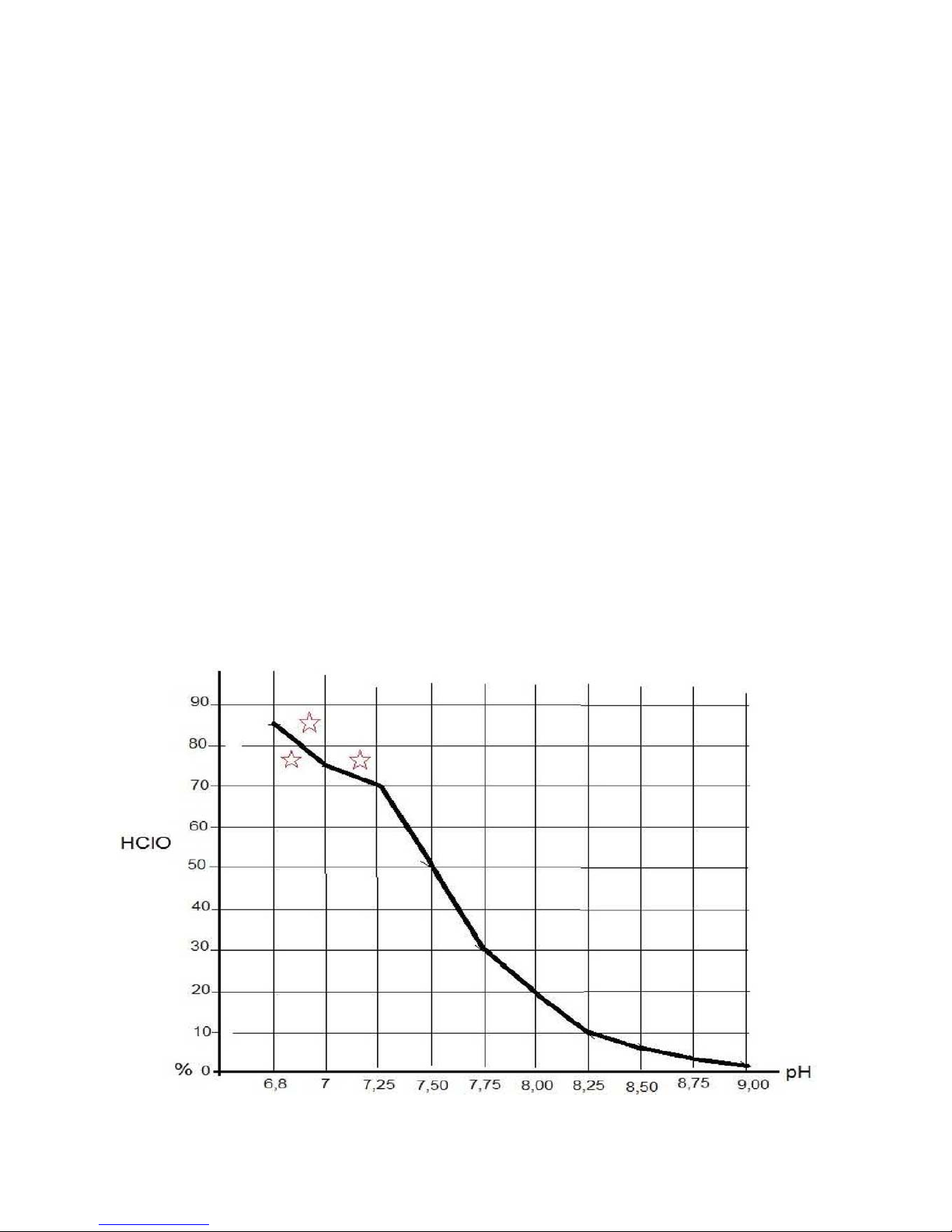
c) A high pH value has a low HCIO % (Hypochlorous) and a high CIO % (hypochlorite).
HCIO is actually the oxidant-disinfectant agent in the swimming pool; which explains that a pH of
6.8, 7.2 is the most reasonable and recommended depending on the type of swimming pool.
In general, when electrolysis system is used to control pH, an agent must be applied (solid-
liquid) pH-minus. Products based on diluted sulphur are recommended. Avoid hydrochloric
acid (HCI) since this produces a corrosive atmosphere in the place where it is found, even
though it is covered. The use of automatic pH regulators (pumps-instrument) is recommended.
Depending on the pH, the chlorine produced will act differently.
At the recommended pH a higher % of hypochlorous than hypochlorite.
Hypochlorous is much more oxidant-disinfectant (HClO).
This manual suits for next models
3
Table of contents
Popular Swimming Pool Vacuum manuals by other brands

Polaris
Polaris iAquaLink CONTROL VTRX25iQ owner's manual

SmartPool
SmartPool Nitro NC71RC Operation manual

Aqua Quip
Aqua Quip JET-VAC Installation guide and owner's manual

Pentair Pool Products
Pentair Pool Products `LIL SHARK GW8000 Installation and user guide

Aquabot
Aquabot Bottom Access operating instructions

AquaVac
AquaVac TigerShark owner's manual


Dirtblaster
Dirtblaster NE445 Assembly instructions

Orca
Orca 300 CL Operating and maintenance instructions

Hayward
Hayward TRX-20 owner's manual

Steinbach
Steinbach Speedcleaner Poolrunner S63 ORIGINAL OWNER'S MANUAL

Maytronics
Maytronics Dolphin X40 Plus quick start guide

Pool Systems
Pool Systems Vektro XL EV90 user manual