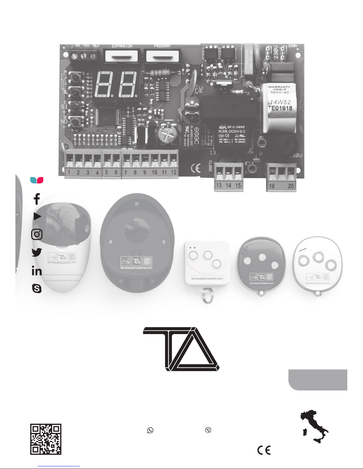
Tecnoautomazione T011S User manual

SAFETY INSTRUCTION
This appliance can be used by children aged from 8
years and above and persons with reduced
physical, sensory or mental capabilities or lack of
experience and knowledge if they have been given
supervision or instruction concerning use of the
appliance in a safe way and understand the hazards
involved. Children shall not play with the
appliance. Cleaning and user maintenance shall not
be made by children without supervision.

INDEX
T011S ver. tS2112 ......................................................................................2
MENU NAVIGATION...................................................................................2
TROUBLE SHOOTING..................................................................................2
-- STAND BY........................................................................3
- REMOTE TRANSMITTING................................................3
5t STOP................................................................................3
tC / td EXTERNAL PHOTOCELL LOGIC 1/2.......................3
tA INTERNAL PHOTOCELL ...................................................3
FH INT.+EXT. PHOTOCELLS....................................................3
Go START..............................................................................3
PE PEDESTRIAN....................................................................3
oP / CL OPEN / CLOSE......................................................3
Po / PC DEAD MAN OPEN/CLOSE ....................................3
FA / LA OPENING LIMIT SWITCH N.C./N.O.......................3
FC / LC CLOSING LIMIT SWITCH N.C./N.O........................3
1H LIMIT SWITCHES ERROR.................................................3
Eo DOMUS INPUT ..............................................................3
rt RANGE TEST REMOTE....................................................3
EL ELECTRIC-LOCK..............................................................3
oC DOMUS REMOTE...........................................................3
0t CONTROL BOARD DAMAGED........................................3
1t TEST PHOTOCELLS FAILED..............................................3
5L ASSISTANCE REQUEST....................................................3
9A MOTOR TEST FAILED......................................................3
7A OBSTACLE DETECTED.....................................................3
8A SLOWDOWN OBSTACLE DETECTED...............................3
FF MEMORY FULL...............................................................3
00 a 99 MOTOR STRESS....................................................3
INSTALLING RADIO MODULE......................................................................3
TYPICAL INSTALLATION..............................................................................3
CONNECTIONS...........................................................................................4
GLOSSARY..................................................................................................5
STAND BY ..........................................................................................5
OPENING ...........................................................................................5
PAUSE................................................................................................5
CLOSING ............................................................................................5
STOP OPENING ..................................................................................5
STOP CLOSING....................................................................................5
CLOSING ............................................................................................5
INPUT IS ACTIVATED ..........................................................................5
START COMMANDS ...........................................................................5
SAFETY COMMANDS .........................................................................5
STANDARD WORKING CYCLE..............................................................5
MOTOR......................................................................................................6
A1 STANDARD WORKING TIME.....................................................6
A2 SLOWDOWN WORKING TIME..................................................6
A3 START UP TIME .......................................................................6
A5 STANDARD FORCE...................................................................6
A6 SLOWDOWN FORCE................................................................6
A7 STANDARD OBSTACLE DETECTION THRESHOLD.......................6
A8 SLOWDOWN OBSTACLE DETECTION THRESHOLD....................6
A9 MOTOR BRAKE........................................................................6
SENSOR OPERATING MODE........................................................................7
FUNCTIONS................................................................................................9
F0 AUTO-CLOSE TIME...................................................................9
F1 PEDESTRIAN WORKING TIME.................................................9
F2 CLOSING KICK..........................................................................9
F3 BLINKING TIME........................................................................9
F4 KICK BACK AT OPENING...........................................................9
F5 and F6 STANDARD, COMMUNITY MODE, STEP BY STEP ..........9
F7 FAST CLOSURE.........................................................................9
F8 PHOTOCELLS LOGIC.................................................................9
L0 ELECTRIC LOCK........................................................................9
L1 COLD WINTER FUNCTION........................................................9
L4 RECOVERY CYCLE...................................................................10
L5 ASSISTANCE REQUEST COUNTER...........................................10
L6 WORKING CYCLE COUNTER...................................................10
L7 FLASHING LAMP MODE........................................................10
TEST.........................................................................................................10
t1 PHOTOCELLS TEST.................................................................10
t2 MOTOR TEST.........................................................................10
PER-PROGRAMMED CONFIGURATIONS....................................................11
d0 FACTORY CONFIGURATION....................................................11
REMOTE CONFIGURATION .......................................................................12
r0 ERASE A REMOTE KEY............................................................12
SAVING A REMOTE KEY....................................................................12
r1 START ........................................................................12
r2 STOP .........................................................................12
r3 PEDESTRIAN ..............................................................12
r4 FAST CLOSURE ...........................................................12
r5 ERASE ALL REMOTE CONTROLS ..........................................12
PROGRAMMABLE RADIO FUNCTIONS..............................................12
r6 OPEN, CLOSE, DEAD MAN, RANGE TEST, EL.-LOCK.....12
r7 OPEN, CLOSE, DEAD MAN, RANGE TEST, EL.-LOCK ....12
r8 OPEN, CLOSE, DEAD MAN, RANGE TEST, EL.-LOCK.....12
FAR REMOTE SAVING.......................................................................12
TERMINAL BLOCK INPUTS........................................................................13
no DISABLED...............................................................................13
5t STOP .....................................................................................13
tC EXTERNAL PHOTOCELL LOGIC 1 ............................................13
td EXTERNAL PHOTOCELL LOGIC 2.............................................13
tA INTERNAL PHOTOCELL ..........................................................13
Go START....................................................................................13
PE PEDESTRIAN..........................................................................13
oP CL /OPEN/CLOSE .................................................................13
Po PC /DEAD MAN OPEN/CLOSE ..............................................13
FA LA /OPENING LIMIT SWITCH N.C. / N.O. .............................13
FC LC /CLOSING LIMIT SWITCH N.C. / N.O...............................13
Eo DOMUS (NO).........................................................................13
EL ELECTRIC-LOCK ...............................................................13
PROGRAMMING PROCEDURE..................................................................14
P1 SEMI-AUTOMATIC PROGRAMMING..............................14
P3 AUTOMATIC PROGRAMMING........................................14
OBSTACLE PROGRAMMING......................................................................15
P6 OBSTACLE PROGRAMMING ..........................................15
INTRODUCTION DOMUS MODULE...........................................................16
RECYCLE ..........................................................................................17
www.tecnoautomazione.com Pag. 1 / 17
T011S ver. tS2111
www.tecnoautomazione.com Pag. 2 / 17
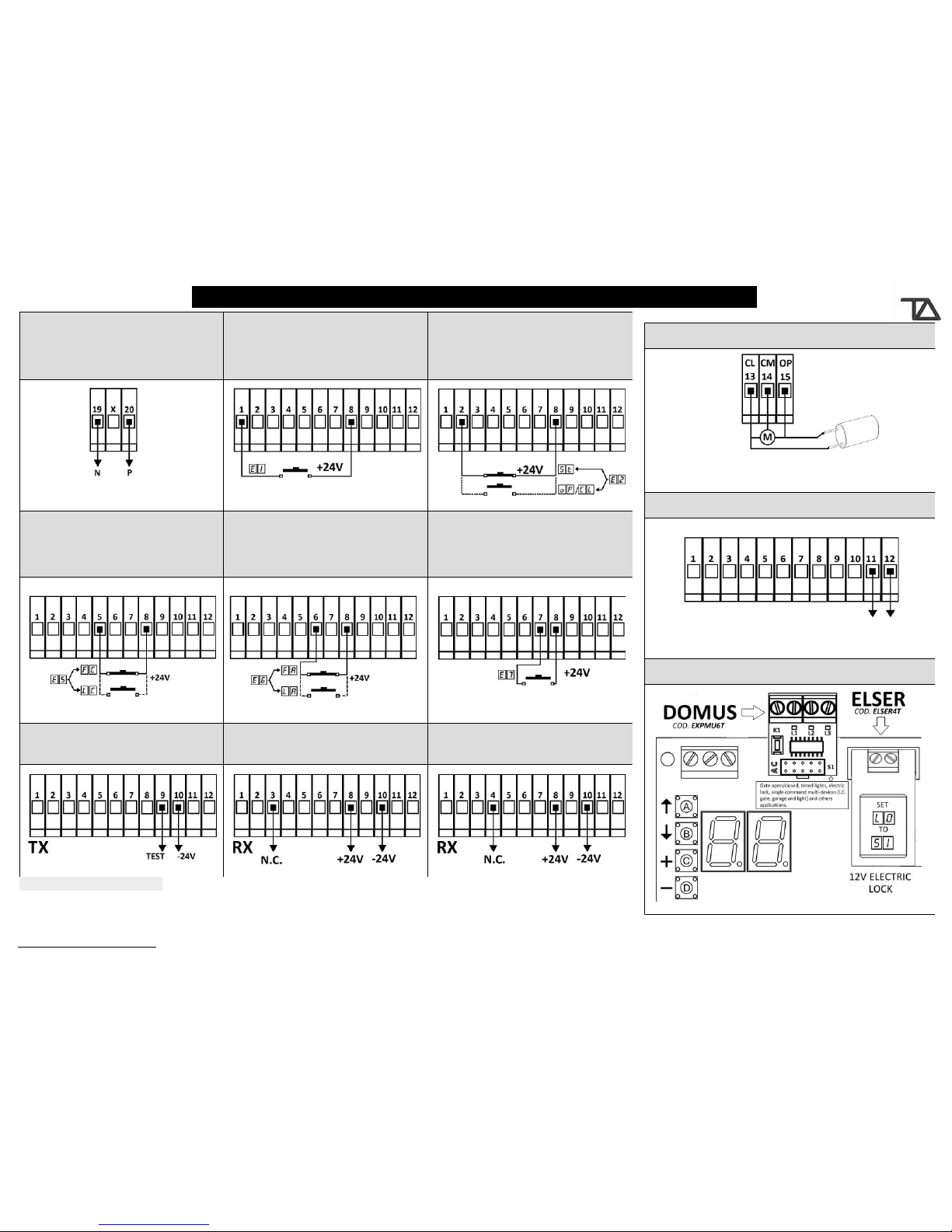
INPUT FUNCTIONS PIN INPUT
Go Start – oP Open – CL Close – Po Dead man open –
PC Dead man close – Eo Domus– EL electric-lock 1 8 E1
no disabled - St Stop – oP open – CL close 2 8 E2
no disabled - tC external photocell logic 1 –
td external photocell logic 2 3 8 E3
no disabled - tA internal photocell - EL Electric-lock 4 8 E4
no disabled - FC closing limit switch N.C. -
LC closing limit switch N.O. 5 8 E5
no disabled - FA opening limit switch N.C.
LA opening limit switch N.O. 6 8 E6
PE Pedestrian – oP Open – CL Close – Po Dead man
open – PC Dead man close – Eo Domus –
EL electric-lock
7 8 E7
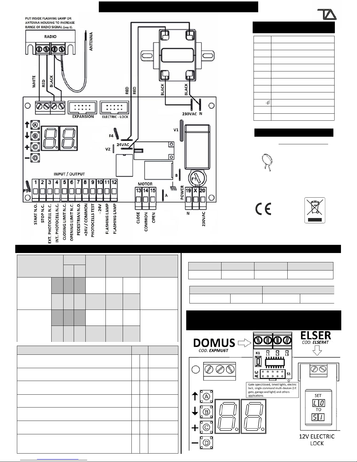
BOARD’S COMPONENTS
AButton A
BButton B
CButton C
DButton D
F1 250 VAC power fuse 5A
F4 Resettable fuse 24V 1.6A
F5 Resettable fuse 24V 0.6A
A B C
Ground terminals
CN Primary varistor
V1 Secondary varistor
V2 Terminal block pins
1 to 20 Button A
RESETTABLE FUSE
AFTER A SHORT-CIRCUIT:
•TURN OFF THE
CONTROL BOARD.
REMOVE THE SHORT-
CIRCUIT.
•WAIT FOR 60
SECONDS OR MORE.
TURN ON THE
CONTROL BOARD.
F4/ F5
INPUTS CONNECTION OUTPUTS CONNECTION
DOMUS Multi functions module (optional)
ELSER 12 Volt Electric lock module (optional)
MOTORS
CLOSE
COMMON
OPEN
Motor A 13 14 15
FLASHING LAMP 24V 20W 24VDC 300 mA
11 12 8 +10 -
PHOTOCELLS
24 VDC
TYPE PIN INPUT
+-
EXTERNAL
(closing)
TX 910
E3
RX 810 Normally
Closed 3 8
INTERNAL
(opening)
TX 910
E4
RX 810 Normally
Closed 4 8
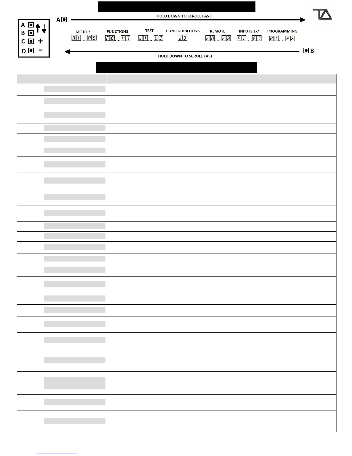
MENU NAVIGATION
DISPLAY REPORT
DISPLAY DESCRIPTION
-- STAND BY The control board is waiting for a command.
-. REMOTE TRANSMITTING A remote key is pressed. The display showing a dot.
5t STOP Stop input open ( Terminal block 2 Normally closed, E2 = 5t).
Stop remote key pressed, stored using r2 function.
tC / td EXT. PHOTOCELL 1/2 External photocell input open ( Terminal blocks 3,4 Normally closed, E3 = tC/tD ).
tA INT. PHOTOCELL Internal photocell input open ( Terminal block 4 Normally closed, E4 = tA ).
FH INT.+EXT. PHOTOCELLS External + Internal photocell inputs open.
Go START Start input closed ( Terminal block 1 Normally open , E1 = Go ).
Start remote key pressed, stored using r1 or r4 functions.
PE PEDESTRIAN Pedestrian input closed ( Terminal block 7 Normally open, E7 = PE).
Pedestrian remote key pressed, stored using r3 function.
oP / CL OPEN / CLOSE Open/Close input closed ( Terminal block 1,2,7 Normally open, E1, E7 = oP / CL ).
Open/Close remote key pressed. Stored using programmable radio functions r6, r7, r8.
Po / PC DEAD MAN OPEN/CLOSE Dead man open/close input closed (Terminal block 1,7 Normally open , E1, E7 = Po / PC).
Dead man open/close remote key pressed. Stored using programmable radio functions.
FA / LA OPENING LIMIT SWITCH Opening limit switch open/closed ( Terminal block input 6 N.C/N.O., E6 = FA N.C./ LA N.O. ).
FC / LC CLOSING LIMIT SWITCH Closing limit switch open/closed ( Terminal block input 5 N.C. /N.O., E5 = FC N.C./ LC N.O. ).
1H LIMIT SWITCHES ERROR Opening + Closing limit switches activated at the same time.
Eo DOMUS INPUT Domus input closed (Terminal block 1,7 Normally open , E1, E7 = Eo).
rt RANGE TEST Range test remote key pressed, stored using programmable radio functions.
EL ELECTRIC-LOCK Electric-lock input closed ( Terminal block 1,4,7 N.O. E1, E4, E7 = EL ) .
Electric-lock remote key pressed. Stored using programmable radio functions.
oC DOMUS REMOTE Domus remote key pressed, stored using H1, H2, H3 or H4 (DOMUS EXPANSION).
0t CONTROL BOARD DAMAGED Control board damaged, replace it.
1t PHOTOCELL ERROR Parameter t1 PHOTOCELLS TEST is set to SI ENABLED. The photocells test failed: wiring error,
installation error or damaged device.
9A MOTOR ERROR Parameter t2 MOTOR TEST is set to SI ENABLED. The motor test failed: wiring error, thermal state,
burnt fuse, or damaged motor.
7A OBSTACLE DETECTED
Parameter A7 STANDARD OBSTACLE THRESHOLD is enabled (set from 00 to 99). An obstacle has
been detected during the standard working time A1. Causes: obstacle on the gate pathway or tuning
error.
8A SLOWDOWN OBSTACLE
DETECTED
Parameter A8 STANDARD OBSTACLE THRESHOLD is enabled (set from 00 to 99). An obstacle has
been detected during the slowdown working time A2. Causes: obstacle on the gate pathway or
tuning error.
FF MEMORY FULL You are trying to store a remote but the control board memory is full. The remote cannot be stored.
Erase a remote to save a new one (r0 single erase or r5 total erasing).
From 00
to 99 MOTOR STRESS During opening and closing the display shows motor stress. The stress is shown as number from 00
OFF to 99 MAX.
www.tecnoautomazione.com Pag. 3 / 17
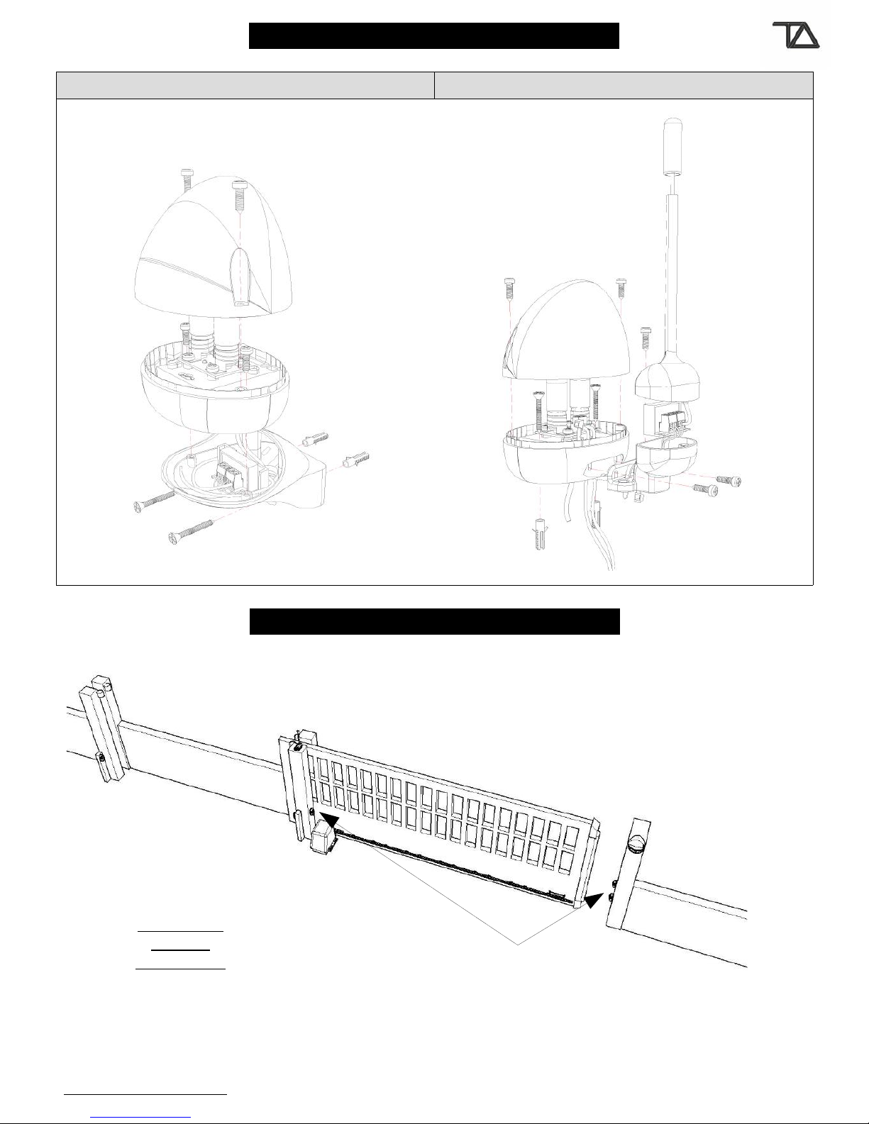
INSTALLING RADIO MODULE
You can choose to install the radio module inside the flashing lamp or antenna to increase the signal range.
FLASHING LAMP BASE RADIO-ANTENNA HOUSING
TYPICAL INSTALLATION
www.tecnoautomazione.com Pag. 4 / 17
RADIO
BODY
BODY
RADIO
BASE
LIGTHS
(max 10W -24V)
COVER
COVER
ANTENNA
COVER
ANTENNA
BASE
Screws and stops not included.
3.5mm. x 13mm.
3.5mm. x 13mm.
4 mm. x 35mm.
4 mm. x 35mm.
stop Ø 6mm
stop Ø 6mm
3.5 mm. x 9mm.
3.5 mm. x 9mm.
Antenna
Flashing lamp
External photocells
wire to input 3
INTERNAL
OF THE
PROPERTY
Internal photocells
wire to input 4
Motor
CONNECTIONS
www.tecnoautomazione.com Pag. 5 / 17
A1..A9
MOTOR
13: CLOSE 14: COMMON 15: OPEN
FLASHING LAMP
24 VAC 20 WATT
INSTALLING OPTIONAL MODULES: DOMUS AND ELECTRIC-LOCK
POWER SUPPLY 230 VAC E1
START Go, OPEN oP, CLOSE CL,
DEAD-MAN OPEN Po,
DEAD-MAN CLOSE PC, DOMUS Eo,
ELECTRIC-LOCK EL
E2 DISABLED no, STOP 5t,
OPEN oP, CLOSE CL
E5 CLOSING LIMIT SWITCH N.C. FC
CLOSING LIMIT SWITCH N.A. LC E6 OPENING LIMIT SWITCH N.C.FA
OPENING LIMIT SWITCH N.A.LA E7
PEDESTRIAN PE, OPEN oP,
CLOSE CL, DEADMAN-OPENN Po,
DEAD-MAN CLOSE PC, DOMUS Eo,
ELECTRIC-LOCK EL
PHOTOCELLS TRANSMITTER E3 EXTERNAL PHOTOCELLS N.C. tC E4 DISABLED no
INTERNAL PHOTOCELLS N.C. tA
EACH INPUT CAN BE DISABLED by settings its value to no. Inputs 2,3, and 4 have auto-enable functionality if the input is disabled
(= no) and a normally closed contact is being wired to 2 – 8 , 3 – 8 , and 4 – 8 the control board sets inputs value to 5t stop (2 –
8), tC external photocell logic 1 (3 – 8), and tA internal photocell (4 – 8).
GLOSSARY
STAND BY The gate is completely closed and the stop, the external photocells, the internal photocells and the
opening limit switch are not activated. The control board is ready to start a working cycle. In this state the
flashing lamp is off.
OPENING The gate is opening and the flashing lamp blinks quickly (0.3 seconds ON and 0.2 seconds OFF).
PAUSE When the opening is finished the motor is stopped and the flashing lamp is on.
After auto-close time has expired (F0) the gate starts closing.
CLOSING The gate is closing and the flashing lamp blinks slowly (0.6 seconds ON and 0.4 seconds OFF).
STOP
OPENING
The gate has been stopped while it was opening. A new start command begins the closing phase.
In this state the flashing lamp is off.
STOP
CLOSING
The gate has been stopped while it was closing. A new start command begins the opening phase.
In this state the flashing lamp is off.
TYPE OF
INPUTS
The input can be an external input or a remote key.
The external inputs are all objects that can be wired to the terminal block of the control board. Each pin of the
terminal block is associated to a specific function. The safety functions match the normally closed contacts. The
other functions match the normally open contacts. The safety functions are: stop, internal photocell, external
photocell, closing limit switch and opening limit switch. While the others are: start (or fast closure start) and
pedestrian start. The pins of the terminal block can be enabled or disabled by programming parameters E1,
E2, E3, E4, E5, E6, E7. The remote key inputs are all functions linked to a remote key. They are: start,
stop, pedestrian start and fast closure start. The control board doesn't distinguish between the type of inputs
but only between the functions.
INPUT IS
ACTIVATED
An input is activated when its state changes from the standard state. For example a photocell is activated when
the beam from the transmitter to the receiver is broken, while a generic switch, push-button or remote key is
activated when it is pushed down. All these actions are recognized by the control board which shows these
changes on the display. When more inputs are activated at the same time the control board will show only the
most critical input. The order from the most critical to the least critical input is:
St =
stop
tC =
external
photocell
tA =
internal
photocell
Go =
start or fast
closure start
PE =
pedestrian start
FC =
closing limit
switch
FA =
opening limit
switch
START
COMMANDS
The start commands are: start, pedestrian start and fast closure start. They are able to start a working cycle. The
function of start commands depend on F5 and F6 parameters programming.
To know more see F5 and F6 description.
To know how the fast closure start command works see F7 description.
To know how the start command works see Standard Working Cycle.
To know how the pedestrian start command works see Pedestrian Working Cycle.
SAFETY
COMMANDS
The safety commands are: stop, internal photocell and external photocell. The stop commands always stop the
gate. Instead the function of the photocells depend on F8 programming.
To know more see F8 description.
STANDARD
WORKING
CYCLE
A start command has been received when the control board was in stand by state.
The motor works for a total time of A1 plus A2 seconds during the opening and the closing. When a standard
working cycle is in progress, the pedestrian start commands are considered as a start. The working cycle is
finished when the control board returns to stand by state. This functionality can be handled by parameters
programming.
www.tecnoautomazione.com Pag. 6 / 17

MOTOR
STANDARD WORKING
TIME
The opening and closing cycles are subdivided into two phases: The standard phase
A1 and the slowdown phase A2.
A1
→
Programs the duration of the standard phase, during this time the force of the motor is
A5
.
A2
→
Programs the duration of the slowdown phase, during this time the force of the motor is
A6
.
The slowdown phase is performed after the standard phase.
A1 → 0.0 to 9.9 and from 10 to 99 seconds.
A2 → 0.0 to 9.9 and from 10 to 99 seconds.
A1
SLOWDOWN WORKING
TIME
A2
START UP TIME A3 is the start up time of the motor. During this time the force of the motor increases
constantly until it reaches the maximum power and the obstacle detection sensor is
disabled. Each time the motor starts, the first A3 seconds are the start up time.
A3 → 0.1 to 1.5 seconds.
A3
STANDARD FORCE A5 is the force of the motor during the standard working time A1. If A5 increases, the
sensitivity of the sensor decreases. If A5 decreases, the sensitivity of the sensor increases. It
is advisable to choose the required force of the motor first then calibrate the threshold A7.
A5 → 3 to 10.
A5
SLOWDOWN FORCE A6 is the force of the motor during the slowdown working time A2. If A6 increases, the
sensitivity of the sensor decreases. If A6 decreases, the sensitivity of the sensor increases. It
is advisable to choose the required force of the motor first then calibrate the threshold A8.
A6 → 6 to 10.
A6
STANDARD OBSTACLE
DETECTION
THRESHOLD
This parameter will have effect during the standard working time A1. If the control board
detects a motor stress higher than A7, it means that there is an obstacle in the way of the
gate. The control board will make a decision in accordance with its programming as
described in SENSOR OPERATING MODE (see page 7).
When the motor is on and the standard working time is in progress, the control board display
shows the motor stress as number. You can use this value as a feedback value. 00 is the
minimum and 99 is the maximum. The maximum value can be lower than 99. It depends on
the motor. To disable the standard obstacle detection function set A7 = no. To set no
hold down or keep pressing button C until the display shows no. A7 is settable from 00 to
99. After 99 the control board display shows no.
A7 → 00 to 99 and 99 to no (DISABLED).
A7
SLOWDOWN OBSTACLE
DETECTION
THRESHOLD
This parameter will have effect during the slowdown working time A2.
If the control board detects a motor stress higher than A8, it means that there is an
obstacle in the way of the gate. The control board will make a decision in accordance with its
programming as described in SENSOR OPERATING MODE (see page 7).
When the motor is on and the slowdown A2 is in progress, the control board display shows
the motor stress as a number. You can use this value as a feedback value. 00 is the minimum
and 99 is the maximum. The maximum value can be lower than 99. It depends on the motor.
To disable the slowdown obstacle detection function set A8 = no. To set no hold down or
keep pressing button C until the display shows no. A8 is settable from 00 to 99. After 99
the control board display shows no.
A8 → 00 to 99 and 99 to no (DISABLED).
A8
MOTOR BRAKE Motor brake is programmable by 0.01 seconds step. The motor brakes at the end of each
movement. It is useful to minimizing the inertia effects. During the slowdown motor brakes
only if the time lapsed is less than 2 seconds.
A9 → no DISABLED to 50 (0.5 seconds).
A9
www.tecnoautomazione.com Pag. 7 / 17
SENSOR OPERATING MODE
There are two sensor operating modes: Obstacle Detection and Limit switch. They are described in the table below:
OBSTACLE DETECTION LIMIT SWITCH
In this operating mode the motor changes direction. If the direction was
closure, the gate opens completely. If the direction was opening, the
gate closes for 2 seconds. After this time, it stops. A start command will
restart the closing. This functionality is active once per working cycle.
For additional times during the cycle the sensor works as a limit switch.
In this operating mode the motor finishes the
working phase: from Opening to Pause, from
Closing to Stand by.
The operating mode depends on the working phase and parameters programming. The working phases are: opening, opening
slowdown, closing, closing slowdown. The relevant parameters are: A2, A7, A8, E5, E6.
•If A7 is set to no the sensor is disabled during the standard working time. This means that it doesn't work in any
operating mode during the standard working time (A1).
•If A8 is set to no or A2 is equal to 00 the sensor is disabled during the slowdown working time. This means that
it doesn’t work in any operating mode during the slowdown working time (A2).
•If the limit switches inputs are installed (E5=SI and E6=SI): The sensor works in obstacle detection mode.
•If the opening limit switch input is not installed (E6=no) and the opening is in progress: The sensor works in
obstacle detection mode during the standard working time (A1). During the slowdown (A2) the sensor works in
limit switch mode.
•If the opening limit switch input is not installed (E6=no) and the slowdown phase is disabled (A2 = 00): The
sensor works in limit switch mode during the opening.
•If the closing limit switch input is not installed (E5=no) and the closing is in progress: the sensor works in obstacle
detection mode during the standard working time (A1). During the slowdown (A2) the sensor works in limit switch
mode.
•If the closing limit switch input is not installed (E5=no) and the slowdown phase is disabled (A2 = 00): The
sensor works in limit switch mode during the closing.
•If both limit switches inputs are not installed (E5=no and E6=no): The sensor works in obstacle detection mode
during the standard working time(A1). During the slowdown working time (A2) the sensor works in limit switch
mode.
•If both limit switches inputs are not installed (E5=no and E6=no) and the slowdown phase is disabled
(A2 = 00): The sensor works in limit switch mode.
Obstacle Detection Limit Switch Disabled
Opening
E6 = SI
or
E6 = no and A2 enabled
E6 = no and A2 = 00 A7 = no
Opening
Slowdown E6 = SI E6 = no
A8 = no
or
A2 = 00
Closing
E5 = SI
or
E5 = no and A2 enabled
E5 = no and A2 = 00 A7 = no
Closing
Slowdown E5 = SI E5 = no
A8 = no
or
A2 = 00
www.tecnoautomazione.com Pag. 8/ 17
WORKING
PHASE
OPERATING
MODE
FUNCTIONS
AUTO-CLOSE TIME The gate remains open for F0 seconds at the end of opening before begging the closing phase.
To disable hold down @C button until display shows St.
F0
PEDESTRIAN
WORKING TIME
It is the motor working time during a pedestrian working cycle. The slowdown phase is skipped during the
opening and executed during the closing. The slowdown time is automatically managed by the control
board during a pedestrian working cycle.
F1
CLOSING KICK When the gate is closing and the slowdown is finished, a ramp pulse of F2 seconds is executed by motor
A to facilitate locking of the electric lock.
F2
BLINKING TIME Before starting the motor, the flashing lamp blinks for F3 seconds. After this time the flashing lamp will
continue blinking and the motor will start.
F3
KICK BACK AT
OPENING
F4 = SI → ENABLED F4 = no → DISABLED
Before opening the motor closes for 0.5 seconds to facilitate the release of the electric lock.
F4
START COMMANDS
FUNCTIONALITY
STANDARD MODE
F6 = no and F5 = no
During the opening :
The start commands stop the
opening.
During the closing :
The start commands stop the
closing and begin the opening.
COMMUNITY MODE
F6 = SI
During the opening :
The start commands don't have
any effect.
During the closing :
The start commands stop the
closing and begin the opening.
STEP-BY-STEP MODE
F6 = no and F5 = SI
During the opening :
The start commands stop the gate.
During the closing:
The start commands stop the gate.
F5
F6
FAST CLOSURE If F7 = SI → All start commands begin the fast closure function.
If F7 = no → Only remote keys programmed through r4 begin the fast closure function.
Fast closure means: During the first opening once the external photocells have been activated the gate
will start to close after 5 seconds.
For safety reasons it is advisable to enable this function only when two pairs of external photocells are
installed as shown in TYPICAL INSTALLATION .
F7
PHOTOCELLS LOGIC F8 = SI → SLIDING MODE
D uring the opening:
If the internal photocell is activated the control
board stops the opening and starts the closing.
After 3 seconds the closure is stopped and the
control board state is stop-opening. The activation
of the external photocell doesn't have any effect
Instead.
During the closing:
If the external photocell is activated the control
board stops the closing and starts the opening.
The activation of the internal photocell doesn't
have any effect instead.
F8 = no → SWING MODE
During the opening:
While the internal photocell is activated the control
board stops the opening. When the internal photocell is
deactivated the control board continues the opening. The
activation of the external photocell doesn't have any
effect instead.
During the closing:
If the external photocell is activated the control board
stops the closing and starts the opening.
If the internal photocell is activated the control board
stops the closing and waits for the opening. The opening
starts only when the internal photocell is deactivated.
F8
ELECTRIC LOCK L0 = SI → ENABLED
The electric-lock module is managed. The
module must be installed on the expansion
socket.
L0 = no → DISABLED
The electric-lock is not managed. The module is not
installed on the expansion socket.
L0
COLD WINTER
FUNCTION
L1 is settable from 0 to 8 minutes. For instance, by setting L1 to 3 that means that the motor will
remain powered up at minimum power for 3 minutes out of 8. This function can be helpful in very cold
countries.
L1
www.tecnoautomazione.com Pag. 9 / 17

FUNCTIONS
SAFETY BY PASS
FUNCTION
L4
L4 = SI → ENABLED L4 = no → DISABLED
L4 allows to open/close the gate even if stop or photocells inputs are detected (I.E. damaged
photocells). It requires a normally open push button wired on the terminal block 1-8 or 7-8.
E1 / E7 must be set to one of following functions: Go start, oP open, CL close.
When a photocell or stop inputs are detected, you can open and close the gate following these steps:
1. Press the push button wired on input 1-8 or 7-8.
2. Release the push button. The flashing lamp will turn on.
3. Within 2.5 sec hold down the push button.
4. The gate opens/closes while the button is pressed. To stop the gate, release the push button.
FOR SAFETY REASONS, IT IS HIGHLY RECOMMENDED TO ENABLE THE L4 FUNCTION ONLY ON WIRED
DEVICES (I.E. KEY SELECTORS).
ASSISTANCE
REQUEST
COUNTER
L5 = no → DISABLED
When the gate has completed L5 working cycles the display shows 5L. Each 20 minutes the flashing
lamp is on for 1 minute. This function helps you to program the assistance of the gate.
L5 works in these range:
from 0.1 to 0.9 → from 1 to 9 working cycles
from 1.1 to 1.9 → from 10 to 90 working cycles
from 2.1 to 2.9 → from 100 to 900 working cycles
from 3.1 to 3.9 → from 1000 to 9000 working cycles
from 4.1 to 4.9 → from 10000 to 90000 working cycles
from 5.1 to 5.9 → from 100000 to 900000 working cycles
For instance if L5 = 3.3 the assistance request function is activated after 3000 working cycles.
Press a control board button to clear the assistance request.
L5
WORKING CYCLE
COUNTER
L6 is the gate working cycles counter from 1 to 9 millions. The display shows the working cycles as
power ten. For instance if a gate has completed 1365 working cycle then L6 shows 3.1. Pressing
button D the display shows the complete value from left to right → :
3.1 2.3 1.6 0.5
1 3 6 5
L6
FLASHING LAMP
MODE
L7 = 00
STANDARD MODE: the flashing lamp blinks fast during opening, slow during closing and it is on before closing.
L7 = 01
FIX MODE: the flashing lamp is on during opening, closing and before closing.
L7
TEST
PHOTOCELLS
TEST
t1 = SI → ENABLED t1 = no → DISABLED
Each time the gate starts, the control board checks the photocells.
If no errors are detected the motors can be started. Vice versa the motors cannot start and the control
board display shows 1t.
t1
MOTORS TEST t2 = SI → ENABLED t2 = no → DISABLED
Before each gate movement the motor is tested. If the motor is in thermal protection state or it is badly
connected the display shows 9A. When the test fails the gate does not move.
t2
www.tecnoautomazione.com Pag. 10 of 17

PRE-PROGRAMMED CONFIGURATIONS
FACTORY
CONFIGURATION
d0
Keep pressing button A or B until the display shows d0. The control board shows
no. To set the factory settings hold down button C until the display shows --. The
factory configuration does not have any effect on radio memory.
MOTOR TERMINAL BLOCK FUNCTIONS
A1 STANDARD TIME 14 sE1 INPUT 1 Go START F0 AUTO CLOSE TIME 10 s
A2 SLOWDOWN TIME 7 sE2 INPUT 2 no DISABLED F1 PEDESTRIAN TIME 7 s
A3 START UP TIME 0.8 sE3 INPUT 3 tC EXT. PHOTOCELL LOGIC 1 F2 CLOSING KICK 0 s
A5 STANDARD FORCE 6/10 E4 INPUT 4 no DISABLED F3 PRE-BLINKING TIME 1 s
A6 SLOWDOWN FORCE 10/10 E5 INPUT 5 FC CLOSING LIMIT SWITCH F4 KICK BACK AT OPENING 1 s
A7 STANDARD OBSTACLE
THRESHOLD
no E6 INPUT 6 FA OPENING LIMIT SWITCH F5 STEP-BY-STEP no
A8 SLOWDOWN OBSTACLE
THRESHOLD
no E7 INPUT 7 PE PEDESTRIAN F6 COMMUNITY MODE no
A9 MOTOR BRAKE no F7 FAST CLOSURE no
F8 PHOTOCELLS LOGIC SI
TEST PROGRAMMABLE RADIO FUNCTIONS L0 ELECTRIC-LOCK no
t1 PHOTOCELLS no r6 DEAD MAN OPEN Po L1 COLD WINTER 0 m
t2 MOTOR SI r7 DEAD MAN CLOSE PC L4 SAFETY BY PASS no
r8 RANGE TEST rt L5 ASSISTANCE REQUEST no
L7 FLASHING LAMP MODE OO
s → seconds no → DISABLED
m → minutes 5I → ENABLED
www.tecnoautomazione.co m Pag. 11 / 17
REMOTE
SINGLE ERASE Keep pressing A or B button until the display shows r0. After a few seconds the control
board starts scanning for stored codes. Each code showed is a remote key ID. To erase hold down
button C. The display blinks showing remote key ID. When the display is off the remote key ID has
been erased.
r0
SAVING A REMOTE
KEY
A remote key is configurable as: START r1, STOP r2, PEDESTRIAN r3 ,FAST CLOSURE r4 or
PROGRAMMABLE FUNCTION from r6 to r8. Press A or B to select r1, r2, r3 , r4, r6, r7
or r8. After a second, the display shows =_. Hold down a remote key. The display shows ._. Push
down the button C on the control board to confirm. After storing, the display shows the remote key
ID. The control board holds up to 99 codes. If the memory is full, the display shows FF when trying
to store a new remote key.
•r1 START
The start function begins a Standard Working Cycle : The motor works for a total time of A1
plus A2 seconds during the opening and the closing.
•r2 STOP
The stop function stops the gate.
•r3 PEDESTRIAN
The pedestrian function begins a Pedestrian Working Cycle: The motor works for a total time
of F1 seconds.
•r4 FAST CLOSURE
During the opening: once the external photocells have been activated, the gate starts closing
after 5 seconds.
During the pause time F0: once the external photocells have been activated, the gate starts
closing.
For safety reasons it is advisable to link this function to a remote key only when two pairs of
external photocells are installed as shown in TYPICAL INSTALLATION .
r1 START
r2 STOP
r3 PEDESTRIAN
r4 FAST
CLOSURE
ERASE ALL REMOTE
CONTROLS Keep pressing A or B button until the display shows r5. After a few seconds the control board shows
no. To erase all stored codes, hold down button C until the display stops flashing SI (YES).
r5
PROGRAMMABLE
RADIO FUNCTIONS
The programmable radio functions are: open only oP, close only CL, dead man open Po, dead
man close PC and rt range test. To save see Saving a remote key.
To set a function select r6, r7, or r8 by pressing button A or B. Hold down button D. The display
blinks showing r6, r7, or r8. When the display stop blinking release button D. Selecting the
function using buttons C and D. The
oP OPEN opens the gate.
CL CLOSE closes the gate.
Po/PC DEAD MAN opens/closes the gate even the safety inputs are activated ( I.E. stop input). The
dead man functions works until the buttons of the remote is pressed.
rt RANGE TEST turns on the flashing lamp while the remote key is pressed. Range test function
helps you to find the best antenna location.
EL ELECTRIC LOCK activates the electric-lock module with remote key. For instance It may be useful
when you want to unlock an electric-lock installed on a pedestrian gate beside the electric gate.
(Available on the terminal block inputs, too).
r6
r7
r8
FAR REMOTE SAVING
You can add a remote key to the control board memory without opening the protective housing. You need a remote previously
stored. How-to:
1. Open the gate (completely).
2. Break the photocell beam ( Flashing lamp is off).
3. Hold down the remote key previously stored. After 5 seconds the flashing lamps blinks.
4. Release the remote key. The flashing lamp is on (without blinking).
5. Within 10 seconds press unsaved remote key. The flashing lamp blinks three times. The flashing lamp is off. The
remote key has been saved as START (r1).
www.tecnoautomazione.com Pag. 12 / 17
INPUTS
Each terminal block is programmable by a configuration parameter.
E1 → input 1, E2 → input 2 , E3 → input 3, E4 → input 4, E5 → input 5, E6 → input 6, and E7 → input 7.
FUNCTIONS DESCRIPITION TYPE TERMINAL BLOCK INPUT
no Disable the chosen input. The inputs E2, E3and E4 have the
auto-enable function. When the terminal block input is disabled
and a normally closed contact is wired to the input, the control
board sets that input equal to the SAFETY value. For instance, if E2
is set to no and a normally closed contact is wired to input 2, the
control board sets E2 to 5t.
FROM INPUT 1 TO 7
E1, E2, E3, E4, E5, E6, E7
=
no
DISABLED
St
The stop function stops the gate movement. N.C.
SAFETY INPUT 2 → E2 = 5t
STOP
tC During the closing: the external photocells stop the closing and
start the opening.
During the opening: the external photocells do not have any effect.
N.C.
SAFETY INPUT 3 → E3 = tC
EXTERNAL
PHOTOCELL LOGIC 1
td
Same like tC but the opening starts even if the external photocell is
detecting an obstacle.
N.C.
SAFETY INPUT 3 → E3 = td
EXTERNAL
PHOTOCELL LOGIC 2
tA During the opening: The internal photocell stops the opening and
starts the closing. After 2 seconds the closure is stopped. A start
command restore the closing.
During the closing: the internal photocells does not have any effect.
N.C.
SAFETY
INPUT 4 → E4 = tA
INTERNAL
PHOTOCELL
Go The START function begins a STANDARD WORKING CYCLE:
The gate opens for A1 plus A2(slowdown) seconds, stays open for
F0 seconds, and then closes. N.O. INPUT 1 → E1 = Go
START
PE The PEDESTRIAN START function begin a PEDESTRIAN WORKING
CYCLE: the gate opens for F1 seconds. N.O. INPUT 7 → E7 = PE
PEDESTRIAN
oP CL/The open/close function opens/close the gate. The close function
does not work if the gate is closed. It works even the gate closed but
only at the power on.
N.O.
INPUT 1 → E1 = oP CL/
INPUT 2 → E2 = oP CL/
INPUT 7 → E7 = oP CL/
OPEN / CLOSE
Po PC/The dead-man functions allow the opening/closing of the gate even
if the safety inputs are activated ( I.E. stop input) and the
programmed input is activated.
N.O. INPUT 1 → E1 = Po PC/
INPUT 7 → E1 = Po PC/
DEAD-MAN
OPEN / CLOSE
FA LA/The OPENING LIMIT SWITCH terminates the opening phase.
FA → Normally open limit switch.
LA → Normally closed limit switch.
If you are using magnetic limit switches (FNCMF5T) set E6 = LA.
N.C.
/
N.O.
INPUT 6 → E6 = FA / LA
OPENING LIMIT
SWITCH
FC LC/The CLOSING LIMIT SWITCH terminates the closing phase.
FC → Normally open limit switch.
LC → Normally closed limit switch.
If you are using magnetic limit switches (FNCMF5T) set E5= LC.
N.C.
/
N.O.
INPUT 5 → E5 = FC / LC
CLOSING LIMIT
SWITCH
Eo
DOMUS
The domus command does not have any effect on the gate status. It
can be used in combination with the domus expansion. For instance
a light can be turned on through the key selector without starting
the gate.
N.O.
FROM INPUT 1 TO 7
E1, E2, E3, E4, E5, E6, E7
=
Eo
EL The ELECTRIC-LOCK function activates the electric-lock with a push
button wired at the terminal block input. For instance It may be useful
when you want to unlock an electric-lock installed on a pedestrian gate
beside the electric gate. (Available on remote controls, too).
N.O.
INPUT 1 E1 = EL
INPUT 4 E4 = EL
INPUT 7 E7 = EL
ELECTRIC-LOCK
www.tecnoautomazione.com Pag. 13 / 17

PROGRAMMING PROCEDURE
MOTOR
WORKING TIME
PROGRAMMING
YOU NEED:
•START Button
For saving a remote key as START, using buttons A/B to select r1. hold down the remote key
then press button C on the control board.
•Check the motor direction.
•Check if the terminal block inputs work properly.
P1 SETS:
•A1 → Motor A standard working time
•A2 → Motor A slowdown working time
•F0 → Automatic close time
P1→ __ Select P1 using buttons A/B. When display show __ press START.
A1 Motor A opens. When the opening is almost complete press START to go the
next step.
A2 Motor A slows down. When the gate reaches the opening limit switch the control
board goes to the next step automatically. If you do not use the opening limit
switch, press START to go the next step.
F0 The motor is off. The flashing lamp is on. The display show the time lapsed.
When you want to close the gate press a START. The automatic close time will
be equal to the value shown on the display.
After the programming you can modify each parameter manually
P1
AUTOMATIC
PROGRAMMING
P3
YOU NEED:
•START Button
For saving a remote key as START, using buttons A/B to select r1. hold down the remote key
then press button C on the control board.
•Check the motor direction.
•Check if the terminal block inputs work properly.
•The opening limit switch installed or mechanical gate stop in opening.
P3 SETS:
•A1 → Motor A standard working time
•A2 → Motor A slowdown working time
•F0 = 10 seconds (Auto-close time)
HOW-TO:
•Select P3 using buttons A/B. After a few seconds display shows __.
•Press START →
The gate opens. When the gate reaches the opening limits switch or the ground stop the
control board stops the motor. The flashing lamp is on.
Display shows count-down from 10 to 0 seconds then gate starts closing.
If you do not use the opening limit switch and the control board does not detect the mechanical
gate stop, press any input to terminate the programming. Set the control board parameters manually
or select the semi-automatic procedure P1.
www.tecnoautomazione.com Pag. 14 / 17

PROGRAMMING OBSTACLE SENSOR
OBSTACLE
PROGRAMMING
P6 helps you to program the obstacle detection sensor.
P6 sets:
•A7 → Motor A standard obstacle detection threshold
•A8 → Motor A slowdown obstacle detection threshold
HOW-TO:
1. The gate must be closed.
2. Selecting P6 using buttons A/B.
3. When display shows -- press a START command.
4. The display shows *1 motor closing pushing on the mechanical stop. The control board has
detected the maximum motor stress when an obstacle is in the path of the gate.
5. The display shows *2 motor A opens for 4 seconds. motor stops. The control board has detected
the motors stress without any obstacle.
6. The display shows *3 the gate returns to initial position. When motor stops the procedure is
finished.
If the display shows 9P an error has occurred during the procedure.
Any command during the steps 2,3,4,5,6 stops P6 programming and display will show 9P.
After programming you can modify the obstacle parameters manually. For instance you can disable
slowdown obstacle detection setting A8 to no.
P6
www.tecnoautomazione.com Pag. 15 / 17
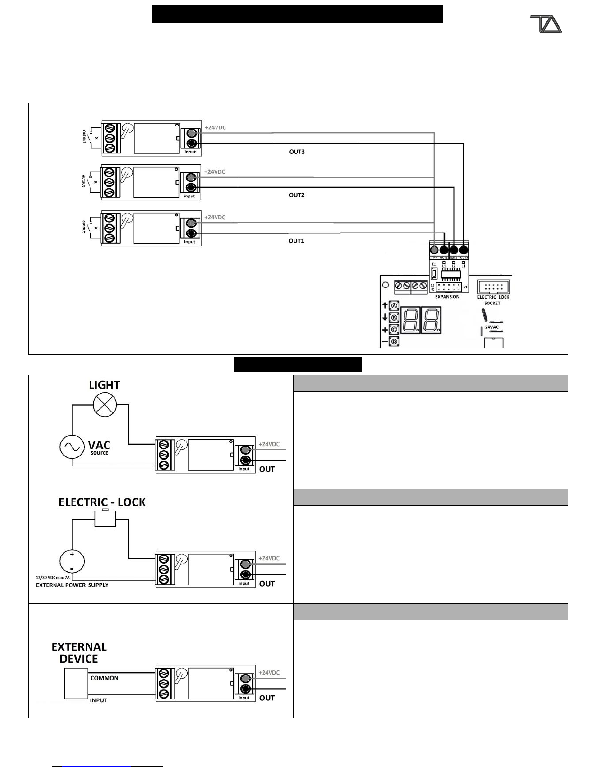
INTRODUCTION DOMUS MODULE
The DOMUS expansion consists of a DOMUS MODULE and up to three RELAY MODULES. The DOMUS module expands
the control board with three open collector outputs. Each output controls a relay module. The DOMUS module has a
push-button K1 to select the outputs menu and three LEDs: L1, L2 and L3. Each LED is linked to a relay status. The LED is ON when
the corresponding RELAY output is closed . The DOMUS expansion may be used to control a variety of different applications, as for
instance timed lights controlled by remote, courtesy lights, flashing lamp, electric-lock, traffic lights, and extending an alarm
system.
TYPICAL APPLICATIONS
LIGHTS
The lights can be controlled by terminal block input, remote
key and/or gate status. The most useful functions are: ON,
ON/OFF, ON from 0 to 99 Seconds / Minutes / Hours.
DOMUS controls up to 3 lights. The lights can be controlled
with a single command with different function for each
output (I.E. Turn On output 1 and Turn Off output 2).
ELECTRIC-LOCK
For this application you need of an external DC power
supply and an electric-lock. The electric-lock can be
controlled by terminal block input, remote key and/or gate
status. This application can be used to control additional
electric-lock.
EXTERNAL DEVICE
A control board with the DOMUS can command one or
more external devices. The command can be sent by
terminal block input, remote key and/or gate status. For
instance this application can be used to open or close more
devices at the same time.
www.tecnoautomazione.com Pag. 16 / 17

RECYCLE
For private households: Information on Disposal for Users of WEEE This symbol on the product(s) and /
or accompanying documents means that used electrical and electronic equipment (WEEE) should not
be mixed with general household waste. For proper treatment, recovery and recycling, please take this
product(s) to designated collection points where it will be accepted free of charge. Alternatively, in
some countries, you may be able to return your products to your local retailer upon purchase of an
equivalent new product. Disposing of this product correctly will help save valuable resources and
prevent any potential negative effects on human health and the environment, which could otherwise
arise from inappropriate waste handling. Please contact your local authority for further details of your
nearest designated collection point. Penalties may be applicable for incorrect disposal of this waste, in
accordance with you national legislation. For professional users in the European Union If you wish to
discard electrical and electronic equipment (EEE), please contact your dealer or supplier for further
information. For disposal in countries outside of the European Union This symbol is only valid in the
European Union (EU). If you wish to discard this product please contact your local authorities or dealer
and ask for the correct method of disposal.
www.tecnoautomazione.com Pag. 17 / 17
Table of contents
Popular Garage Door Opener manuals by other brands

Wayne-Dalton
Wayne-Dalton Quantum 3214 Owner installation and user manual

Beninca
Beninca BOB5024E manual

Rollerdor
Rollerdor RD77 installation guide

Wayne-Dalton
Wayne-Dalton Quantum 3000 Series Owner installation and user manual

Assa Abloy
Assa Abloy Highlands HI1000 - HI2000 - HI3000 installation instructions

Chamberlain
Chamberlain BILT B4603T installation manual

Chamberlain
Chamberlain Model MotorLift 1000 owner's manual

Overhead door
Overhead door INFINITY 2000 Installation, Programming, Operating Manual

Chamberlain
Chamberlain Security+ 3112E owner's manual

Craftsman
Craftsman 139.53927 owner's manual

Clifford
Clifford Premier owner's manual

Vimar
Vimar Elvox EFA1 quick start guide


