manuals.online logo
Brands
  1. Home
  2. •
  3. Brands
  4. •
  5. Vimar
  6. •
  7. Garage Door Opener
  8. •
  9. Vimar Elvox EFA1 User manual

Vimar Elvox EFA1 User manual

Viale Vicenza, 14
36063 Marostica VI - Italy
www.vimar.com
EFA1
S6I.EFA.100 08 1611
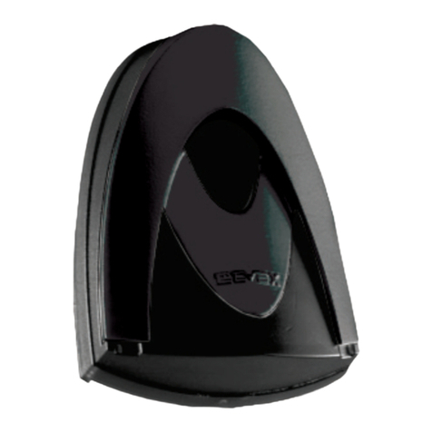
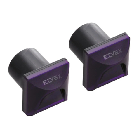
Fotocellula sincronizzata da esterno a parete con possibilità di ruotare il
circuito di 180° (Fig. 2). Costituita da ricevitore (RX) e da un trasmettitore
(TX) a raggi infrarossi modulati.
N.B. è vietato l’uso per riflessione a l’installazione in superfici non rigide
soggette a vibrazioni.
Caratteristiche tecniche:
- Alimentazione:
12 Vac/dc con il ponticello inserito (limiti 10/18 Vac)
24 Vac/dc senza ponticello (limiti 18/32 Vac)
- Assorbimento max.:
a 12 V: Rx 46 mA, Tx (min) 65 mA, Tx (sync.) 37 mA
a 24 V: Rx 55 mA, Tx (min) 54 mA, Tx (sync.) 45 mA
- Portata relè: 1 A a 24 Vdc / 120 Vac
- Tempo di risposta: < 30 ms.
- Temperatura di funzionamento: -20° C ÷ +55° C
- Angolo di rilevazione: Rx ± 20° C
- Angolo raggio emesso: Tx ± 12° C
- Grado di protezione: IP55
- Portata massima: 15 m
N.B. La portata si può ridurre del 50% in presenza di fenomeni atmosfe-
rici: nebbia, pioggia, polvere ecc.
Installazione:
1) Inserire un cacciavite a taglio nella fessura ricavata nel lato inferiore
del coperchio (Fig. 3).
2) Fissare il fondo della fotocellula in parete, applicando dei tasselli,
cercando di ottenere l’allineamento migliore (Fig. 3).
Collegamenti:
1) Selezionare l’alimentazione della fotocellula agendo sul ponticello
JP12 di selezione della tensione. La scelta 12/24 Vac/dc va fatta in
base alla tensione disponibile della centrale sia sul TX che sul RX
(Fig. 4).
JP 12 con ponticello inserito = Alimentazione 12 Vac/dc
JP 12 senza il ponticello = Alimentazione 24 Vac/dc
2) Nel caso di due trasmettitori (TX) vicini, il raggio di uno potrebbe
interferire sull’altro ricevitore non garantendo il corretto funzionamen-
to. Per ovviare questo problema, se disponibile l’alimentazione in
corrente alternata, è possibile utilizzare il sistema di sincronismo che
permette di far funzionare alternativamente le due coppie di fotocellu-
le. Per attivare la funzione di sincronismo si deve togliere il ponticello
SYNC del trasmettitore (TX).
Ponticello “SYNC” inserito = funzionamento normale
Ponticello “SYNC” non inserito = funzione sincronismo
3) Eseguire i collegamenti elettrici in base alla funzione richiesta,
secondo quanto riportato nelle caratteristiche tecniche. Il led bicolore
presente nel ricevitore consente di ottenere una verifica dell’allinea-
mento corretto tra RX e TX..
LED Significato
Spento Alimentazione assente
Rosso Presenza ostacolo, allineamento errato
Lampeggiante Allineamento non perfetto
Verde Allineamento ottimale
4) Eseguita l’installazione della fotocellula. Controllare il funzionamento
interrompendo più volte il fascio (raggio infrarosso); verificare l’accen-
sione del led rosso della ricevente e la commutazione del relè
5) Eseguito il collaudo posizionare il frontalino.
IT EN
Photocell synchronized for surface mounting with possibility to turn the
circuit of 180°. Consisting of receiver (RX) and transmitter (TX) with
modulated infrared rays.
NOTE: use for backscattering the installation on non-rigid surfaces
subject to vibrations is forbidden.
Technical specifications:
- Power supply:
12 Vac/dc with jumper inserted (limits 10/18 Vac)
24 Vac/dc without jumper (limits 18/32 Vac)
- Max. absorption:
at 12 V: Rx 46 mA, Tx (min) 65 mA, Tx (sync.) 37 mA
at 24 V: Rx 55 mA, Tx (min) 54 mA, Tx (sync.) 45 mA
- Relay capacity: 1 A at 24 Vdc / 120 Vac
- Response time:< 30 ms.
- Operating temperature: -20° C ÷+55° C
- Detection angle: Rx ± 20° C
- Radius angle emitted: Tx ± 12° C
- Protection rating: IP55
- Maximum range: 15 m
NOTE: The range may decrease by 50% when there is atmospheric
phenomena: fog, rain, dust, etc.
Installation:
1) Insert a screwdriver into the slot made in the bottom side of the cover
(Fig. 3).
2) Secure the bottom of the photocell to the wall, with the aid of plugs,
trying to get the best alignment (Fig. 3).
Connections:
1) Select the photocell supply voltage by operating on the jumper JP12
for the supply voltage selection.
The 12/24
V
ac/dc choice must be made according to the voltage
available in the control unit both that the RX TX (Fig. 4).
JP 12 with jumper inserted = 12 Vac/dc supply voltage
JP 12 without jumper = 24 Vac/dc supply voltage
2) If the two transmitters (TX) are installed one close to the other, the
ray of one could interfere with the ray of the other. in this case the
correct operation cannot be guaranteed. To avoid this problem, if the
alternated current supply voltage is available, it is possible to use
the synchronism system which allows the two pairs of photocells to
operate alternatively. To activate the synchronism function remove
the “sync” jumper on the transmitter (TX).
Jumper “SYNC” inserted = normal operation
Jumper “SYNC” not inserted = synchronism function
3) Carry out the electrical connection according to the required function,
as per the technical features.
The bicolour LED present on the receiver allows you to verify the
correct aligning between the RX and TX.
LED Meaning
Switched off No supply voltage
Red Presence of obstacle, wrong aligning
Flashing light Wrong aligning
Green Perfect aligning
4) Once the photocell installation has been carried out, check the ope-
ration interrupting several time the beam (infrared ray);
Check the RX red LED lighting and the relay switching.
5) Once the final check up has been accomplish, position the front part.
Viale Vicenza, 14
36063 Marostica VI - Italy
www.vimar.com
EFA1
S6I.EFA.100 08 1611
ESFR
Fotocélula sincronizada desde exterior con posibilidad de rotar el circu-
ito de 180°. Constituida por receptor (RX) y transmisor (TX) de rayos
infrarrojos modulados.
Nota: Prohibido instalar en superficies no rígidas sujetas a vibraciones.
Características técnicas:
- Alimentación:
12
V
ac/dc con puente activado (límites 10/18 Vac)
24
V
ac/dc sin puente (límites 18/32 Vac)
- Consumo máximo:
a 12 V: Rx 46 mA, Tx (min) 65 mA, Tx (sync.) 37 mA
a 24 V: Rx 55 mA, Tx (min) 54 mA, Tx (sync.) 45 mA
- Capacidad relé: 1 A a 24 Vdc / 120 Vac
- Tiempo de respuesta: < 30 ms.
-
Temperatura de funcionamiento:
-20°C ÷ +55°C
- Ángulo de detección: Rx ± 20° C
- Ángulo rayo emitido: Tx ± 12° C
- Grado de protección: IP55
- Capacidad máxima: 15 m
Nota: La capacidad se puede reducir en un 50% en presencia de
fenómenos atmosféricos: niebla, lluvia, polvo, etc.
Instalación:
1) Introduzca un destornillador de punta plana en la ranura situada en
el lado inferior de la tapa (Fig. 3).
2) Sujete el fondo de la fotocélula a la pared, después de colocar unos
tacos, e intente conseguir la mejor alineación (Fig. 3).
Conexionados:
1)
Seleccionar la alimentación de la fotocélula actuando sobre el puente
JP12 de selección de la tensión. La elección 12/24
V
ac/dc
ha de ser
hecha en base a la tensión disponible en la central tanto que el TX
RX
(Fig. 4)
.
JP 12 con puente insertado = Alimentación 12
V
ac/dc
JP 12 sin puente = Alimentación 24
V
ac/dc
2) Si se instalan dos transmetidores (TX) cercanos, el rayo de uno
podría interferir con el otro receptor no pudiendo así asegurar el
perfecto funcionamiento. Para obviar este poblema, si se dispone
de corriente alterna, es posibe utilizar el sistema de sincronismo que
permite hacer funcionar alternativamente los dos pares de fotocélu-
las. Para activar la función de sincronismo sacar el puente “sync” del
transmetidor (TX).
Puente “SYNC” insertado = funcionamiento normal
Puente “SYNC” no insertado = función sincronismo
3) Efectuar los conexionados eléctricos en base a la función requerida
y según lo que indican las características técnica. El led bicolor
presente en los receptores permite obtener una verificación del
alineamiento correcto entre RX y TX
LED Significado
Apagado Alimentador absente
Rojo Presencia obstáculo, alineamiento erróneo
Relampagueador Alineamiento non perfecto
Verde Alineamientooptimal.
4) Efectuada la instalación de la fotocélula controlar el funcionamiento
interrumpiendo más veces el haz (rayo infrarojo).
Verificar el encendido del led rojo de RX y la conmutación del relé.
5) Efectuada la prueba final posicionar la parte frontal.
Photocellule synchronisée pour montage en saillie avec possibilité de
tourner le circuit de 180°. Comprenant un récepteur (RX) et un émetteur
(TX) à rayons infrarouges modulés.
N.B. l’emploi est interdit par réflexion à l’installation sur surfaces non
rigides sujettes à vibrations.
Caractéristiques techniques :
- Alimentation :
12
V
ac/dc avec le pontet inséré (limites 10/18 Vac)
24
V
ac/dc sans pontet (limites 18/32 Vac)
- Absorption maximum :
à 12 V : Rx 46 mA, Tx (min) 65 mA, Tx (sync.) 37 mA
à 24 V : Rx 55 mA, Tx (min) 54 mA, Tx (sync.) 45 mA
- Portée relais : 1 A à 24 Vdc / 120 Vac
- Temps de réponse :< 30 ms.
- Température de fonctionnement : -20° C ÷ +55° C
- Angle de détection : Rx ± 20° C
- Angle rayon émis : Tx ± 12° C
- Degré de protection : IP55
- Portée maximum : 15 m
N.B. La portée peut diminuer de 50% en présence de phénomènes
atmosphériques : brouillard, pluie, poussière etc.
Installation :
1) Introduire un tournevis plat dans la fente présente sur le côté inférieur
du couvercle (Fig. 3).
2) Fixer le fond de la photocellule au mur, à l’aide de chevilles, en essa-
yant d’obtenir le meilleur alignement possible (Fig. 3).
Raccordements :
1) Selectionner l’alimentation de la cellule photoélectrique en agissant
sur le pontage JP12 de selection de la tension.
Le choix 12/24
V
ac/dc doit être fait selon la tension disponible de la
centrale tant que le TX RX (Fig. 4).
JP 12 avec pontage inséré = alimentation 12
V
ac/dc
JP 12 sans le pontage = alimentation 24
V
ac/dc
2)
Si les deux transmetteur (TX) ont été installés l’un près de l’autre, le
rayon de l’un pourrait interférer avec l’autre récepteur en n’assurant
pas le correct fonctionnement. Pour éviter ce problème, si l’alimenta-
tion est en courant alterné, il est possible d’utiliser le système de syn-
chronisme qui permet le fonctionnement alternatif des deux paires
de cellule photoélectriques. Pour activer la fonction de synchronisme
on doit enlever le pontage “sync” du transmetteur (TX).
Pontage “SYNC” inséré = fonctionnement normal
Pontage “SYNC” non inséré = fonction synchronism
3) Efectuer les raccordements électriques selon la fonction requise et
selon les indications des caractéristiques techniques.
La LED bicolore présente sur le récepteur permet d’obtenir un con-
trôle de l’alignement correct entre RX et TX.
LED Signification
Éteint Alimentation absente
Rouge Pésence obstacle, alignement erroné
Lampe cignotante Alignement non perfect
Verte Alignement optimal
4)
L’installation de la cellule photoélectrique effectuée, contrôler le fon-
ctionnement en interrompant plusieurs foix le faiseau (rayon infrarouge);
vérifier l’allumage du led rouge de RX et la commutation du relais.
5) L’essai final effectué, positionner la partie frontale.
Viale Vicenza, 14
36063 Marostica VI - Italy
www.vimar.com
EFA1
S6I.EFA.100 08 1611
ELDE
Fotozelle synchronisierte für Aufputzmontage mit der Möglichkeit,
den Schaltkreis um 180° zu drehen. Bestehend aus moduliertem
IR-Empfänger (RX) und -Sender (TX).
HINWEIS: Die Verwendung zur Reflektion und die Installation auf nicht
ausreichend festen und vibrationsfreien Oberflächen ist verboten.
Technische Merkmale:
- Versorgungsspannung:
12
V
ac/dc mit Steckbrücke eingesetzt (Grenzen 10/18 Vac)
24
V
ac/dc ohne Steckbrücke (Grenzen 18/32 Vac)
- Max. Stromaufnahme:
bei 12V: Rx 46 mA, Tx (min.) 65 mA, Tx (synch.) 37 mA
bei 24V: Rx 55 mA, Tx (min.) 54 mA, Tx (synch.) 45 mA
- Kontaktbelastung Relais: 1 A bei 24 Vdc / 120 Vac
- Ansprechzeit: < 30 ms.
- Betriebstemperatur: -20° C ÷+55° C
- Erfassungswinkel: Rx ± 20° C
- Strahlenwinkel: Tx ± 12° C
- Schutzart: IP55
- Max. Reichweite: 15 m
HINWEIS: Aufgrund atmosphärischer Phänomene kann sich die
Reichweite um 50% reduzieren: Nebel, Regen, Staub usw.
Installation:
1) Einen Schlitzschraubendreher in den Schlitz in der Unterseite des
Deckels stecken (Abb. 3).
2) Den Boden der Fotozelle mit Dübeln an der Wand befestigen, dabei
auf die bestmögliche Ausrichtung achten (Abb. 3).
Anschlüsse:
1) Wählen Sie die Photozellversorgungsspannung mittels der Brücke
JP12. Je nach gelieferter Spannung von der Steuereinheit 12 oder
24
V
ac/dc wählen dass sowohl die RX TX (Abb. 4).
JP 12 mit Brücke eingesetzt = 12
V
ac/dc
Versorgungsspannung
.
JP 12 ohne Brücke = 24
V
ac/dc Versorgungsspannung
2) Sind zwei Sender (TX) nah beieinander montiert, könnte der Strahl
eines Empfängers mit dem des anderen Empfängers interferie-
ren; in diesem Fall kann ein korrekter Betrieb nicht gewährleistet
werden. Um dieses Problem zu verhindern, und wenn für die
Versorgung der Geräte eine Wechselspannung verfügbar ist, ist es
möglich das Synchronisierungssystem, das den abwechselnden
Betrieb der zwei Photozellpaare ermöglicht, zu nutzen. Um die
Synchronisierungsfunktion zu aktivieren, die Brücke “Sync” des
Senders (TX) abnehmen.
Brücke “SYNC” eingesetzt = Normalbetrieb
Brücke “SYNC” nicht eingesetzt = Synchronisierungsfunktion
3) Die elektrischen Anschlüsse gemäss der geforderten Funktion und
den technischen Daten durchführen.
Die zweifarbige LED beim Empfänger ermöglicht eine Überprüfung
der korrekten Ausrichtung von RX und TX.
LED Bedeutung
Ausgeschaltet Keine Versorgungsspannung
Rot
Anwesenheit eines Hindernisses, falsche Ausrichtung
Blinklicht Ausrichtung nicht exakt
Grün Ausrichtung optimal
4) Wenn die Installation der Photozelle durchgeführt wurde, den Betrieb
durch mehrfaches Unterbrechen des Richtstrahls (infraroter Strahl)
überprüfen. Das Einschalten der roten LED in RX und die Aktivierung
des Relais überprüfen .
5) Ist die endgültige Prüfung abgeschlossen, den Frontteil fixieren.
Συγχρονισμένο φωτοκύτταρο για εξωτερική επιτοίχια εγκατάσταση με
δυνατότητα περιστροφής του κυκλώματος 180°. Αποτελείται από δέκτη
(RX) και πομπό (TX) διαμορφωμένων υπέρυθρων ακτίνων.
ΣΗΜ. Απαγορεύεται η χρήση για αντανάκλαση της εγκατάστασης σε μη
άκαμπτες επιφάνειες που υποβάλλονται σε δονήσεις.
Τεχνικά χαρακτηριστικά:
- Τροφοδοσία:
12
V
ac/dc με τη γέφυρα τοποθετημένη (όριο 10/18 Vac)
24
V
ac/dc χωρίς τη γέφυρα (όριο 18/32 Vac)
- Μέγ. απορρόφηση:
στα 12 V: Rx 46 mA, Tx (ελάχ.) 65 mA, Tx (συγχρ.) 37 mA
στα 24 V: Rx 55 mA, Tx (ελάχ.) 54 mA, Tx (συγχρ.) 45 mA
- Παροχή ρελέ: 1 A στα 24 Vdc / 120 Vac
- Χρόνος απόκρισης: < 30 ms.
- Θερμοκρασία λειτουργίας: -20°C ÷ +55°C
- Γωνία ανίχνευσης: Rx ± 20°C
- Γωνία ακτίνας εκπομπής: Tx ± 12°C
- Βαθμός προστασίας: IP55
- Μέγιστη εμβέλεια: 15 m
ΣΗΜ. Η εμβέλεια μπορεί να μειωθεί κατά 50% στην περίπτωση
ατμοσφαιρικών φαινομένων, όπως ομίχλης, βροχής, σκόνης κλπ.
ΕΓΚΑΤΑΣΤΑΣΗ:
1) Τοποθετήστε ένα ίσιο κατσαβίδι στην εγκοπή που υπάρχει στο
καπάκι, στην κάτω πλευρά του (εικ. 3).
2) Στερεώστε το κάτω μέρος του φωτοκυττάρου στον τοίχο,
τοποθετώντας τα ούπα και φροντίζοντας να επιτευχθεί η καλύτερη
δυνατή ευθυγράμμιση (εικ. 3).
ΣΥΝΔΕΣΕΙΣ:
1) Επιλέξτε την τροφοδοσία του φωτοκυττάρου μέσω της γέφυρας JP12
για επιλογή της τάσης. Η επιλογή 12/24
V
ac/dc πρέπει να γίνεται
βάσει της διαθέσιμης τάσης της κεντρικής μονάδας τόσο στο TX όσο
και στο RX (εικ. 4).
JP 12 με τοποθετημένη γέφυρα = Τροφοδοσία 12
V
ac/dc
JP 12 χωρίς γέφυρα = Τροφοδοσία 24
V
ac/dc
2) Στην περίπτωση δύο παρακείμενων πομπών (TX), η ακτίνα του
ενός μπορεί να προκαλέσει παρεμβολές στον άλλο δέκτη και να μην
μπορεί να διασφαλιστεί η σωστή λειτουργία. Για να αποφευχθεί αυτό
το πρόβλημα, εάν διατίθεται τροφοδοσία εναλλασσόμενου ρεύματος,
μπορείτε να χρησιμοποιήσετε το σύστημα συγχρονισμού που
επιτρέπει την εναλλάξ λειτουργία των δύο ζευγών φωτοκυττάρων.
Για να ενεργοποιήσετε τη λειτουργία συγχρονισμού, πρέπει να
αφαιρέσετε τη γέφυρα συγχρονισμού του πομπού (TX).
Τοποθετημένη γέφυρα «συγχρονισμού» = κανονική λειτουργία
Μη τοποθετημένη γέφυρα «συγχρονισμού» = λειτουργία συγχρονισμού
3) Πραγματοποιήστε τις ηλεκτρικές συνδέσεις ανάλογα με την
απαιτούμενη λειτουργία και σύμφωνα με τα όσα αναφέρονται στα
τεχνικά χαρακτηριστικά
Μέσω της δίχρωμης λυχνίας που υπάρχει στο δέκτη μπορείτε να
ελέγξετε εάν η ευθυγράμμιση μεταξύ του RX και του TX είναι σωστή.
LED Σημασία
Σβηστό Απουσία τροφοδοσίας
Κόκκινο Παρουσία εμποδίου, εσφαλμένη ευθυγράμμιση
Αναβοσβήνει Μη άριστη ευθυγράμμιση
Πράσινο Βέλτιστη ευθυγράμμιση
4) Όταν ολοκληρωθεί η εγκατάσταση του φωτοκυττάρου, ελέγξτε τη
λειτουργία διακόπτοντας πολλές φορές τη δέσμη (υπέρυθρη ακτίνα).
Ελέγξτε εάν ανάβει η κόκκινη λυχνία led του δέκτη και εάν εκτελείται
εναλλαγή του ρελέ.
5) Όταν πραγματοποιηθεί ο έλεγχος, τοποθετήστε το μπροστινό τμήμα.
Viale Vicenza, 14
36063 Marostica VI - Italy
www.vimar.com
EFA1
S6I.EFA.100 08 1611
95
85
118
3538
SYNC
12 Vac/dc
24 Vac/dc
LED
COM
-
+
-
+
CNON
Tx Rx
Fig. 1
Fig. 3 Fig. 4
Fig. 2
COM
-
+
-
+
C
NO
N
Tx Rx

Other Vimar Garage Door Opener manuals

Vimar Elvox ESM2 User guide

Vimar

Vimar Elvox ESM2 User guide

Vimar Elvox EF01.1 User manual

Vimar

Vimar Elvox EF01.1 User manual

Vimar ELVOX ESM7 User manual

Vimar

Vimar ELVOX ESM7 User manual

Vimar RS16.P User guide

Vimar

Vimar RS16.P User guide

Vimar Elvox EF04/S User manual

Vimar

Vimar Elvox EF04/S User manual

Vimar Elvox RS17.P User guide

Vimar

Vimar Elvox RS17.P User guide

Popular Garage Door Opener manuals by other brands

Do-it 5100-2DB owner's manual

Do-it

Do-it 5100-2DB owner's manual

Jay-tech CK1500 manual

Jay-tech

Jay-tech CK1500 manual

Zap 8825-R4 installation instructions

Zap

Zap 8825-R4 installation instructions

Cardo Door Magic 1000 installation instructions

Cardo Door

Cardo Door Magic 1000 installation instructions

Avanti S-Series Installation and user manual

Avanti

Avanti S-Series Installation and user manual

Guardian 715BBU Faq

Guardian

Guardian 715BBU Faq

BFT ICARO SMART AC A2000 Installation and user manual

BFT

BFT ICARO SMART AC A2000 Installation and user manual

Chamberlain Merlin Professional MR1000 Installation and operating instructions

Chamberlain

Chamberlain Merlin Professional MR1000 Installation and operating instructions

FAAC 748 warnings for the installer

FAAC

FAAC 748 warnings for the installer

Cardin Elettronica 305/GLi824 instruction manual

Cardin Elettronica

Cardin Elettronica 305/GLi824 instruction manual

Betafence Bekamatic SC 6000 Line installation manual

Betafence

Betafence Bekamatic SC 6000 Line installation manual

Wayne-Dalton Windload Post 9100 installation instructions

Wayne-Dalton

Wayne-Dalton Windload Post 9100 installation instructions

Genie GPS-IC Series owner's manual

Genie

Genie GPS-IC Series owner's manual

GR GR6EUO manual

GR

GR GR6EUO manual

Cardin Elettronica GL Series manual

Cardin Elettronica

Cardin Elettronica GL Series manual

RIB BOSS 24V MASTER IP44 manual

RIB

RIB BOSS 24V MASTER IP44 manual

Chamberlain Power Drive Security+ 248735 owner's manual

Chamberlain

Chamberlain Power Drive Security+ 248735 owner's manual

Nice TUB4000 Instructions and warnings for installation and use

Nice

Nice TUB4000 Instructions and warnings for installation and use

manuals.online logo
manuals.online logoBrands
  • About & Mission
  • Contact us
  • Privacy Policy
  • Terms and Conditions

Copyright 2025 Manuals.Online. All Rights Reserved.