Rollerdor RD77 User manual

Rollerdor RD77 Installation Guide, Edition 2022/01
Installation Guide
Rollerdor RD77
Edition 2022/01

1
Rollerdor RD77 Installation Guide, Edition 2022/01
CONTENTS
02 CHECKLIST & COMPONENTS
04 1. PREPARING SITE FOR INSTALLATION
05 2. HEADER ASSEMBLY CONSTRUCTION
07 3. PREPARING GUIDE RUNNERS FOR INSTALLATION
09 4. INSTALLING HEADER ASSEMBLY
10 5. INSTALLING CONTROL SYSTEM
11 6. INSTALLING CURTAIN TO BARREL (CURTAIN ROLLED SO BASE RAIL IS SEEN)
13 7. INSTALLING CURTAIN TO BARREL (CURTAIN ROLLED SO TOP RAIL IS SEEN)
15 8. SETTING MOTOR LIMITS (STANDARD MOTOR)
17 9. SETTING MOTOR LIMITS (SOMFY MOTOR)
19 10. INSTALLATION OF BACK CASE
20 11. OPTIONAL EXTRAS
24 12. TROUBLESHOOTING

2
Rollerdor RD77 Installation Guide, Edition 2022/01
CHECKLIST & COMPONENTS
DOOR OVERVIEW
Please check all components for any
visible damage, if there is any please
contact your supplier.
1 Head Plate
2 Guides
3 Full Box
4 Tube End
5 Barrel
6 Security Straps
7 Curtain
8 Motor
9 Motor Plate
10 Guide Rail
11 Plastics Caps
12 End Lock
13 Base Rail
14 Safety Break
15 Handsets
16 Receiver Box and switches
(if any purchased)
EQUIPMENT REQUIRED
• 2 x Step ladders or hop ups
• Spirit level
• Tape measure
• Power drill
• 10mm A/F Spanner
• Pozi- screwdriver or drive bits
• 4mm, 7mm and 10mm Metal drill bit
• 7mm Masonry drill bit
• Hacksaw
• Small electrical screwdriver
• 4mm A/F Allen key
• Permanent Marker Pen
• Silicone Gun
• Silicone Sealer
• Rivet Gun
• 4mm Rivets
ROLLERDOR COMPONENT CHECKLIST
• Door Curtain: consisting of slats, endlocks and base rail with
rubber (safety edge will be on base rail if purchased).
• Barrel Assembly: made up of barrel with motor in one end, tube
end, locking straps, collars (2 per strap) & cover slips (1 per
strap).
• Full box housing: made up of front (L shape) and rear (C shape)
case.
• Header plate: with 4 screws and roller guide attached.
• Header plate: with safety brake and roller guide attached.
• One Pair of Guide Runners.
• Winding handle with stem or external override system.
• Control System.
• Fixings Kit (Qty 10: 5 x 50 screws 7mm brown rawl plugs, plastic
caps and Qty 1 plastic adjustment wand). Please note: fixings
supplied work on the majority of materials but if you know that
you require specialised fixing please replace with these.
10 11 12 13 7 16 15
1 14 2 3 4 5 6 7 8 9 1
Diagram 1

3
Rollerdor RD77 Installation Guide, Edition 2022/01
IMPORTANT SAFETY
INSTRUCTIONS
The RD77 must be installed
and operated in accordance
with the instructions supplied;
failure to do so could result
in damage to your door and
compromise your safety.
These fitting instructions are for guidance only, you should always assess your
building construction for installation as each opening has its own specific needs.
Please read these instructions carefully and in full before commencing the installation
of your RD77 product.
WARNING AND GUIDANCE NOTES
1 At least TWO people are required to install this
product.
2 Prior to installing please remove all rings,
watches and sharp objects to avoid any
possibility of damage.
3 Prior to installing please remove any items of
loose clothing to avoid any risk of entanglement
or injury.
4 Your RD77 comes complete with a 3 pin plug as
standard (this is supplied and must be fitted
with a 13amp fuse) which should be plugged
straight into a 13amp 3 pin switched socket
in the vicinity of your control box. Should you
need any extra electrical work, this must be
carried out by a suitably qualified person.
If you have any doubts please consult an
electrician.
5 Your control system should be installed in
a location that is at a comfortable height
to operate, but out of the easy reach of
children.
6 Please do not allow children to operate
the RD77 as serious injury can occur from
misuse.
7 Warning: you must have a clear line of sight
of the whole of your curtain when it is in
operation. Failure to do so may result in harm
to persons or damage.

4
Rollerdor RD77 Installation Guide, Edition 2022/01
1. PREPARING SITE FOR INSTALLATION
1 Check all measurements of
your opening (fig.1.1) as well
as the measurements of your
new delivered RD77 against
your confirmation (fig.1.2)
to make sure everything is
correct.
2 Carefully remove any,
frames, doors, shutters or
anything else as required,
so that you are le with
a clear opening to work
with.
3 Sweep down the sides and
lintel with a sti brush and
clear all debris.
4 Make sure the opening is
free from any raised metal
or brick work.
Plan Of here To Take The Measurements
RL
Aerial View Of Garage
Notes
Which Side Is The
Power Supply On? Right
4L
Power viewed from inside look
at back of garage door
4R
Opening Width
Opening Height
Headroom Height
mm
4
Side Room
R
4
Side Room
L
mm
mm
mm
mm
Requirements For The Opening & Taking Measurements
>
All measurements should be taken from
multiple places and the smallest size used.
>Please make us aware of any heating pipes, water pipes, ducts, electrical
cables or anything else that may impede the installation of your new door.
View From Inside Garage
Name:Address:
Tel:
Standard Back FixingIn-between Fixing Limited Fixing Back & Between Fixing
Roll Under Lintel Half & Half Roll Above Lintel
PLAN OF WHERE TO TAKE MEASUREMENTS
Name
Tel
Address
REQUIREMENTS FOR THE OPENING & TAKING MEASUREMENTS
Company Registration Number. 10676267
fig.1.1
fig.1.2
Drive Through
Width
Estimate Drive
Through Height
Total Door
Height to
Top of Box
Guide
Height
Total Door Width
Including Guides
Total Width
Including Guides
Drive Through
Width
Guide
Height
Total
Height to
Top of Box Estimate Drive
Through Height

5
Rollerdor RD77 Installation Guide, Edition 2022/01
2. HEADER ASSEMBLY CONSTRUCTION
fig.2.1
fig.2.4
fig.2.5
fig.2.2
fig.2.3
1 On unpacking your RD77 kit you will see that the
barrel has the motor in 1 end (fig.2.1) and the
adjustable bung end the other (fig.2.2).
2 If your header plates have come separate from the
casing please drill though the ‘L’ shaped front case
and the flange on the header plate at each end,
then secure ‘L’ shaped front case to the flange with
at least 4 rivets (2 per face) (fig.2.3).
3 Remove screws from header plate (fig.2.4)
and keep them safe for later.
4 Round shape safety brake (fig.2.5): Loosen screw
at the end of adjustable bung end to allow it to slide.
Check the position of the safety brake to make sure
that the big silver allen key bolt is running parallel to
the shortest edge near the inlet wheel as in (fig 2.5).
Square shape safety brake (fig.2.6): Make sure
the cable is coming out of the top of the safety break
in line with the long flat side and the red curve on
the safety break (fig.2.10) is going from fat to thin
towards the front case. Loosen screw at the end of
adjustable bung end to allow it to slide.
5 (For IMO system) remove winding stem from your
winding handle where it has been taped securely
(fig.2.8.IMO). (For EMO system) remove metal
sha via the plastic circlet (fig.2.9.EMO).
6 With the top case sitting flat & the locating stem
facing up (fig.2.3), insert the barrel into the
case, whilst one person holds the motor end
extend the adjustable tube end so it goes into
the safety brake as far as possible. Round safety
break (fig.2.11) Square safety break (fig.2.12).

6
Rollerdor RD77 Installation Guide, Edition 2022/01
fig.2.6
fig.2.10
fig.2.12
fig.2.7
7 Remove the screw from the end of the
winding stem and keep safe for later, insert
the stem into the head of the motor, then
rotate so the motor can be secured with
the 4 screws onto the header plate through
the 100x100 metal plate, making sure that
the motor wire is facing down towards the
case (fig.2.7), remove the winding stem and
keep safe for later.
8 There is a cable coming from the brake, this
may vary in length and depending on your
width of opening a extension cable may need
to be added, if so connect as follows; Brown
to Brown and Blue
to Blue.
9 Place the plastic wand from your fixing kit
into the hole in the head of the motor so it
sticks up past the flange of the header plate,
then using this as a guide drill a 10mm hole
through the middle of the flange for the
winding stem so it lines up with the hole
in the motor, then insert the winding stem
through the hole and back into the motor
before securing inplace with the screw.
Please check the barrel is all the way to the
motor head as (fig.2.7). Then check the
opposite end where the tube end is and if
fully extended, slide the locking collarall the
way up to the bung and tighteninto place (we
advise using a thread lock adhesive to hold in
place) as (fig.2.11) or (fig.2.12).
fig.2.9.EMOfig.2.8.IMO
fig.2.11
Front Case

7
Rollerdor RD77 Installation Guide, Edition 2022/01
3. PREPARING GUIDE RUNNERS
FOR INSTALLATION
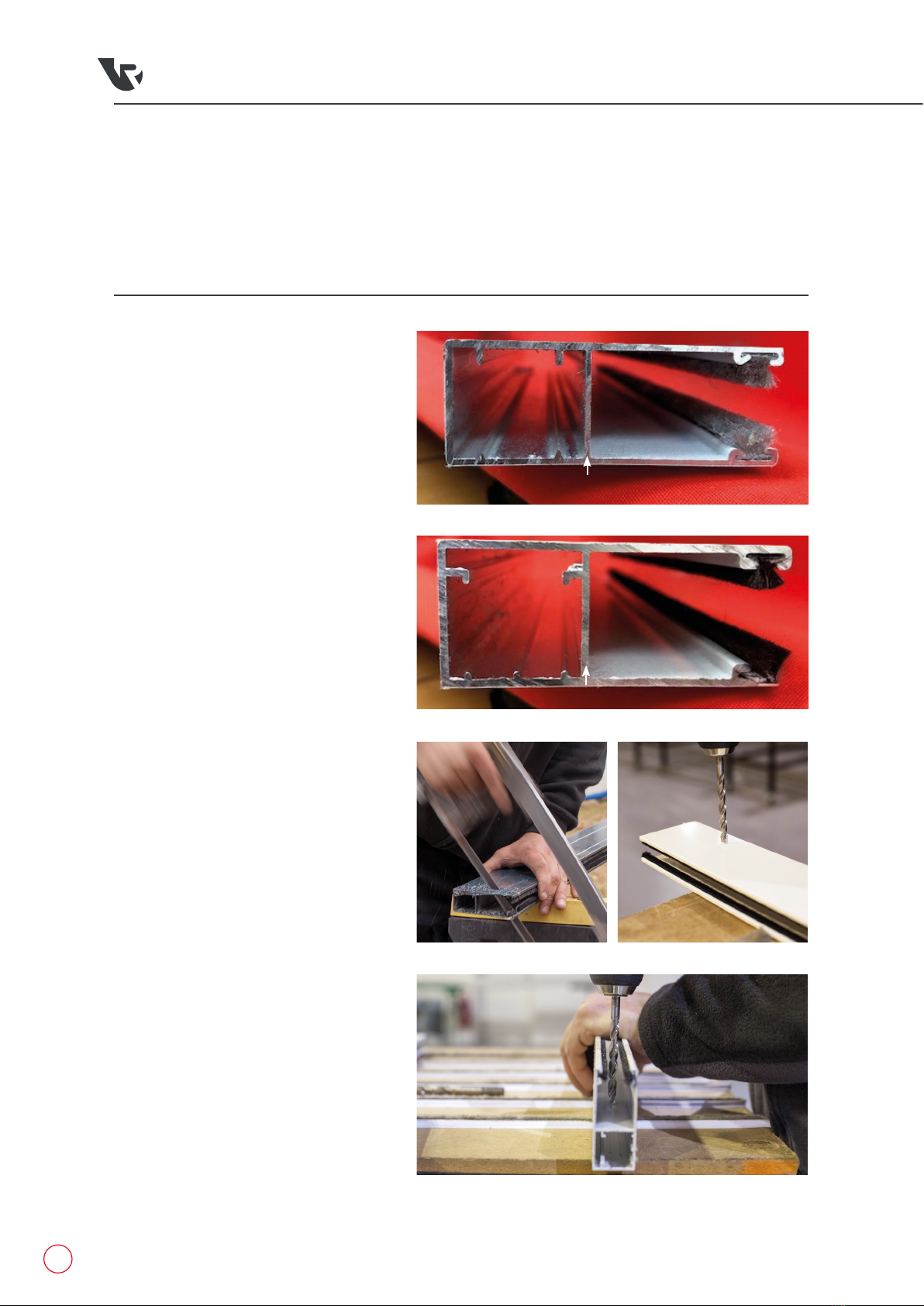
1 We use 2 types of guide runners
whichever is supplied with your kit will
be marked with the letter ‘F’ to indicate
the front, as seen in (fig.3.1 type 1) and
(fig.3.1 type 2). This marked face will
fit against the wall for a standard back
fixing or face out of the opening for a
between fixing (fig.3.5).
2 Your guide runners are supplied
oversize and need to be CUT down
to size, check the lintel is level then
measure from floor to lintel both sides
before referring to (fig3.6) and making
the cuts as necessary (for best results,
install the guide runners so that the cut
end is against the floor).
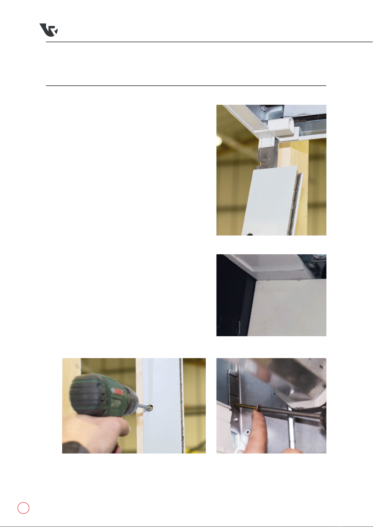
3 Offer both cut guide runners up against
the walls they will be fixed to and mark
the fixing points, either on the flat face
for a behind fixing (fig.3.3) or for a
between fixing in the opening (fig.3.4).
For best results these should be as
follows;
A Top fixing between 50mm to
100mm down from the top of the
guide rail.
B Bottom fixing 50mm to 100mm
up from the floor.
C Marking as many fixings as
necessary but must be at least
two extra fixings. Spread these
evenly between the two already
marked points on the guide
runners so that you have a secure
fix.
D Drill a 7mm hole all the way
through each of the marks
and then drill a 10mm hole to
countersink through the first layer
only so you can get the screw
head through.
fig.3.2
fig.3.4
fig.3.3
(fig.3.1 type 1)
Front Face
(fig.3.1 type 2)
Front Face

8
Rollerdor RD77 Installation Guide, Edition 2022/01
Standard Back Fixing
In Between Fixing
Fig.3.5
LINTEL
ROOF OR
JOISTS
GUIDE
RUNNER GUIDE
RUNNER GUIDE
RUNNER
TOP
ROLL
TOP
ROLL
TOP
ROLL
LINTEL LINTEL
ROOF OR
JOISTS
Behind lintel fixing’ 3Limited opening fixing 2Below lintel fixing 1
300
MM
< >
300
MM
< >
300
MM
< >
ROOF OR
JOISTS
123
FIXING OPTIONS
Below Lintel Fixing:
Cut guide runners to measured height less 310 mm.
Limited Opening Fixing:
Measure from floor to highest point, deduct 310 mm and cut guide runners to size.
Behind Lintel Fixing:
Cut guide runners to measured height.
Fig.3.6

9
Rollerdor RD77 Installation Guide, Edition 2022/01
4. INSTALLING HEADER ASSEMBLY
1 Place your hop ups / step ladders and one guide runner
each side of the opening.
2 With one person each end, lift the header assembly by the
header plate up and then guide the locating stem at each
end into the hollow section of guide runners. If there is
not enough room to simply drop the locating stem in, you
can angle the header plate (fig.4.1). Make sure to insert
the stem fully into the guide runner (fig.4.2).
3 Lift the whole unit flush into place and check that the top
box and guide runners are plumb, level and square.
4 Drill your fixing through the top hole in the guide runners
and secure into place (fig.4.3).
5 Check the case and guide runners are still level and square,
then proceed to drill your remaining fixings, remembering
to check the guide runners are square and plumb aer each
fixing.
6 Once the guide runners are fixed you will need to secure
the top box with 2 fixings each side. This is best done by
drilling through the end flanges of the header plate for a
behind fix, or sideways through the header plate itself if a
between fixing (fig.4.4), PLEASE NOTE: The large cut outs
in header plate are only for use with larger fixings e.g.
shield anchor or coach screw.
7 Check to make sure all fixings have not caused the front
fascia to be pulled in, as this will rub against the slats
causing damage and scratching to the face.
fig.4.4
fig.4.1
fig.4.3
fig.4.2

10
Rollerdor RD77 Installation Guide, Edition 2022/01
5. INSTALLING CONTROL SYSTEM
We supply a varied range of control systems and each one has it's own installation instructions. On the box
your control system came in should be the part number of the system and a QR code for you to scan to take you
straight to the instructions you require from our website.
Alternatively please find below links for every control system we do, clicking on the link for the system you have
on your computer, smart phone or tablet will take you straight to the page on our site where you can find the
instructions, or you can type the link straight into your internet browser.
RD3X2(A)
RD20X2ELL
RD3X2(B)
RD20X2SOM
RD10X2ELL
RD20X2ANSA
RD1X2
https://rollerdor.
net/wp-content/
uploads/2022/01/
Installation-Guide-
RD3X2A-Control-Box-
Type-2.pdf
https://rollerdor.
net/wp-content/
uploads/2022/01/
RD10X2ELL-Control-
Box-Type-9.pdf
https://rollerdor.
net/wp-content/
uploads/2022/01/
RD20X2ELL-Control-
Box-Type-8.pdf
https://rollerdor.
net/wp-content/
uploads/2022/01/
Installation-Guide-
RD20X2ANSA-
Control-Box-Type-7.
pdf
https://rollerdor.
net/wp-content/
uploads/2022/01/
Installation-Guide-
RD3X2B-Control-Box-
Type-2.pdf
https://rollerdor.
net/wp-content/
uploads/2022/01/
RD20X2SOM-Somfy-
Rollixo-Control-Box-
Type-6.pdf
https://rollerdor.
net/wp-content/
uploads/2022/01/
Installation-Guide-
RD1X2-Control-Box-
Type-3.pdf

11
Rollerdor RD77 Installation Guide, Edition 2022/01
6. INSTALLING CURTAIN TO BARREL
(CURTAIN ROLLED SO BASE RAIL IS SEEN)
1 Your locking straps will come attached to the barrel
in no particular place or direction as this is dictated
on installation (fig.6.1).
2 Remove all straps from barrel by removing the
screws from the left collars of every pair and
keeping safe for later, then slide the left collar
across far enough so you have room to remove
the straps (fig.6.2), remove straps and leave in a
safe place then remove all screws from the right
collars and keep safe for later.
3 Press and hold the down button until the barrel
stops on its own, this will be the bottom limit.
Using the manual override handle, wind the barrel
so it rotates in the closing direction until you have
clear access to the screw holes (fig.6.3).
4 Measure 250mm from the head of the motor and
mark the barrel with a pen, measure 250mm from
the safety brake and mark barrel with a pen, then
measure to the middle of the door and mark barrel
with a pen.
5 Attached to the barrel are the White plastic covers,
you have 1 strap and 1 cover per pair of collars
(fig.6.4).
6 Slide the nearest ring to the end of the barrel to
line up with your marks and secure in place with
provided screw, then slide the other ring from the
pair over to this one leaving enough room to be able
to get the strap in (fig.6.3). Spread the remaining
pairs of rings out evenly across the barrel, if there
is an odd number of pairs of rings make sure the
middle pair of rings are one either side of the center
mark.
7 Place a tool box into the opening for the curtain to sit
on to, we recommend placing something so onto
the barrel for this stage to reduce damage to the back
of the curtain. with 1 person each side li the curtain
up and carefully feed it over the barrel into the guides
(fig.6.5) lowering all the way down so it sits on the
tool box.
8 Slide the locking straps on to the top slat of the
curtain trying to make sure they line up with the
pairs of collars you have laid out.
fig.6.1
fig.6.4
fig.6.2
fig.6.3

12
Rollerdor RD77 Installation Guide, Edition 2022/01
fig.6.8
fig.6.5 fig.6.7
fig.6.6
9 Reattach the straps to the barrel;
The plastic covers are provided to add extra protection against marking to the back of the curtain as the
roller door will be rolling on itself, sometimes this can cause marking on the back of the slats. You Do
Not have to install these but we would advise you do. The covers are installed on the locking strap as
in (fig.6.6). Secure each strap into a pair of collars by lining up the metal pin with the hole nearest you
and sliding it into the collar (fig.6.7) then slide the second collar over so the metal pin goes into the hole
leaving a rough 2mm gap either side (fig.6.8), then secure both collars in place with original screws.

13
Rollerdor RD77 Installation Guide, Edition 2022/01
7. INSTALLING CURTAIN TO BARREL
(CURTAIN ROLLED SO TOP SLAT IS SEEN)
1 Your locking straps will come attached to the barrel
in no particular place or direction as this is dictated
on installation (fig.7.2).
2 Remove all straps from barrel by removing the
screws from the left collars of every pair and
keeping safe for later, then slide the left collar
across far enough so you have room to remove
the straps (fig.7.3), remove straps and leave in a
safe place then remove all screws from the right
collars and keep safe for later.
3 Press and hold the down button until the barrel
stops on its own, this will be the bottom limit.
Using the manual override handle, wind the barrel
so it rotates in the closing direction until you have
clear access to the screw holes (fig.7.4).
4 Measure 250mm from the head of the motor and
mark the barrel with a pen, measure 250mm from
the safety brake and mark barrel with a pen, then
measure to the middle of the door and mark barrel
with a pen.
5 Attached to the barrel are the White plastic covers,
you have 1 strap and 1 cover per pair of collars
(fig.7.5).
6 Slide the nearest ring to the end of the barrel to
line up with your marks and secure in place with
provided screw, then slide the other ring from
the pair over to this one leaving enough room to
be able to get the strap in (fig.7.4). Spread the
remaining pairs of rings out evenly across the
barrel, if there is an odd number of pairs of rings
make sure the middle pair of rings are one either
side of the center mark.
7 Slide the locking straps on to the top slat of the
curtain trying to make sure they line up with the pairs
of collars you have laid out. The plastic covers are
provided to add extra protection against marking to
the back of the curtain as the roller door will be rolling
on itself, sometimes this can cause marking on the
back of the slats. You Do Not have to install these but
we would advise you do. The covers are installed on
the locking strap as in (fig.7.6).
fig.7.2
fig.7.3
fig.7.4
fig.7.5

14
Rollerdor RD77 Installation Guide, Edition 2022/01
fig.7.8fig.7.7
fig.7.6
fig.7.5
8 Installing curtain and Reattach the straps to
the barrel; Move a pair of hop ups to each end
making sure you have another room to easily lift
the curtain to meet the barrel, with 1 person each
end lift the curtain up to the barrel and secure the
end straps into a pair of collars by lining up the
metal pin with the hole nearest you and sliding
it into the collar (fig.7.7), then slide the second
collar over so the metal pin goes into the hole
leaving a rough 2mm gap either side (fig.7.8).
9 Carefully Step down from the hop ups and as you
do let the curtain partially unroll in your arms,
let the straps take the majority of the weight so 1
person can move to the middle of the curtain and
hold the remaining weight of the curtain. The other
person will use the hop ups to move to each pair
of collars and attach them as in section 8 but this
time securing all collars with the original screws
provided including the first 2 straps installed in
section 8.

15
Rollerdor RD77 Installation Guide, Edition 2022/01
8. SETTING MOTOR LIMITS
(STANDARD MOTOR)
1 Curtain already in guides: Press and hold the up button on
receiver box so the curtain starts to roll up around the barrel,
keep going until the motor stops or press the stop button if
you get to 300mm (roughly 4 slats) from the top, then remove
item from opening that was used to sit the curtain on.
Curtain in arms: Press and hold the up button on receiver
box so the curtain starts to roll up around the barrel, Making
sure to check the curtain rolls up away from the guide run-
ners, the person with the curtain in their arms needs to let
the door unroll and make sure it doesn’t drop when you get
to the last slats, keep going until the motor stops or press
the stop button if you get to 300mm (roughly 4 slats) from
the top, then use the manual winder to wind the curtain the
last bit until it has passed the guides. Once it has passed the
guides, wind the door back down so 4 slats are in the guides.
2 There are 2 straight line arrows on the head of the motor,
these are to show you the direction that the limit nearest to
it controls, place the plastic wand in to the limit with the
arrow pointing towards the front case (fig.8.1 & fig.8.2)
and turn 10 times in the negative direction, negative (–) and
positive (+) are marked on the head of the motor and are the
same direction for both limits.
3 Press and hold the up button and the curtain will travel to
the top and should stop on its own, if the curtain gets
to 100mm from the top of guide runners (roughly 2 slats)
and hasn’t stopped, then stop the curtain and take
it back down to 300mm from top of guides (roughly 4 slats)
turn again 15 times in the negative direction, take the curtain
up and repeat until the curtain does stop before it gets to
100mm from top.
4 For Somfy Rollixo ONLY: Turn the limit towards the positive
direction (+) and aer each couple of turns, use the buttons
on the control box to close the curtain slightly before opening
it again each time moving a little higher. Keep doing this until
there is one full slat in the guide runners. Take the curtain
down a little and back up to make sure you are happy.
For every other control system: Whilst holding the up
button turn the wand in the positive direction and the
curtain will start to judder up, keep going until there is only
the last slat in the guides. Take the curtain down a little and
back up to make sure you are happy.
fig.8.1
fig.8.3
fig.8.2

16
Rollerdor RD77 Installation Guide, Edition 2022/01
fig.8.4
5 Move the plastic wand in to the other limit with the arrow pointing
towards you and turn 10 times in the negative direction.
6 Press and hold the down button so the curtain closes, it should stop
before it touches the floor if this is not the case take the curtain back up
300mm o the floor and turn again 15 times in the negative direction,
take the curtain back down and repeat until the curtain does stop before
it reaches the floor.
7 For Somfy Rollixo ONLY: Turn the limit towards the positive (+) direction.
Aer each couple of turns, open the curtain slightly and then close it each
time closing a bit further.
For all other control systems: Whilst holding the closed button on the
handset turn the wand in the positive direction and the curtain will start
to judder down.
8 Keep repeating until the curtain is fully compressed and pressure is
applied from the top via the locking strap. The ideal finishing position of
the curtain is to have the top of the guide runner exactly in the middle of
the very top slat (fig.8.4) but no more than 1 full slat above the top of the
guide runner (fig.8.3) if there is more than this you will need to remove
the extra slats.
9 Close the curtain down to make sure it doesn't catch anywhere and the
front case is not bowed in so as to rub on the curtain during operation,
then seal down the sides and along the top case as needed (silicone
sealant is recommended).

17
Rollerdor RD77 Installation Guide, Edition 2022/01
9. SETTING MOTOR LIMITS
(SOMFY MOTOR)
fig.9.2
fig.9.1
1 Your somfy motor comes with a limit cap cover, remove and
keep the cover safe for later (fig.9.1 & 9.2).
2 Using a screw driver press both limits all the way in
so when you release they will click and hold in place
(fig.9.3).
3 Curtain already in guides: Press and hold the up button
on receiver box so the curtain starts to roll up around the
barrel, keep going until there is 1 full slat le in the guide
runner, then remove the tool box from opening that was
used to sit the curtain on.
Curtain in arms: Press and hold the up button on receiver
box so the curtain starts to roll up around the barrel, Making
sure to check the curtain rolls up away from the guide
runners, the person with the curtain in their arms needs to
let the curtain unroll and make sure it doesn’t drop when
you get to the last slats, keep going until the whole curtain
is up passed the top of the guide. Once passed the guides,
wind the curtain down so 2 slats are in the opening, then
press and hold the up button on the receiver box again so
the curtain goes up. Stop the curtain when 1 full slat is le in
the guide runners.
4 Using a screw driver press in and release the coloured limit
for the open / up direction as per diagram (fig.9.5).
5 Run the curtain down until fully compressed and pressure
is applied from the top via the locking strap. The ideal
finishing position of the curtain is to have the top of the
guide runner exactly in the middle of the very top slat
(fig.9.6) but no more than 1 full slat above the top of the
guide runner (fig.9.7) if there is more than this you will
need to remove the extra slats.
6 Using a screw driver press in and release the coloured limit
for the close/down direction as per diagram (fig.9.5).
7 Run the curtain all the way to the top limit to check it stops
in the correct position, then run the curtain all the way to
the bottom limit to check it stops at the correct position
and if happy, replace the cap to cover the limits (fig.9.1). If
the limits are incorrect repeat procedure from start.
8 Close the curtain down to make sure it doesn't catch anywhere
and the front case is not bowed in so as to rub on the curtain
during operation, then seal down the sides and along the top
case as needed (silicone sealant is recommended).
fig.9.3
fig.9.4

18
Rollerdor RD77 Installation Guide, Edition 2022/01
fig.9.7
fig.9.6
fig.9.5

19
Rollerdor RD77 Installation Guide, Edition 2022/01
10. INSTALLATION OF BACK CASE
1 Lift the back case to offer up into place and mark
for winding stem and if needed the wire gland
(fig.10.1).
2 Take down and place on a flat surface (fig.10.2),
then cut out the slots needed (fig.10.3).
3 Clean up any loose or rough edges (fig.10.4).
4 Lift the back case up as close to the winding stem
and gland as possible, hook the back case into
the top lip where the two cases meet (fig.10.5)
and slide across to go all the way to the edge of
the header plate, making sure when it is all the
way over that the whole of the two cases are
slotted together.
5 With the self-tapping screw provided, secure
through the back case into the bottom flange
of the header plate on both sides (fig.10.6).
fig.10.1
fig.10.2
fig.10.3
Completed
fig.10.4
fig.10.6
fig.10.5
Other manuals for RD77
3
Table of contents
Other Rollerdor Garage Door Opener manuals
Popular Garage Door Opener manuals by other brands

Chamberlain
Chamberlain LiftMaster 3280cm 1/2 HP owner's manual

Edison
Edison Autoslide installation manual

Etdoor
Etdoor 600E Installation instructions and user guide

Chamberlain
Chamberlain WD822KD owner's manual

Cardin Elettronica
Cardin Elettronica 311/GL124EBSS instruction manual

BFT
BFT KR92522800003 Installation and user manual

Overhead door
Overhead door 65A Installation and operating instructions

Chamberlain
Chamberlain LM3800TXSA manual

Chamberlain
Chamberlain Smart Garage MYQ-G0401 quick start guide

RIB
RIB AA33694 manual

GOGOGATE
GOGOGATE Garage Door Opener user manual

Automatismos Pujol
Automatismos Pujol Marathon Pro III manual