Tecnoinox FRS35G7 User manual

I
5410.260.00
Fig.2/Abb.2/ .2
Fig.3/Abb.3/ .3
Fig.4/Abb.4/ .4
Fig.5/Abb.5/ .5
Fig.6/Abb.6/ .6
Fig.7/Abb.7/ .7(FRS..)
Fig.7/Abb.7/ .7(FR..-FRV..)

07|2016
DATI TECNICI - TECHNISCHE DATEN - TECHNICAL DATA - DONNEES TECHNIQUES - DATOS TÉCNICOS - ТЕХНИЧЕСКИЕ ХАРАКТЕРИСТИКИ
5410.260.00
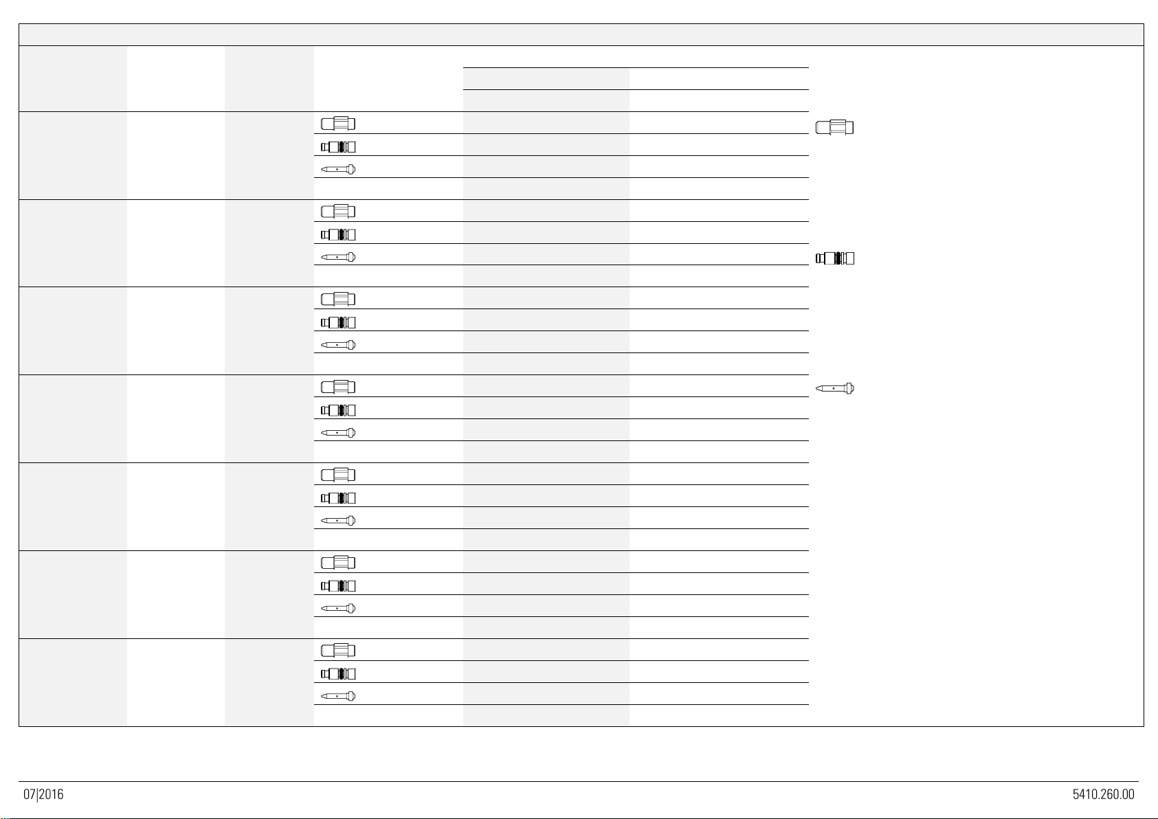
TABELLA UGELLI - DÜSENTABELLE - NOZZLE TABLE - TABLEAU DES INJECTEURS - TABLA DE LOS INYECTORES - ТАБЛИЦА ФОРСУНОК
CATEGORIA
Kat.; Cat., Кат.
P [mbar]
P [мбар]
GAS
Газ
Dim. / Разм.
1/100 mm
Bruciatore - brenner - burner - brûleur –quemadores - горелки
Brennerdüse
Burner nozzle
Injecteur du brûleur
Boquillas de los
quemadores.
Форсунка горелки
Kleinstellschraube
Minimum adjusing screw
Vis de réglage minimum
Tornillo de regulación del
mìnimo
Винт мин.регулировки
Zündbrennerdüse
Pilot burner nozzle
Injecteur de la veilleuse
Boquillas del piloto.
Форсунка зап.горелки
H
Aria primaria
Primärluft Abstand
Primary air
Air primaire distance
Aire primario distance
Первичный воздух
FRS35G7
FR43FG7
FRS70G7
FR83FG7
FR48FG7
11.5 kW, кВт
12 kW, кВт
23 kW, кВт
24 kW, кВт
6 + 6 kW, кВт
2E
2E+
2H
20
G20
MAX, макс.
2 × 195
4 × 195
2 × 195
MIN, мин.
-
-
-
PILOTA, Зап.устр.
45
2 × 45
2 × 35
H [mm]
12
12
12
3+
3B/P+
28-30/37
G30/G31
MAX, макс.
2 × 125
4 × 125
2 × 125
MIN, мин.
-
-
-
PILOTA, Зап.устр.
35
2 × 35
2 × 20
H [mm]
MAX, макс.
MAX, макс.
MAX, макс.
3B/P
37
G30/G31
MAX, макс.
2 x 115
4 × 115
2 × 115
MIN, мин.
-
-
-
PILOTA, Зап.устр.
35
2 × 35
2 × 20
H [mm]
MAX, макс.
MAX, макс.
MAX, макс.
3B/P
50
G30/G31
MAX, макс.
2 × 110
4 × 110
2 × 110
MIN, мин.
-
-
-
PILOTA, Зап.устр.
35
2 × 35
2 × 20
H [mm]
MAX, макс.
MAX, макс.
MAX, макс.
2LL
20
G25
MAX, макс.
2 × 220
4 × 220
2 × 220
MIN, мин.
-
-
-
PILOTA, Зап.устр.
45
2 × 45
2 × 35
H [mm]
12
12
12
2L
25
G25
MAX, макс.
2 × 205
4 × 205
2 ×205
MIN, мин.
-
-
-
PILOTA, Зап.устр.
45
2 × 45
2 × 35
H [mm]
12
12
12
2S
25
G25.1
MAX, макс.
2 × 210
4 × 210
2 × 210
MIN, мин.
-
-
-
PILOTA, Зап.устр.
45
2 × 45
2 × 35
H [mm]
12
12
12
DATI TECNICI - TECHNISCHE DATEN - TECHNICAL DATA - DONNEES TECHNIQUES - DATOS TÉCNICOS - ТЕХНИЧЕСКИЕ ХАРАКТЕРИСТИКИ
TABELLA UGELLI - DÜSENTABELLE - NOZZLE TABLE - TABLEAU DES INJECTEURS - TABLA DE LOS INYECTORES - ТАБЛИЦА ФОРСУНОК
CATEGORIA
Kat.; Cat., Кат.
P [mbar]
P [мбар]
GAS
Газ.
Dim / Разм.
1/100 mm
Bruciatore - brenner - burner - brûleur –quemadores - горелки
Brennerdüse
Burner nozzle
Injecteur du brûleur
Boquillas de los quemadores
Форсунка горелки
Kleinstellschraube
Minimum adjusing screw
Vis de réglage minimum
Tornillo de regulación del mìnimo
Винт мин.регулировки
Zündbrennerdüse
Pilot burner nozzle
Injecteur de la veilleuse
Boquillas del piloto
Форсунка зап.горелки
H
Aria primaria
Primärluft Abstand
Primary air
Air primaire distance
Aire primario distance
Первичный воздух
FRV43FG7
FRV83FG7
11.5 kW, кВт
23 kW, кВт
2E
2E+
2H
20
G20
MAX, макс.
2 × 190
4 × 190
MIN, мин.
-
-
PILOTA, Зап.устр.
45
2 × 45
H [mm]
8
8
3+
3B/P+
(10.5 kW, кВт)
28-30/37
G30/G31
MAX, макс.
2 × 115
4 × 115
MIN, мин.
-
-
PILOTA, Зап.устр.
35
2 × 35
H [mm]
15
15
3B/P
(10.5 kW, кВт)
37
G30/G31
MAX, макс.
2 x 110
4 x 110
MIN, мин.
-
-
PILOTA, Зап.устр.
35
2 × 35
H [mm]
15
15
3B/P
(11.5 kW, кВт)
50
G30/G31
MAX, макс.
2 × 110
4 × 110
MIN, мин.
-
-
PILOTA, Зап.устр.
35
2 × 35
H [mm]
5
5
2LL
20
G25
MAX, макс.
2 × 215
4 × 215
MIN, мин.
-
-
PILOTA, Зап.устр.
45
2 × 45
H [mm]
5
5
2L
25
G25
MAX, макс.
2 × 205
4 × 205
MIN, мин.
-
-
PILOTA, Зап.устр.
45
2 × 45
H [mm]
5
5
2S
25
G25.1
MAX, макс.
2 × 205
4 × 205
MIN, мин.
-
-
PILOTA, Зап.устр.
45
2 × 45
H [mm]
5
5
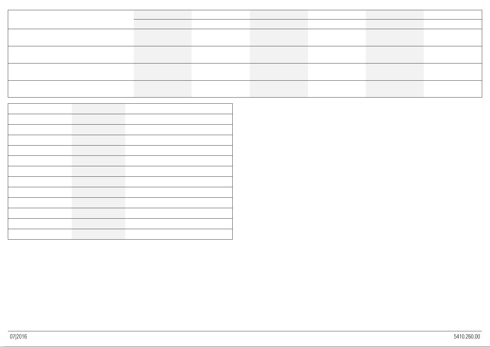
DATI TECNICI - TECHNISCHE DATEN - TECHNICAL DATA - DONNEES TECHNIQUES - DATOS TÉCNICOS - ТЕХНИЧЕСКИЕ ХАРАКТЕРИСТИКИ
Consumo - Gasverbrauch - Gas consumption -
Consommation du gaz - Consumo de gas - Расход газа
FRS35G7 - FR43FG7
FR48FG7
FRS70G7
FR83FG7
FRV43FG7
FRV83FG7
11.5 kW, кВт
12 kW, кВт
23 kW, кВт
24 kW, кВт
11.5 kW, кВт
23 kW, кВт
Metano, Метан (G20)
(Hi = 9.45 kWh/m3) m3/h - Hi = 9.45 кВт ч/м3) м3/ч
1.22
1.27
2.44
2.54
1.16 (11 kW, кВт)
2.32 (11 + 11 kW, кВт)
Metano, Метан (G25)-(G25.1)
(Hi = 8.13 kWh/m3) m3/h - (Hi = 8.13 кВт ч/м3) м3/ч
1.41
1.48
2.83
2.95
1.35 (11 kW, кВт)
2.70 (11 + 11 kW, кВт)
GPL, GPL (G30)
(Hi = 12.68 kWh/kg) kg/h - (Hi = 12.68 кВт ч/кг) кг/ч
0.91
0.95
1.82
1.89
0.83 (10.5 kW, кВт)
1.66 (10.5 + 10.5 kW, кВт)
GPL, GPL (G30) 50 mbar
(Hi = 12.68 kWh/kg) kg/h - (Hi = 12.68 кВт ч/кг) кг/ч
0.91
0.95
1.82
1.89
0.91
1.82
Cat. - Kat. - Кат.
P [mbar] / P [мбар]
Paese - land - country - pays –país - cтрана
I2E
20
LU,PL
I2E+
20/25
BE
I3+
28-30/37
BE,LU
I3B/P
28-30
NL,NO,CY,MT
II2E+3+
20/25, 28-30/37
BE,FR
II2ELL3B/P
20, 50
DE
II2H3+
20, 28-30/37
ES,GB,GR,IE,IT,PT,SK
II2H3B/P
20, 28-30
BG,DK,EE,FI,LV,LT,CZ,SE,SI
II2H3B/P
20, 50
AT,CH
II2L3B/P
25, 28-30
NL
II2S3B/P
25, 30
HU
II2S3B/P
25, 50
HU
IT - 1
5410.260.00
Parte 1
Installazione
FRIGGITRICI GAS FREESTANDING
Avvertenze Generali
L'apparecchio descritto nel presente libretto è costruito nel rispetto
dei requisiti delle norme UNI EN 203 eUNI EN 437.
Quest’apparecchiatura è concepita unicamente per la cottura degli
alimenti, ogni altro tipo d’impiego è da ritenersi improprio; è destinata
solo ad uso professionale da parte di personale qualificato.
L'apparecchio deve essere utilizzato esclusivamente sotto
sorveglianza. Si consiglia inoltre, un controllo annuale da eseguirsi a
cura di professionisti qualificati.
Disattivare l'apparecchiatura in caso di guasto o cattivo
funzionamento.
Si consiglia di installare l’apparecchio sotto ad una cappa aspirante per l’evacuazione dei vapori prodotti durante la cottura.
Prestare attenzione durante il funzionamento poiché la vasca e le superfici di cottura sono molto calde.
L'allacciamento, l'installazione e la manutenzione dell'apparecchiatura devono essere eseguiti a cura di personale qualificato
secondo le norme e le prescrizioni vigenti nel paese, in conformità alle presenti istruzioni.
Caratteristiche dell’apparecchio
Il presente libretto d’istruzioni per l’installazione ed uso si riferisce ai
friggitrice gas della categoria II2H3+.
La targhetta matricola in poliestere autoadesivo si trova dietro
al pannello portacomandi (all'interno dell'apparecchio).
Essa contiene i seguenti dati:
Modello:
FRS35G7
FRS70G7
Numero di serie:
xxxxxx
Categoria:
II2H3+
Anno di fabbricazione:
xxxx
Portata termica nominale:
11.5 kW
23 kW
Tipo di costruzione:
A1
A1;B21
Base di prova:
UNI EN 203-1
Pressione di collegamento:
G30
G20
28-30/37 mbar
20 mbar
Consumo:
G30
G20
0.91
1.22
Kg/h
m3/h
1.82
2.44
Kg/h
m3/h
La targhetta supplementare è in poliestere autoadesivo ed è
applicata vicino alla targhetta matricola, essa contiene tutte le
informazioni sulla predisposizione dell’apparecchio. L’apparecchio
FRS35G è dotato di due bruciatori e una rampa per il collegamento
del gas. L'apparecchio FRS70G è dotato di quattro bruciatori e due
rampe per il collegamento del gas. L’attacco per il collegamento alla
rete del gas “G” (fig.1) corrisponde alle prescrizioni ISO 7/1 e ISO
228/1 (DK) con attacco ø ½”, esso è situato nella parte inferiore della
macchina.
La struttura dell’apparecchio è d’acciaio inox ed i bruciatori sono
d’acciaio. Tutti i modelli inoltre sono dotati di piedini regolabili in
altezza.
La conduttura principale del gas è d’acciaio zincato. Le condutture di
collegamento dal rubinetto al bruciatore sono di rame.
ATTENZIONE!
Interporre tra l'apparecchio e la rete di distribuzione un rubinetto
d’intercettazione.
Collegamento alla rete
Prima di procedere all’installazione dell’apparecchiatura
è indispensabile farsi rilasciare dall’ente erogatore del
gas il nullaosta all’installazione, confrontare poi i dati
relativi alle predisposizioni dell’apparecchiatura
(targhetta caratteristiche) con l’erogazione in loco.
Togliere l'imballo dall'apparecchiatura, rimuovere la pellicola
protettiva e, se necessario eliminare le tracce di colla con l'ausilio di
un idoneo solvente. Si raccomanda di smaltire l'imballo secondo le
norme vigenti (per maggiori dettagli fare riferimento al capitolo
"ECOLOGIA E AMBIENTE”).
Prima di collegare l’apparecchio alla rete del gas, controllare sulla
targhetta matricola se l’apparecchio è predisposto e collaudato per il
tipo di gas e la pressione disponibile.
Qualora tipo di gas o pressione riportati in targhetta non
corrispondano al tipo di gas e alla pressione disponibile, consultare il
paragrafo “TRASFORMAZIONE ED ADATTAMENTO”.
Il collegamento alla rete di distribuzione del gas deve avvenire con
tubi metallici di diametro adeguato e con interposizione di un
rubinetto d’intercettazione omologato.
Se vengono impiegati tubi flessibili, questi devono essere di acciaio
inossidabile secondo le norme vigenti.
▪Norma di sicurezza UNI-CIG 8723, legge nr.46 del 5 marzo 1990
e circolare nr.68.
▪Norme regionali e/o locali quali regolamento edilizio.
▪Norme antinfortunistiche vigenti.
▪Prescrizioni antincendio.
▪Relative norme CEI.
Si consiglia d’installare l'apparecchio in un ambiente ben areato, o
sotto una cappa aspirante per l'evacuazione dei fumi o vapori
prodotti durante il ciclo di cottura.
L’apparecchiatura è inoltre dotata di morsetto equipotenziale
posizionato nella parte posteriore "N"(fig.1).
L’apparecchio può essere installato da solo o in batteria.

IT - 2
5410.260.00
Rispettare una distanza minima di 80mm tra l'apparecchiatura ed
eventuali pareti in materiale infiammabile, divisori, mobili da cucina o
da apparecchiature adiacenti.
Le superfici a contatto dovranno essere rivestiti in materiale isolante
termico di tipo non combustibile.
ATTENZIONE !
Nel modello FSR35G7 è necessario fissare l’apparecchiatura a
pavimento tramite l’apposita staffa (rif. F fig.2).
Ad installazione avvenuta procedere al controllo di tenuta dei
raccordi. Per individuare eventuali perdite si consiglia l’utilizzo di
prodotti a base schiumosa non corrosiva, tipo spray cerca fughe.
Durante la prova di tenuta non usare fiamme libere!
Il costruttore non si assume nessun impegno di garanzia per danni che accadessero a causa dell’inosservanza delle istruzioni
d’installazione d’uso, o d’utilizzo improprio. Non si assume inoltre alcun impegno di garanzia per un allacciamento non
eseguito in conformità alle norme vigenti e le prescrizioni antincendio.
Evacuazione dei fumi di combustione
Non è necessario collegare ad un camino le apparecchiature FSR35G7 (tipo A1) e FSR70G7 (tipo A1,B21).
Controllo della pressione
La pressione di rete dovrà rispettare quanto segue.
GPL
AMMESSO
Tra 20/25 e 35/45 mbar
NON AMMESSO
Inf. a 20/25 sup. a 35/40 mbar
METANO
H
AMMESSO
Tra 17 e 25 mbar
NON AMMESSO
Inf. a 17 e sup. di 25 mbar
Qualora la pressione di rete sul posto d’installazione non sia come
sopra riportato, avvisare l’ente preposto alla distribuzione e non
procedere alla messa in funzione prima che la causa non sia stata
individuata ed eliminata.
La pressione di rete è rilevabile con un manometro ad U (definizione
min. 0.1mbar), collegabile alla presa di pressione dietro il cruscotto
“H” (fig.6).
1. Rimuovere il cruscotto portacomandi.
2. Togliere la vite e rondella di tenuta dalla presa di pressione e
collegare il manometro.
3. Mettere in funzione l’apparecchio secondo le istruzioni accluse
e controllare se la pressione riscontrata rientra nel campo delle
pressioni ammesse.
4. Scollegare il manometro e riposizionare la vite e la rondella di
tenuta nella presa di pressione.
5. Serrare la vite e rimontare il cruscotto e le manopole.

IT - 3
5410.260.00
Parte 2
Trasformazione ed adattamento
Per la trasformazione da un tipo di gas ad un altro, per es. da
metano a GPL, si rende necessaria la sostituzione degli ugelli del
bruciatore principale, del by-pass e del pilota. Tutti gli ugelli sono
contrassegnati da un numero che indica il diametro in 1/100 e forniti
in dotazione in un sacchetto.
Dopo ogni trasformazione o adattamento, sottoporre l’apparecchio
ad una prova delle funzioni e aggiornare la targhetta supplementare
in base alla trasformazione o adattamento effettuato.
Si raccomanda che tutti i lavori relativi all’allacciamento, all’installazione ed alla manutenzione dell’apparecchio siano eseguiti
esclusivamente da personale qualificato ed in osservanza di tutte le relative prescrizioni!
Sostituzione ugelli e regolazione dell’aria
BRUCIATORE:
Aprire le porte ed individuare gli ugelli (fig.5).
Sostituire gli ugelli “U” (fig.5) con quelli adatti al nuovo tipo di gas
vedi tabella ugelli - T1 nella sezione Dati tecnici.
REGOLAZIONE ARIA:
Svitare la vite di fissaggio della boccola regolazione aria primaria.
Spostare la boccola fino alla distanza “H” (fig.7) indicata nella tabella
ugelli T1 sezione Dati tecnici.
Bloccare la boccola avvitando la vite di fissaggio.
PILOTA:
Svitare e togliere il dado di chiusura.
Sostituire l'ugello del pilota “D” (fig.3) in base alle indicazioni della
tabella ugelli - T1.
Rimontare il dado di chiusura.
IT - 4
5410.260.00
Parte 3
Uso
Riempimento della vasca
Controllare che il rubinetto di scarico del olio “C” (fig.2) posto
internamente all'apparecchio sia in posizione chiusa.
Introdurre il grasso, prima sciolto a parte, o l’olio e controllare che
non superi il livello massimo; ogni vasca può contenere al massimo
14 litri.
Non utilizzare mai l’apparecchio a secco.
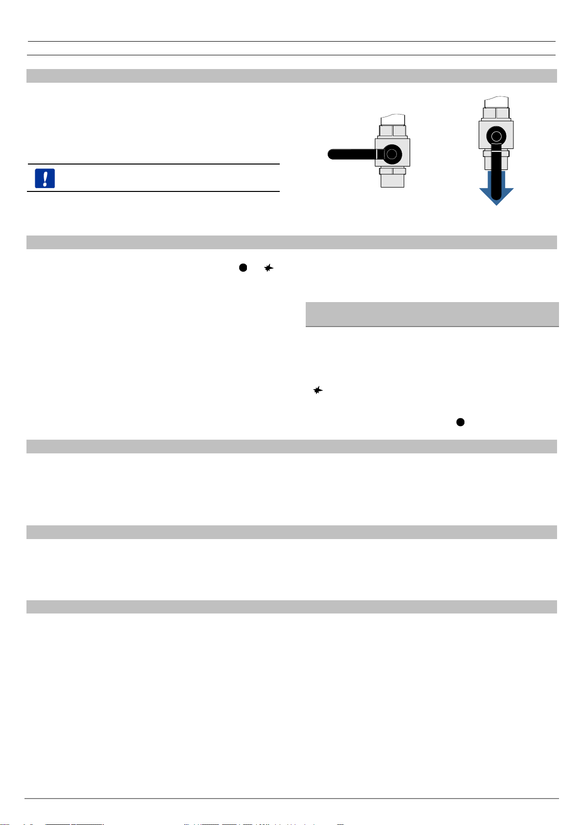
CHIUSA
APERTA
Accensione del bruciatore e dell’apparecchio
Premere e ruotare la manopola “A” (fig.4) dalla posizione “ ” a "
" mantenendola premuta.
Contemporaneamente azionare ripetutamente il pulsante
d'accensione “B” (fig.4) fino ad innescare la fiamma pilota.
Ad accensione avvenuta mantenere la manopola premuta per circa
10 secondi (contare fino a 20); si da modo così alla termocoppia di
scaldarsi e quindi di tenere aperta la valvola di sicurezza.
Nota: qualora il dispositivo piezoelettrico fosse inutilizzabile,
l'accensione può avvenire anche manualmente con un fiammifero
oppure con un accenditore gas.
Per ottenere l'accensione del bruciatore principale, si ruota
ulteriormente la manopola fino alla posizione desiderata
Pos.
1
2
3
4
5
6
7
C°
85
100
115
130
155
175
195
SPEGNIMENTO BRUCIATORI:
Ruotare la manopola dalla posizione in cui si trova fino alla posizione
““.
SPEGNIMENTO DELL'APPARECCHIO:
Ruotare la manopola fino alla posizione “ ”.
Consigli per la cottura
▪Gli alimenti da friggere non devono essere troppo bagnati. La
massa da friggere non deve superare i 2 kg per carico.
▪Durante l'utilizzo dell'apparecchio tenere il coperchio a portata
di mano.
▪Sostituire spesso l'olio di frittura per evitare il pericolo
d’incendio.
Svuotamento della vasca
Assicurarsi che la macchina sia spenta e l’olio a temperatura
ambiente. Per lo svuotamento della vasca utilizzare il contenitore “V”
(fig.2) in dotazione.
Assicurarsi che il contenitore sia posizionato in modo corretto sotto il
rubinetto di scarico, ruotare lentamente la manopola della valvola “C”
(fig.2). Qualora l'olio o il grasso venga riutilizzato filtrarlo.
Termostato di sicurezza
In caso di surriscaldamento, a causa d’utilizzo non conforme
dell'apparecchio o per difetto di qualche componente, interviene il
termostato di sicurezza “E” (fig.2); quest'ultimo intercetta
automaticamente l'erogazione del gas ai bruciatori. Quando
interviene questo dispositivo, chiudere il rubinetto del gas posto a
monte dell’apparecchiatura e avvisare il servizio assistenza.

IT - 5
5410.260.00
Comportamento in caso di prolungata inattività
Chiudere il rubinetto d’intercettazione gas installato a monte.
Effettuare la pulizia con acqua saponata, risciacquare, asciugare con
cura e stendere un leggero strato d’olio di vaselina.
Comportamento in caso di guasti
I guasti non sempre dipendono dalla qualità dei componenti, che nel
nostro caso sono d’ottima fattura, essi possono essere causati anche
da sbalzi di tensione, da polvere o sporco che penetra nei
componenti funzionali.
In qualsiasi caso in cui si sospetta un funzionamento anormale
chiudere il rubinetto del gas, avvisare il servizio d’assistenza
autorizzato.
Non improvvisarsi manutentori, la manomissione dell'apparecchio implica il decadimento della garanzia.
Controllo del funzionamento
Prima di consegnare l’apparecchio all’utilizzatore eseguire i seguenti
controlli:
PORTATA TERMICA
Controllare se il tipo e gruppo di gas in utenza corrisponde a quanto
riportato sulla targhetta. In caso contrario procedere ad una
trasformazione o ad un adattamento; in questo caso consultare il
paragrafo “Trasformazione ed adattamento”.
Controllare se sono installati gli ugelli corretti.
Allo scopo consultare la tabella ugelli e controllare, la corrispondenza
con quelli montati sull’apparecchiatura.
Per un controllo supplementare della portata, si può verificare il
consumo di gas con il metodo volumetrico: mettere in funzione il
bruciatore, dopo ca. 10 minuti (condizione a regime) controllare se il
flusso di gas (in m3/h oppure in kg/h) rilevato corrisponde a quanto
riportato nella tabella ugelli.
ASPETTO DI FIAMMA E FLUSSO DELL'ARIA PRIMARIA
Utilizzare il foro d’ispezione “I” (fig.2) per controllare la fiamma.
La fiamma deve essere di colore blu, non deve evidenziare punte
gialle e deve essere stabile alla base.
L’aspetto della fiamma con colore tendente al giallo evidenzia
un’errata regolazione dell’aria primaria. Se l’aria primaria è in
eccesso, la fiamma è corta e tende a staccarsi dal bruciatore.
Il controllo dell’aspetto della fiamma deve essere effettuato anche
dopo ca. 15 minuti di funzionamento alla potenza massima. La
fiamma deve restare stabile anche dopo un passaggio veloce da
minimo a massimo.
ISTRUZIONI PER L'UTENTE
L’utente deve essere debitamente istruito sull’impiego corretto, sulle
funzioni e sull’uso dell’apparecchio. Si fa presente che modifiche
all’ambiente d’installazione, che possono influenzare l’apporto d’aria
comburente, comportano un nuovo controllo del funzionamento
dell’apparecchio. Al termine dei controlli sottoporre l’apparecchio ad
una prova di tenuta.
Sostituzione di parti
La sostituzione di parti difettose, deve essere eseguita esclusivamente da personale abilitato. Prima di iniziare qualsivoglia lavoro
scollegare l’apparecchio dalla rete di distribuzione del gas.
I pezzi di ricambio sono da richiedere esclusivamente al costruttore o ad un rivenditore autorizzato.

IT - 6
5410.260.00
Parte 4
Manutenzione e pulizia
Pulizia e cura
PULIZIA:
ATTENZIONE: La pulizia deve essere effettuata solamente ad
apparecchio raffreddato.
Si ricorda, che la pulizia è molto importante per il buon
funzionamento e per una lunga durata dell’apparecchio.
Le parti rimovibili sono da lavare separatamente con acqua calda e
detergente e da sciacquare poi con acqua corrente.
Per la pulizia delle parti d’acciaio inossidabile non sono da impiegare
sostanze aggressive o comunque detergenti abrasivi. L’uso di
paglietta di ferro è sconsigliato poiché può provocare formazione di
ruggine. Per lo stesso motivo evitare il contatto con materiali ferrosi.
Durante la pulizia evitare anche l’utilizzo di carta o tela vetrata; in
sostituzione e solo per casi particolari si può usare pietra pomice in
polvere; nel caso di sporco tenace si consiglia l’ausilio di spugne (p.
es. Scotch). In caso di sporco tenace può essere usato anche dello
spray per forni e grill comunemente reperibili. In questo caso
osservare attentamente le avvertenze del produttore.
Allo scopo di ridurre l'emissione in ambiente di sostanze inquinanti, si
consiglia di pulire l'apparecchiatura con prodotti aventi una
biodegradabilità superiore al 90%.
Avvertenze per la sicurezza
SI RICORDA CHE L’APPARECCHIO:
▪Dev’essere utilizzato solamente sotto sorveglianza!
▪Durante l’uso, le superfici diventano molto calde e pertanto si
raccomanda particolare prudenza!
▪E’ destinato ad uso professionale e pertanto solo personale
qualificato può utilizzarlo!
▪L’installazione nonché un’eventuale trasformazione o un
adattamento ad un altro tipo di gas, possono essere eseguite
secondo le prescrizioni di legge vigenti esclusivamente da
personale qualificato ed autorizzato.
▪Almeno una volta l’anno va sottoposto ad un controllo, a cura di
personale qualificato.
▪E tutte le parti dell’apparecchiatura, che durante l'uso vanno in
contatto con il cibo, sono da pulire regolarmente seguendo il
capitolo "Pulizia e cura".
INCENDIO:
Nel caso d’incendio chiudere immediatamente il rubinetto
d’intercettazione del gas, coprire la vasca con il coperchio in
dotazione ed utilizzare un estintore adeguato.
IT - 7
Il costruttore declina ogni responsabilità nel caso di danni provocati da errata installazione, impropria manutenzione ed inosservanza
delle prescrizioni di sicurezza.
GB / IE - 1
5410.260.00
Part 1
Installation
FREESTANDING GAS FRYERS
General Instructions
The appliance described in this manual has been built to meet UNI
EN 203 and UNI EN 437 standards.
This appliance has been designed exclusively for cooking food, any
other use is considered improper. It should only be used by qualified
personnel in professional kitchens.
The unit must never be left unattended when it is being used! The
appliance should be checked once a year by a qualified technician.
Switch the appliance off in the case of a failure or malfunction.
The appliance should be installed under an extractor hood for removing any cooking fumes.
Care must be taken when using the appliance because the cooking surfaces are very hot.
The appliance must be installed, connected and serviced properly by qualified personnel according to the regulations and
directives in force in the country where it is installed, as well as the instructions in this manual.
Unit characteristics
This instruction manual refers to the installation and use of the
Category II2H3+ gas fryers.
The self-adhesive polyester data plate is behind the control
panel (inside the appliance).
It contains the following information:
Model
FRS35G7
FRS70G7
Serial number:
xxxxxx
Category:
II2H3+
Year of construction:
XXXX
Nominal thermal capacity:
11.5 kW
23 kW
Type of construction:
A1
A1;B21
Test base:
UNI EN 203-1
Connection pressure:
G30
G20
28-30/37 mbar
20 mbar
Consumption:
G30
G20
0.91
1.22
Kg/h
m3/h
1.82
2.44
Kg/h
m3/h
The supplementary plate is also made of self-adhesive polyester and
is affixed near the data plate; it contains all information regarding the
appliance. The FRS 35G appliance has two burners and a fitting for
gas connection. The FRS 70G appliance has four burners and two
gas connection fittings. The "G" gas distribution network fitting
(fig.1) meets ISO 7/1 and ISO 228/1 (DK) standards with a ø ½”
connection, situated at the back of the machine.
The structure of the appliance is made of stainless steel and the
burners are made of steel. All models have adjustable feet.
The main gas pipe is made of galvanised steel. The pipes between
the tap and burner are made of copper.
WARNING!
Install a shut-off cock in the line between the appliance and the gas
distribution network.
Connection to the distribution network
Before you install the appliance make sure that the
gas company has authorised the installation,
compare the data relevant of the appliance (data
plate) with the local supply.
Remove the packaging from the appliance as well as the protective
plastic sheet, and, if necessary, remove traces of glue with a suitable
solvent. To dispose of the packaging, follow local directives (for more
details refer to the chapter “ECOLOGY AND THE ENVIRONMENT”.
Prior to connecting the appliance to the gas network, check the data
plate to see if it has been set and tested for the type of gas and
pressure supplied.
If the gas type or pressure indicated on the data plate is not the
same as that supplied, please refer to the paragraph “CONVERSION
AND ADAPTATION”.
Connect the appliance to the gas distribution network using metal
pipes with a suitable diameter; install a homologated on/off cock
between the appliance and the distribution network.
If flexible pipes are used they must be made of stainless steel
according to the standards in force.
▪UNI-CIG 8723 safety standard, Act n.46 of the 5th of March 1990
and circular n.68.
▪Regional and/or local regulations, such as building codes;
▪Accident prevention regulations in force;
▪Fire prevention regulations;
▪Applicable I.E.C. regulations.
We recommend installing the appliance in a well-ventilated
environment, or under an extraction hood to remove the fumes or
vapours produced during the cooking cycle.
The appliance has an equipotential earth terminal “N”(fig.1)at the
back.
The appliance can be installed alone or in line.
Respect a minimum distance of 80mm between the appliance and
any walls made of flammable material, partitions, kitchen furniture or
nearby equipment.
The contact surfaces must be covered with non-combustible heat
insulating material.

GB / IE - 2
5410.260.00
WARNING!
The FSR35G7 model must be fixed to the floor with the relevant
bracket (Ref. F fig.2).
After installing the appliance check for any leaks in the fittings. Use
non-corrosive foam products, such as leak detection sprays, to look
for any leaks.
When checking for leaks do not use naked flames!
The manufacturer shall not be held responsible and the guarantee is void in the case of damage caused by negligence in
following the operating and installation instructions or by improper use. The guarantee is void in the case of connections which
have been made in a way which doesn't meet the current standards and fire-fighting regulations.
Evacuation of burnt gases
The FSR35G7 (type A1) and FSR70G7 (type A1,B21) equipment doesn't need to be connected to a flue.
Checking the pressure
The distribution network pressure must meet the following
specifications:
LPG
ALLOWED
From 20/25 to 35/45 mbar
NOT ALLOWED
Below 20/25 above 35/40 mbar
METHANE
H
ALLOWED
From 17 to 25 mbar
NOT ALLOWED
Below 17 above 25 mbar
If the gas distribution network pressure on the installation site doesn't
meet the above values, inform the gas board and do not turn the unit
on until the cause and a solution have been found.
The distribution network pressure can be taken with a U manometer
(min. definition 0.1 mbar), connected to the pressure outlet behind
control panel “H” (fig.6).
1. Remove the control panel.
2. Remove the screw and sealing washer from the pressure outlet
and connect the manometer.
3. Turn the unit on following the enclosed instructions and check
that the pressure is within the permitted pressure range.
4. Disconnect the manometer and replace the screw and the
sealing washer in the pressure outlet.
5. Tighten the screw and reassemble the panel and the knobs.

GB / IE - 3
5410.260.00
Part 2
Transformation and adaptation
To convert the appliance to another type of gas, e.g. from natural gas
to LPG, the nozzles of the main burner, by-pass and pilot light have
to be changed. All the nozzles are marked with a number that
indicates the diameter in 1/100 and are supplied in a bag.
After each conversion or adaptation, the unit must undergo an
operating test and the supplementary plate must be updated
according to the conversion or adaptation carried out.
Connections to the distribution network, installation, and maintenance of the appliance must only be carried out by qualified
technicians only, in observance of all applicable regulations!
Replacing the nozzles and adjusting the air
BURNER:
Open the doors and find the nozzles (fig.5).
Replace the nozzles “U” (fig.5) with suitable ones for the new type of
gas see nozzles table - T1 in the section Specifications.
ADJUSTING THE AIR:
Unscrew the screw holding the primary air adjustment bush. Move
the bush to the distance “H” (fig.7) indicated in the nozzles table T1
in the section Specifications.
Block the bush by tightening its fixing screw.
PILOT LIGHT:
Unscrew and remove the closing nut.
Replace pilot nozzle “D” (fig.3) on the basis of the indications in the
nozzles table - T1.
Reassemble the closing nut.

GB / IE - 4
5410.260.00
Part 3
Use
Filling the tub
Check that the oil drain valve “C” (fig.2) inside the appliance, is
closed.
Introduce the fat, that has previously been melted in another
recipient, or the oil and check that they do not go over the maximum
level; each tub can contain a maximum of 14 litres.
WARNING!
Do not use the appliance without water.
CLOSED
OPEN
Turning the burner of the appliance on
Press and turn knob “A” (fig.4) from position “ ” to " " keeping it
pressed in.
At the same time press ignition button “B” (fig.4) repeatedly to light
the pilot light.
After the flame has lit, hold the knob down for roughly 10 seconds
(count to 20); so the thermocouple heats up and keeps the safety
valve open.
Note: if the piezoelectric device cannot be used, you can light the
flame by hand using a match or a gas lighter.
To light the main burner, turn the knob again until it reaches the
desired position.
Pos.
1
2
3
4
5
6
7
°C
85
100
115
130
155
175
195
TURNING THE BURNERS OFF:
Turn the knob from the position it is in to the ““position.
TURNING THE APPLIANCE OFF
Turn the knob to the “ “ position.
Recommendations for cooking
▪The food to fry mustn't be too wet. The quantity to be fried must
not exceed 2kg. in weight each load.
▪Whilst using the appliance, keep the lid within reach.
▪Replace the frying oil frequently to avoid the risk of fire.
Emptying the tub
Make sure the machine is turned off and the oil is at room
temperature. To empty the tub, use the “V” recipient (fig.2) supplied.
Make sure the recipient is positioned correctly under the drain valve,
turn the handle of valve “C” (fig.2) slowly. Filter the oil or fat if you
wish to use it again.
Safety Thermostat
In the case of overheating, due to incorrect use or due to a faulty
component, the safety thermostat “E” (fig.2) is activated. This
automatically cuts of the delivery of gas to the burners. When this
device is activated, close the gas shut-off cock installed upstream of
the appliance and inform the after-sales service
GB / IE - 5
5410.260.00
What to do if the unit is not going to be used for a long time
Turn the gas shut-off cock installed upstream off. Clean the
appliance with soapy water, rinse, dry carefully and apply a light
layer of liquid paraffin.
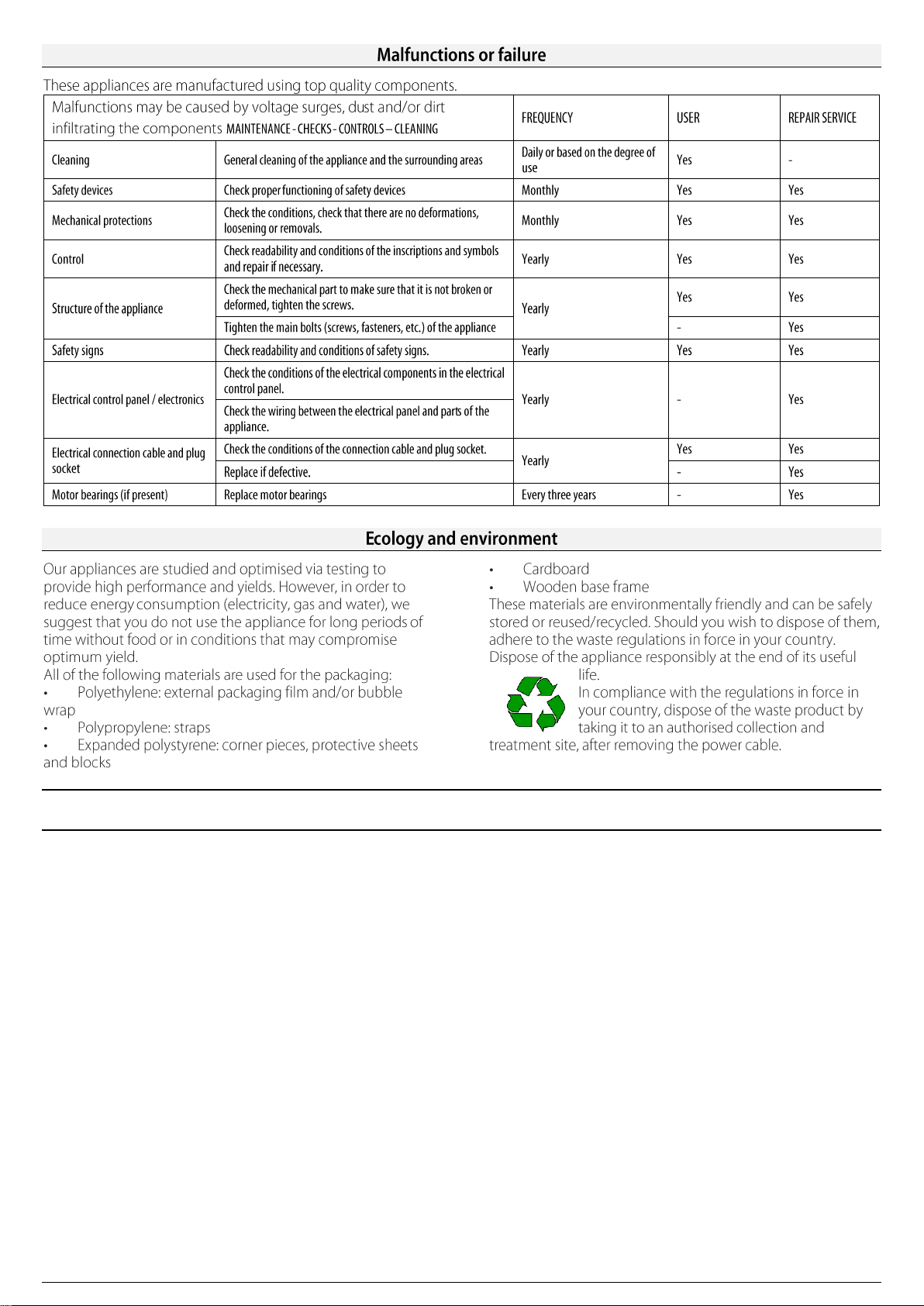
Malfunctions
Malfunctions do not always depend on the quality of the components
used. These appliances are manufactured using top quality
components. Failures may be caused by voltage surges, or dust and
dirt in the operating components.
In any case, if you suspect the presence of anomalies close the gas
shut-off cock and inform the authorised after-sales service.
Unauthorised persons should never attempt to repair the appliance, or carry out maintenance. Tampering with the appliance
voids the warranty!
Operational checks
Before the unit is delivered to the user the following checks must be
carried out.
THERMAL CAPACITY
Check that the type and group of gas where the unit is to be used is
the same as that indicated on the plate. If it is not, the unit must
either be converted or adapted. In this case please refer to the
paragraph: “Conversion or Adaptation”.
Check that the right nozzles have been installed.
Refer to the nozzle table and check that the nozzles indicated in the
table are the same as those installed on the unit.
An additional check of thermal capacity entails verifying the gas
consumed with the volumetric method: start the burner and after
approximately 10 minutes (in working conditions) check that the gas
flow (in m3/h or in kg/h) corresponds to that in the nozzle table.
APPEARANCE OF THE FLAME AND PRIMARY AIRFLOW
Use the inspection hole "I" (fig.2) to check the flame.
The flame should be blue and there should be no yellow dots in it; it
must be stable at its base.
If the colour of the flame tends towards yellow, it means the primary
airflow is not adjusted properly. If the primary airflow is too fast the
flame will be short and tend to burn above the burner.
The appearance of the flame must also be checked 15 minutes after
the appliance has been running at full power. The flame must remain
stable even when passing quickly from minimum to maximum.
USER'S INSTRUCTIONS
The user must be trained on the correct use and functions of the
appliance. We would like to point out that any alterations made to the
room where the unit is installed could influence the amount of air
used for combustion and for this reason the appliance must be
checked again. When these checks have been done, test the unit for
leaks.
Replacing parts
Only qualified personnel should replace faulty parts. Prior to
commencing any kind of work, disconnect the unit from the gas
distribution network.
After having removed the control panel, all the functional parts of the
appliance are easily accessible
Only order spare parts from the manufacturer or an authorised reseller.

GB / IE - 6
5410.260.00
Part 4
Maintenance and cleaning
Cleaning and care of the appliance
CLEANING:
WARNING! The unit must be cold to clean it.
Keeping the appliance clean is very important for a long and trouble-
free working life.
The removable parts should be washed separately with warm water
and detergent, then rinsed in running water.
Do not use harsh or abrasive detergents to clean the stainless steel
parts. Iron cleaning pads should not be used as they cause the
formation of rust. For the same reason, avoid contact with ferrous
materials.
When cleaning, avoid using abrasive paper or cloth; instead and only
in special cases you can use pumice stone powder; we recommend
using sponges (ex. Scotch) to remove stubborn deposits. You can
also use common sprays for cleaning ovens and grills to remove
stubborn deposits. If spray products are used, follow the
manufacturer’s instructions.
To minimise the emission of polluting substances in the environment
we suggest cleaning the appliance with products that are at least
90% biodegradable.
Safety precautions
REMEMBER THAT THE APPLIANCE:
▪Must never be left unattended when it is being used!
▪When the unit is switched on, its sides get very hot so please
take great care!
▪The appliance is intended for professional use and therefore
only qualified personnel should use it!
▪Installation as well as any conversion or adaptation to a different
type of gas must be carried out in accordance with current laws
and only by qualified and authorized personnel.
▪At least once a year have the appliance checked by qualified
personnel.
▪All the parts that come into contact with oil or fat during use,
should be cleaned regularly as indicated in the chapter
“Cleaning and Care”.
FIRE:
If the oil catches fire, close the gas shut-off cock immediately, cover
the tub with the cover and use a suitable extinguisher.
EN - 7
.
The Manufacturer declines any responsibility for damage caused by improper or incorrect installation or maintenance of the appliance, or
failure to observe safety regulations!
DE / AT / CH - 1
5410.260.00
GAS-STANDFRITTEUSEN
Das in diesem Handbuch beschriebene Gerät wurde unter
Beachtung der Anforderungen der Normen UNI EN 203 und UNI EN
437 gebaut.
Dieses Gerät ist ausschließlich für das Kochen und Garen von
Speisen vorgesehen. Jeder andere Gebrauch gilt als ungeeignet. Es
ist für den Einsatz in Großküchen bestimmt und darf nur von
qualifiziertem Personal betrieben werden.
Gerät nur unter Aufsicht betreiben! Außerdem ist es
empfehlenswert, einmal jährlich eine Kontrolle von qualifiziertem
Personal durchführen zu lassen.
Im Schadensfall oder bei mangelhaftem Betrieb das Gerät
ausschalten.
Es ist empfehlenswert, das Gerät unter einer Abzughaube aufzustellen, um die während des Garens erzeugten Dämpfe
abzuleiten.
Es ist besonders darauf zu achten, dass sich die Geräteoberflächen während des Betriebs stark erhitzen (Verbrennungsgefahr).
Der Anschluss, die Installation und die Wartung müssen von Fachpersonal gemäß den Vorschriften und Gesetzen des Landes
sowie in Übereinstimmung mit dieser Gebrauchsanweisung durchgeführt werden.
Die vorliegende Installationsanweisung gilt für gasbetriebene
Friteusen der Kategorie II2H3+.
Das Typenschild aus selbsthaftendem Polyester befindet sich
hinter der Bedienblende (im Geräteinneren).
Es enthält folgende Daten; Beispiel:
Modell:
FRS35G7
FRS70G7
Seriennummer:
xxxxxx
Kategorie:
II2H3+
Baujahr:
xxxx
Nennwärmebelastung:
11.5 kW
23 kW
Bauart:
A1
A1;B21
Prüfgrundlage:
UNI EN 203-1
Anschlussdruck:
G30
G20
28-30/37 mbar
20 mbar
Anschlusswert.:
G30
G20
0.91
1.22
Kg/h
m3/h
1.82
2.44
Kg/h
m3/h
Das Zusatzschild, ebenfalls aus selbstklebender Polyesterfolie, ist
neben dem Typenschild angebracht und enthält alle Informationen
über die Einstellung des Gerätes. Das Gerätemodell FRS35G ist mit
zwei Brennern und einer Gasanschlussrampe ausgestattet. Das
Gerätemodell FR 70G ist mit vier Brennern und zwei
Gasanschlussrampen ausgestattet. Der Anschluss für die
Verbindung mit der Gasleitung "G"(Abb. 1) entspricht den
Vorschriften ISO 7/1 und ISO 228/1 (DK) mit ø ½” und befindet sich
an der Geräteunterseite.
Die Gerätestruktur ist aus Edelstahl, die Brenner aus Stahl gebaut.
Alle Modelle sind mit höhenverstellbaren Stellfüßen ausgestattet.
Die Gas-Hauptleitung besteht aus verzinktem Stahl, die
Anschlussleitungen vom Hahn zum Brenner aus Kupfer.
ACHTUNG!
Zwischen dem Gerät und der Gasversorgungsleitung einen
Absperrhahn einbauen.
Vor der Geräteinstallation unbedingt beim
Gasversorgungsunternehmen eine
Installationsgenehmigung einholen und die Daten
der Geräteeinstellung (Typenschild) mit der örtlichen
Gasversorgung konfrontieren.
Die Geräteverpackung entfernen, die Schutzfolie abnehmen und
eventuelle Klebstoffrückstände mit einem geeigneten Lösungsmittel
entfernen. Das Verpackungsmaterial muss vorschriftsmäßig entsorgt
werden (nähere Details dazu im Kapitel „UMWELTSCHUTZ“).
Bevor das Gerät angeschlossen wird, ist auf dem Geräteschild
festzustellen, ob das Gerät für die vorhandene Gasart eingerichtet
und zugelassen ist.
Falls die auf dem Geräteschild angegebene Gasart mit der
vorhandenen Gasart nicht übereinstimmt, verweisen wir auf
Abschnitt ”UMSTELLUNG UND ANPASSUNG”.
Der Anschluss an das Gaszuleitungsnetz muss mit Metallrohren mit
entsprechendem Durchmesser und unter Zwischenschaltung eines
anerkannten Absperrhahns durchgeführt werden.
Sollten Schlauchleitungen zur Anwendung kommen, müssen diese
gemäß müssen diese gemäß DIN 3383 Teil 1 oder DIN 3384 (für
Deutschland) und den gültigen Normen aus rostfreiem Stahl (für die
Schweiz und für Österreich) bestehen. Während der Installation sind
alle geltenden Vorschriften zu berücksichtigen:
▪Sicherheitsnorm UNI-CIG 8723, Gesetz Nr. 46 vom 5. März 1990
und Rundschreiben Nr. 68.
▪Regionale bzw. lokale Bauvorschriften
▪Geltende Unfallverhütungsgesetze
▪Brandschutzvorschriften
▪Entsprechende IEC-Vorschriften

DE / AT / CH - 2
5410.260.00
Für Deutschland
▪DVGW-Arbeitsblatt G600 (TRGI) „Technische Regeln für
Gasinstallation“.
▪TRF „Technische Regeln für Flüssiggas“.
▪Richtlinien und Bestimmungen des
Gasversorgungsunternehmens (EUV).
▪DVGW-Arbeitsblatt G634 „Installation von Großküchen-
Gasverbrauchseinrichtungen“.
▪Einschlägige Rechtsverordnungen.
Für Schweiz
▪Vorschriften der Kantonalen Feuerversicherungs-Anstalten
(VKFA).
▪Richtlinien der SUVA.
Das Gerät zur Ableitung der beim Kochen entstehenden Dämpfe
vorzugsweise in einem gut gelüfteten Raum oder unter einer
Dunstabzugshaube aufstellen.
Das Gerät ist an der Rückseite mit einem Potentialausgleich “N”
(Abb. 1) ausgestattet.
Das Gerät kann sowohl freistehend als auch gemeinsam mit anderen
Geräten installiert werden.
Zwischen dem Gerät und eventuellen Wänden aus brennbarem Material,
Trennwänden, Küchenmöbeln oder nebenstehenden Geräten
mindestens 80 mm Abstand halten.
Die Kontaktflächen müssen mit nicht brennbarem
Wärmeisoliermaterial verkleidet werden.
ACHTUNG!
Das Modell FSR35G7 muss mit dem dazu vorgesehenen Bügel „F“
(Abb. 2) am Fußboden befestigt werden.
Nach der Installation die Anschlüsse auf ihre Dichtheit prüfen. Zur
Suche nach Leckstellen einen nicht korrosiven Schaum, wie z.B.
Lecksuchsprays verwenden.
Bei der Dichtheitsprüfung auf keinen Fall offene Flammen benutzen! Der Hersteller übernimmt keine Garantieverpflichtung für
Beschädigungen, die aufgrund einer Nichtbeachtung der Installations- und Bedienungsanleitung oder durch fahrlässige
Bedienung entstehen. Außerdem übernimmt er keine Garantieverpflichtungen für einen nicht mit den gültigen Normen und
Brandschutzvorschriften konformen Anschluss.
Für die Geräte FSR35G7 (Typ A1) und FSR70G7 (Typ A1,B21) ist ein Anschluss an den Kamin nicht nötig.
Der Leitungsdruck muss folgenden Daten entsprechen.
FLÜSSIGGAS
ZULÄSSIG
zwischen 20/25 und 35/45 mbar
NICHT ZULÄSSIG
unter 20/25 bzw. über 35/40 mbar
ERDGAS
H
ZULÄSSIG
zwischen 17 und 25 mbar
NICHT ZULÄSSIG
unter 17 bzw. über 25 mbar
Sollte der Leitungsdruck am Aufstellungsort nicht den oben
genannten Werte entsprechen, das GVU benachrichtigen und keine
Inbetriebnahme vornehmen, bevor die Ursache nicht geklärt und
behoben ist.
Der Anschlussdruck ist mit einem U-Rohr Manometer (Auflösung
mind. 0.1mbar) messbar. Das Manometer kann am Druckanschluss
hinter der Blende, “H” (Abb. 6) angeschlossen werden.
1. Die Bedienblende abnehmen.
2. Die Schraube und Dichtungsscheibe vom Druckanschluss
nehmen und das Manometer anschließen.
3. Das Gerät gemäß der Bedienungsanleitung in Betrieb nehmen
und prüfen, ob der angegebene Druck im zulässigen Bereich
liegt.
4. Das Manometer wieder abnehmen und die Schraube mit dem
Dichtring wieder am Druckanschluss anordnen.
5. Die Bedienblende und Drehschalter wieder montieren.
This manual suits for next models
1
Table of contents
Languages:
Other Tecnoinox Fryer manuals


