Tecnosystemi PICO HP2 55 User manual

22
CODE
: 11104038A -11104038C -11104038E-11104038L-11104038N-11104038P
WALL-MOUNTED STATIC INTAKE-EXTRACTOR UNIT WITH HEAT RECOVERY
“PICO
HP2 30 - HP2 55 - HP2 80”
CODE: 11104038H - 11104038R
WALL-MOUNTED CROSS FLOW STATIC INTAKE-EXTRACTOR UNIT WITH
HEAT RECOVERY “PICO RECO 100”
USER MANUAL
Vers.05-28/01/2017
via dell’Industria 2/4 - Z.I. San Giacomo di Veglia 31029 Vittorio Veneto (Treviso), Italy
Tel/Phone +39 0438.500044 Fax +39 0438.501516
WWW.TECNOSYSTEMI.COM

23
INTRODUCTION
This manual includes the technical description, operation, installation and assembly instructions,
technical data for the intake extractor unit with energy regeneration “PICO HP2”, “PICO RECO
100”, hereinafter referred to as recovery unit.
The recovery unit was designed to ensure the air exchange in apartments, holiday farms, hotels,
bars and, in general, domestic and public places.
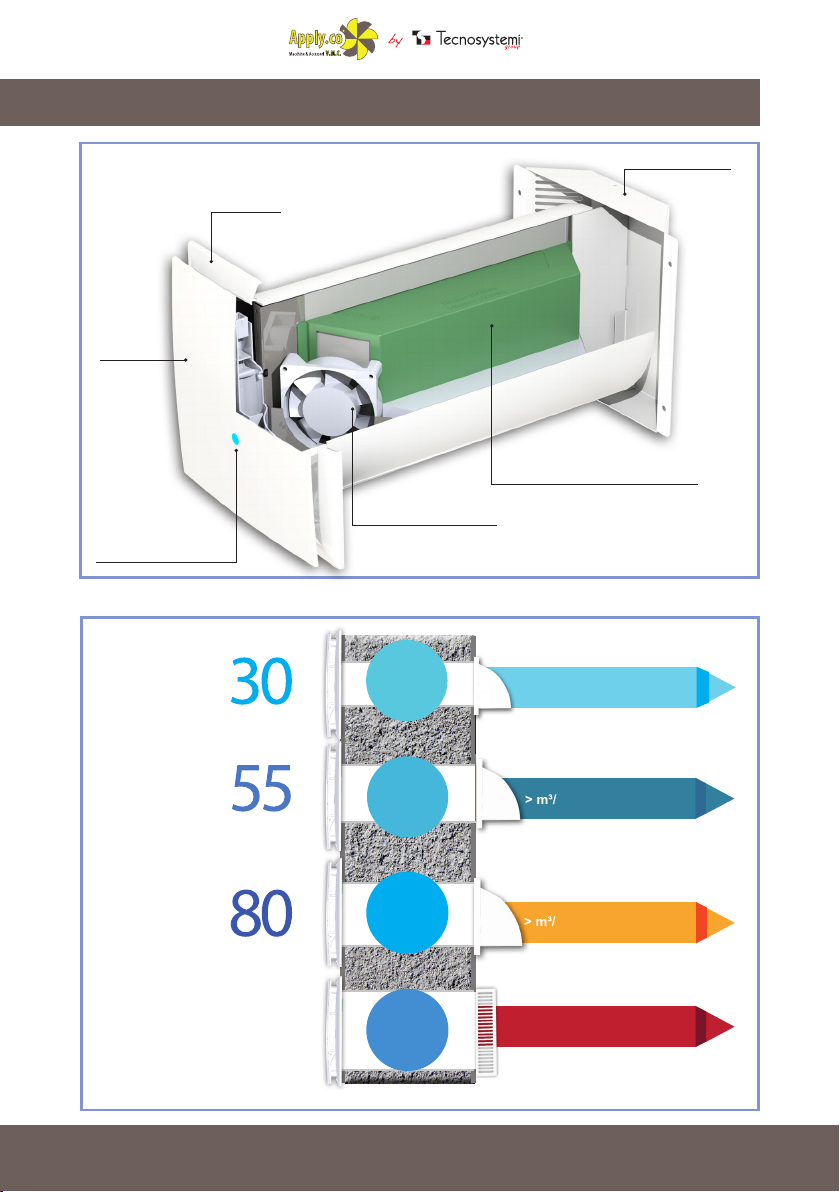
The recovery unit is tted with a ceramic exchanger which allows the air recirculation thanks to the
energy regeneration with the heat from the intake air.
The recovery unit was designed to be installed in premises on walls with a thickness between 310 mm
and 500 mm (optional tube L=1,500 mm), for the “Pico Reco 100”, the minimum thickness is 370 mm.
The recovery unit was tested for continuous operation connected always to be mains supply.
The transported air must not contain ammable or explosive mixtures, chemical substance
vapours, large dust particles, soot and oil particles, dangerous substances, brous
materials, pathogenic agents or other harmful substances.
The recovery unit was designed for application within premises with a room temperature varying
from -20°C to +50°C and relative humidity of up to 80%.
THE RECOVERY UNIT WAS NOT DESIGNED FOR USE BY CHILDREN, PERSONS
WITH PHYSICAL OR MENTAL DISABILITIES, PERSONS WITH SENSORY
DISABILITIES, OR PERSONS WITHOUT ADEQUATE QUALIFICATIONS.
THE INSTALLATION AND CONNECTION OPERATIONS CAN BE PERFORMED
ONLY BY QUALIFIED PERSONNEL AFTER FOLLOWING THE ADEQUATE
SAFETY TRAINING.
UNATTENDED CHILDREN SHOULD NOT BE ALLOWED ACCESS TO THE SITES
WHERE THE FAN IS INSTALLED.
MAIN TECHNICAL PARAMETERS
Read the user manual carefully before use and installation of heat reversible recovery unit with
individual chamber with energy regeneration.
The installation and the operation of the recovery unit must be carried out in compliance with the
user manual, as well as with applicable legislations, local and national laws and technical and
electrical regulations. The warnings, contained in the user manual, should be heeded, as they
contain vital information for personal safety.
Failure to follow the safety rules can result in damage to the recovery unit. Read this manual
carefully and keep it for as long as the recovery unit is used.
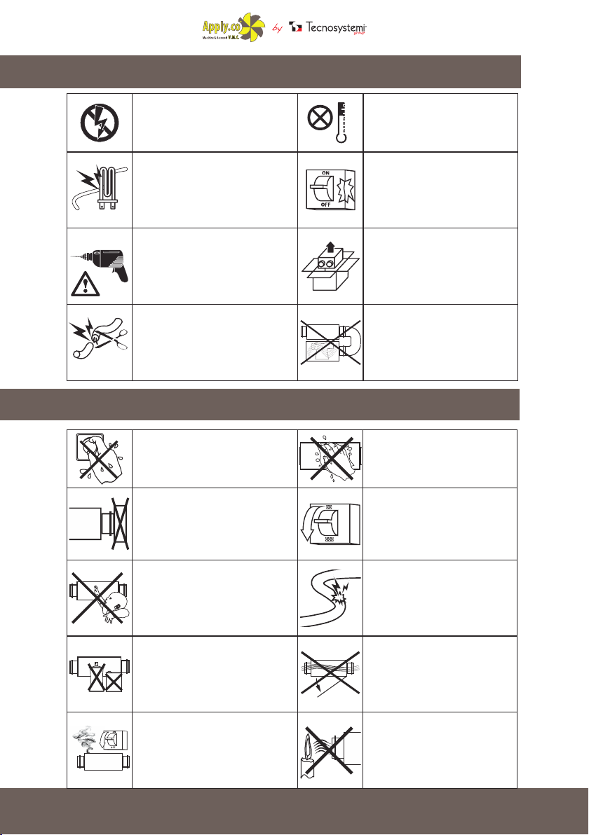
Legend of symbols used in the manual:
SAFETY REQUIREMENTS
USE OF THE RECOVERY UNIT
WARNING
PROHIBITION

24
Do not touch the controls and the
remote controls with wet hands. Do
not perform maintenance operations
on the recovery unit with wet hands.
Do not wash the recovery unit
with water. Protect the parts of
the recovery unit from water
seepage.
Disconnect the recovery
unit from the mains before
maintenance.
Do not damage the power cord
when using the recovery unit.
Do not place objects on the
power cord.
Do not open the recovery unit
during operation.
Make sure that the air emitted by
the recovery unit is not directed
at naked ames or candles.
Do not block the air duct, when the
recovery unit is on.
Do not let children use the recovery
unit.
Keep explosive and ammable
products away from the recovery
unit.
In the event of unusual noises or
smoke, disconnect the recovery
unit from the wall outlet and contact
customer service.
ASSEMBLY WARNINGS
The recovery unit must be
disconnected from the mains
supply before carrying out any
installation or repair operation.
The recovery unit must not be used
outside the temperature range,
indicated in the user manual,
or in aggressive or explosive
atmospheres.
Do not place any radiators or other
devices near the power cord of the
recovery unit.
Do not use damaged equipment
or wires to connect the recovery
unit to the mains.
Carefully remove the recovery
unit from the packaging.
Use the recovery unit only
in accordance with the
manufacturer's specications.
When installing the recovery
unit, follow the specic safety
regulations for electrical
equipment.
Do not change the length of the
power cord at your own discretion.
Do not bend the power cord. Do
not damage the power cord.
SAFETY OPERATING WARNINGS

25
EXTERNAL DIMENSIONS OF RECOVERY UNITS MOD. “HP2”
TECHNICAL DATA OF RECOVERY UNITS MOD. “HP2”
DIMENSIONS (mm)
E
EXTERNAL TUBE Ø
MODEL PICO HP2 - 30 PICO HP2 - 55 PICO HP2 - 80
SPEED 123123123
POWER SUPPLY VOLTAGE 12 Vdc 12 Vdc 12 Vdc
POWER (W) 0.46 0.51 0.57 0.85 0.9 1.1 2 2.1 2.4
MAXIMUM CURRENT CONSUMED (mA) 38 42 47 65.5 73 81 162 180 200
MAXIMUM AIR FLOW RATE (m³/h) 26 28.5 32 40 45 50 65 72 80
RPM (min-1) 1863 2070 2300 2106 2340 2600 2350 2610 2900
SOUND PRESSURE AT 1m (dB(A)) 17 19 21 21 23 25 24 26 28
SOUND PRESSURE AT 3 m (dB(A)) 15 17 19 19 21 23 22 24 26
MAXIMUM AIR TEMPERATURE (°C) FROM -10 A +50 FROM -10 A +50 FROM -10 A +50
REGENERATOR EFFICIENCY ≤90% ≤90% ≤90%
HEAT EXCHANGE FILL MEDIA CERAMIC CERAMIC CERAMIC
TUBE DIMENSIONS (mm) Ø 103 Ø 128 Ø 153
PROTECTION IP 24 IP 24 IP 24
CODE A B C Ø E
11104038L 154 500 86 103 35
11104038N 186 500 101 128 35
11104038P 186 500 101 153 35
11104038A 154 500 86 103 35
11104038C 186 500 101 128 35
11104038E 186 500 101 153 35

26
DIMENSIONS (MM)
SPEED MIN 1 AVG. 2 MAX. 3
POWER SUPPLY VOLTAGE 12Vdc
POWER (W) 6,6 7,7 8,4
MAX. CURRENT CONSUMED (mA) 550 640 700
MAX. AIR FLOW RATE (m3/h) 70,3 81,7 91,3
RPM (min-1) 3395 4070 4500
SOUND PRESSURE AT 1m (dB(A)) 47,5 51,5 53,5
SOUND PRESSURE AT 3m (dB(A)) 43,5 47,5 49,5
MAX. AIR TEMPERATURE (°C) FROM -10°C TO +50°C
REGENERATOR EFFICIENCY ≤95%
HEAT EXCHANGE FILL MEDIA POLYESTER
EXTERNAL TUBE DIAMETER (mm) Ø 204
PROTECTION IP 24
EXTERNAL DIMENSIONS OF RECOVERY UNIT MODEL
“RECO 100”
TECHNICAL DATA OF RECOVERY UNIT MOD. “RECO 100”
DIMENSIONS (mm)
51
EXTERNAL TUBE Ø

27
SPEED MIN 1 AVG. 2 MAX. 3
POWER SUPPLY VOLTAGE 12Vdc
POWER (W) 6,6 7,7 8,4
MAX. CURRENT CONSUMED (mA) 550 640 700
MAX. AIR FLOW RATE (m3/h) 70,3 81,7 91,3
RPM (min-1) 3395 4070 4500
SOUND PRESSURE AT 1m (dB(A)) 47,5 51,5 53,5
SOUND PRESSURE AT 3m (dB(A)) 43,5 47,5 49,5
MAX. AIR TEMPERATURE (°C) FROM -10°C TO +50°C
REGENERATOR EFFICIENCY ≤95%
HEAT EXCHANGE FILL MEDIA POLYESTER
EXTERNAL TUBE DIAMETER (mm) Ø 204
PROTECTION IP 24
OPERATION OF RECOVERY UNITS
MODEL “PICO HP2” AND MODEL “PICO RECO 100”
The recovery unit consists of a xed length circular air duct, ventilation unit and external grille.
The two motors, two lters and the exchanger are inside the duct.
The lters are protected in order to purify the supply air and to prevent foreign objects
entering the exchanger and the fans.
The recovery unit generates a visual alarm (red LED indicator) as a reminder to clean or replace
the lter every 1,500 operating hours.
The ceramic exchanger (for the “PICO HP2” models) uses the thermal energy of the intake air in
order to heat the intake air ow.
For the “PICO RECO 100” model, the ll media is made of polyester.
The exchanger is tted with a draw cord on the inside to make it easier to extract (for the “PICO
HP2” models) and special clip for the “PICO RECO 100” model.
The ventilation unit must be installed on the inside part of the wall.
The external grille must be installed on the external part of the wall in order to prevent
water and other objects from entering the recovery unit.
CONSTRUCTION DETAIL OF MODEL “PICO HP2”
FILTER 1
EXRASLIM GRILLE
FILTER 2
EXTERNAL GRILLE
FILL MEDIA
DETAIL OF CERAMIC
EXCHANGE FILL MEDIA
3-SPEED MOTOR
LED INDICATOR
FUNCTION
SETTING
DECORATIVE
FRONT PANEL

28
CONSTRUCTION DETAIL OF MODEL “RECO 100”
DECORATIVE
FRONT PANEL
LED INDICATOR
FUNCTION SETTING
3-SPEED
MOTOR
HIGH-EFFICIENCY CROSS FLOW
FILL MEDIA
EXRASLIM GRILLE
EXTERNAL GRILLE
> m³/h 80
Ø HOLE 153 mm
> m³/h 50
Ø HOLE 128 mm
MAX.
POWER
0.57 W
MAX.
POWER
2.4 W
MAX.
POWER
1.1W
MAX.
POWER
8,4 W
100
reco
PICO> m³/h 93
Ø HOLE 204 mm
> m³/h 32
Ø HOLE 103 mm
HP2
PICO
HP2
PICO
HP2
PICO

29
OPERATING MODES OF THE RECOVERY UNITS
THE DEVICE WORKS FOR 70 SECONDS IN
EXTRACTION MODE AND 70 SECONDS IN
AERATION MODE, WITH THE OPTION TO
REGULATE THE THREE SPEEDS. IN THE CASE
OF THE RECOVERY UNIT MOD. “PICO RECO
100”, THE FANS OPERATE SIMULTANEOUSLY
(EXTRACTION AND AERATION)
THE DEVICE WORKS IN INTERNAL AIR EXTRACTION
MODE ONLY, WITH THE OPTION TO REGULATE THE
THREE SPEEDS
THE DEVICE WORKS IN AERATION MODE ONLY,
TAKING IN AIR FROM OUTSIDE AND INTRODUCING IT
INTO THE ROOM. OPTION TO REGULATE THE THREE
SPEEDS PROVIDED
THE DEVICE IS IN STANDBY.
WHEN THE AIR IN THE ROOM EXCEEDS THE
HUMIDITY LEVEL, THAT CAN BE SET AT 40%,
50% OR 60%, THE DEVICE SWITCHES INTO
RECOVERY MODE UNTIL THE HUMIDITY LEVEL
L FALLS WITHIN THE SET VALUE
THE DEVICE IS IN STANDBY. WHEN THE AIR IN THE
ROOM EXCEEDS THE HUMIDITY LEVEL, THAT CAN BE
SET AT 40%, 50% OR 60%, THE DEVICE SWITCHES INTO
EXTRACTION ONLY MODE UNTIL THE HUMIDITY LEVEL
FALLS WITHIN THE SET VALUE
THE RED FLASHING LED INDICATES THE NEEDTO PERFORM THE MAINTENANCE OF FILTERS AND THE
FILL MEDIA
WHEN THE BLUE LED COMES ON, IT INDICATES ACCESS TO THE HUMIDITY VALUE
SETTINGS MODE. IT IS POSSIBLE TO SET THE HUMIDITY THRESHOLD TO THREE
DIFFERENT VALUES 40%, 50% O 60%
EXTRACTION
AERATION
AUTO1
AUTO2
FILTER MAINTENANCE
SETTING THE HUMIDITY VALUE
AUTO2
RECOVERY UNIT
70 sec.
AUTO1
70 sec.

30
The fan is controlled by a remote control. The remote control has greater control functions.
For models “PICO HP2” AND “PICO RECO 100”
USE OF REMOTE CONTROL
ON
MODE
OFF
AUTO1
AUTO2
Recovery unit
(blue LED)
the device works for 70
seconds in extraction mode
and 70 seconds in aeration
mode, with the option to
regulate the three speeds.
In case of the recovery unit
model “Pico Reco 100”, the
fans operate simultaneously
(extraction and aeration).
Extraction
(green LED)
the device works in internal air
extraction mode only with the
option to regulate the three
speeds
RESET FILTER
MAINTENANCE
PRESS AND HOLD
FOR 3 SECONDS
Button
Fan OFF
Button
Fan ON
Button
Change mode
Change speed
Aeration
(purple LED)
the device works in aeration mode
only, aspirating external air and
introducing it into the room. Option to
regulate the three speeds provided.
Auto 2
(white LED)
the device is in standby, when
the air in the room exceeds the
threshold of settable humidity
at 40%, 50% or 60%, the device
switches to extraction only
mode until the humidity level
falls within the set values.
Auto 1
(yellow LED)
the device is in standby. When
the air in the room exceeds the
threshold of settable humidity
at 40%, 50% or 60%, the device
switches to recovery only mode
until the humidity level falls
within the set values.
Button
Maximum speed
(Humidity value 60%)
Button
Medium speed
(Humidity value 50%)
Button
Low speed
(Humidity value 40%)
Setting the
humidity value

31
ON
MODE
OFF
AUTO1
AUTO2
SETTING THE HUMIDITY VALUE
To set the value of the desired humidity (40%, 50% or 60%) proceed as follows:
• Using the remote control, select AUTO 1 mode 1 (yellow LED) or AUTO 2
(white LED).
• Press the "ON" key.
• The colour of the LED changes from yellow (or white) to blue.
• Use the keys for changing the speed of the fans to select the
desired humidity value. Key for minimum speed 40% humidity, key for
medium speed 50% humidity, key for maximum speed 60% humidity
• By selecting the desired humidity value, the colour of the LED will change from blue to
yellow (or white) and you will notice the following:
• Selected value 60% (key for maximum speed), the LED changes from blue to yellow
(or white) and you will see 3 ashes and hear an audible signal. When this operation is
completed, the yellow (or white) LED will remain xed to conrm that the humidity value
you selected has been set correctly.
• Selected value 50% (key for medium speed), the LED changes from blue to yellow
(or white) and you will see 2 ashes and hear an audible signal. When this operation is
completed, the yellow (or white) LED will remain xed to conrm that the humidity value
you selected has been set correctly.
• Selected value 40% (key for minimum speed), the LED changes from blue to yellow
(or white) and you will see 1 ash and hear an audible signal. When this operation is
completed, the yellow (or white) LED will remain xed to conrm that the humidity value
you selected has been set correctly.
N.B: The factory setting for the humidity value is 40%
Setting the humidity value

32
REMOTE CONTROL FUNCTIONS
ON
OFF
DESCRIPTION OF USE OF REMOTE CONTROL KEYS
1. Turn on
- On / turning the appliance on
- Setting the humidity value
2. Turn off
- Off / turning the appliance off
- Reset alarm lter cleaning
3. Speed setting
Minimum speed / humidity value 40%
Medium speed / humidity value 50%
Maximum speed / humidity value 60%
4. Operating Symbols
MODE
It allows the following operation modes to be selected
Recovery unit (blue icon)
The device, for the recovery units model “PICO HP2”, works for 70 seconds in extraction
mode and 70 seconds in aeration mode, with the possibility to regulate the three speeds. For
the model “PICO RECO 100”, the extraction and the aeration of the air occur simultaneously.
Extraction (green icon)
The device works in internal air extraction mode only, with the possibility to regulate the three
speeds
Aeration (purple icon)
The device works in aeration mode only, taking in air from outside and introducing it
into the room. Option to regulate the three speeds provided.
Auto1 (yellow icon)
The device is in stand-by. When the air in the environment exceeds the threshold of
settable humidity at 40%, 50% or 60%, the device starts in the recovery mode until it
brings the humidity back within the set value.
Auto2 (white icon)
The device is in stand-by. When the air in the environment exceeds the threshold of
settable humidity at 40%, 50% or 60%, the device starts in the extraction only mode
until it brings the humidity back within the set value.
Filter maintenance (red LED)
Flashing red led
It indicates the need to perform the maintenance of lters and the ll media
Setting the humidity value (blue LED)
When the blue LED comes on, it indicates access to the humidity value settings mode. It is
possible to set the humidity threshold on three different values 40%, 50% or 60%.
MODE
AUTO2
AUTO1

33
1) Install the duct in the wall, with a 1° inclination towards the outside. The air duct must
Be ush with the internal wall and should protrude from the external wall for 5 mm (only pico
reco 100 model).
MOUNTING RECOVERY UNITS “PICO HP2 / RECO 100”
WARNINGS FOR THE ASSEMBLY
To mount the recovery unit, make a circular hole through the wall that is big enough to allow
insertion of the tube supplied for the various recovery unit models.
NOTE:
for diameters of the external tube, please refer to page 4 for the recovery units mod. “PICO HP2”
and page 5 for the recovery unit mod. “PICO RECO 100”
WARNING!
THE RECOVERY UNIT SHOULD NOT BE INSTALLED IN
PLACES WHERE THE AIR DUCT MIGHT BE BLOCKED BY
BLINDS AND SHUTTERS, ETC. IN ORDER TO PREVENT
THE ACCUMULATION OR DEPOSIT OF DUST. MOREOVER,
THE BLINDS MIGHT OBSTRUCT THE NORMAL AIR FLOW IN
THE ROOM, MAKING THE OPERATION OF THE RECOVERY
UNIT INEFFICIENT.
WARNING!
DO NOT PLACE THE DEVICE ABOVE DELICATE FURNITURE
OR PICTURES. DO NOT PLACE THE DEVICE ABOVE OR
NEAR ROOM THERMOSTATS.
5 mm
1°
INSIDE OUTSIDE
Ø 103-128-153 - 204
Prepare a circular hole positioned as shown in the
adjacent gure

34
LEGEND:
A: Circular wall duct
B: Wall mount fastening ring
C: Through holes for
power supply
Air duct
2) Prepare the power cable (see pic.1) taking care to route it, either from
the right or left, in the upper part of the duct in correspondence with the duct hole.
The mains can be laid out by means of a buried electrical sheath or an adequate electrical
channel which will contain the power cord.
The cord complete with plug must protrude from the wall for approximately 10 cm.
4) Align the ring to the wall with the air duct (see pic. 2)
3) Insert the circular duct in the hole made in the wall. Fill the spaces between the wall and the
duct with silicone, foam or other suitable material. The air duct must be placed wired to the
internal wall.
5) Fix the ring making four holes in the wall and using the four 4x30 screws and the four
dowels included in the supply. (see pic. 3)
A
B
Cpic.1
Wall ring
pic.2
pic.3

35
6) Insert the elements consisting of the ceramic exchanger and the lters (in the case of mod.
“PICO HP2”) and the ll media in polyester and the fans in the case of the recovery unit “PICO
RECO 100”.
“PICO HP2”
pic.1 pic.2
“PICO RECO 100”
ASSEMBLY OF THE RECOVERY UNIT INTAKE GRILLE
1 Remove the external grille in order to gain access to the xing holes..
Remove the upper part of the external ventilation grille. (see pic. 1)
MODEL
DIMENSIONS (mm)
B H L L1 L2 DIAMETER (D)
“PICO HP2” 154 110 15 45 87 100 1.2
“PICO HP2” 186 142 15 45 101 125 1.2
“PICO HP2” 186 142 15 50 101 150 1.2
7) Attach the fan unit to the wall ring

36
4Fix the back part of the grille to the
wall with 4x30 screws included. (see pic. 3)
pic.2
pic.4
pic.3
pic.1
Grey front part
Grey back part
External grille mounted
3 Mark the xing holes for the external ventilation grille and drill.
For the sake of convenience, use the back part of the grille.(see pic.2)
2Insert the wall plugs provided in the holes.
5 Assemble the upper part of the grille. (see pic. 4)

37
Grey front part
5 Assemble the upper part of the grille. (see pic. 4)
1 Mark the xing holes for the external ventilation grille and drill, inserting
the wall plugs provided.
ASSEMBLY OF THE INTAKE GRILLE
RECOVERY UNITS MODEL “PICO RECO 100”
322,5
300,9
160
6(5x)
4
50
SU 90° R 1
SU 90° R 1
GIU' 45° R 1
SU 45° R 1
SU 45° R 1
GIU' 45° R 1
260
51
1
45°
6
221,66
14
42
4
120,7
224
C20002320-rev1
Approvato
Verificato
Disegnato
Modifica
Data
Numero
Assieme:
Approvato:
Verficato:
DISEGNATO:
Tolleranze:
Materiale:
Codice:
Data:
Scala:
Cod.Materiale:
Descrizione:
Trattamenti:
TECNOSYSTEMI srl
Produzione accessori
per il
condizionamento
Floriano
Tel.:0438/500044 Fax.:0438/501516
Via Mattei 31029 Vittorio Veneto (TV)
TECNOSYSTEMI s.p.a
+
FORI
TOLLERANZA
CLASSE
A 6
DA 3
FINO A 3
0,1
+0,1
A 120
DA 30
A 30
DA 6
-+
-0,2 -
+0,3
-
SCOSTAMENTI IN mm
A 4000
DA 2000
A 6
DA 3
"MEDIA"
TOLLERANZA
CLASSE
FINO A 3
0,1
+
-0,1
A 120
DA 30
A 30
DA 6
+
-+
-0,2 -0,3 -
+
-
+
-
+
-
+2
1,2
0,8
0,5
A 400
DA 120
A 1000
DA 400
A 2000
DA 1000
+
1:2
Protezione esterna
08/10/2015
1.0037 (S235JR)
TAV.N.:
1 di 1
La TECNOSYSTEMI si riserva, a termini di legge, la proprietà del presente del presente
disegno con divieto di riprodurlo o comunicarlo a terzi senza la sua autorizzazione
allungato in altezza
14/12/15
01
Floriano
322,5
300,9
160
6(5x)
4
50
SU 90° R 1
SU 90° R 1
GIU' 45° R 1
SU 45° R 1
SU 45° R 1
GIU' 45° R 1
260
51
1
45°
6
221,66
14
42
4
120,7 224
C20002320-rev1
Approvato
Verificato
Disegnato
Modifica
Data
Numero
Assieme:
Approvato:
Verficato:
DISEGNATO:
Tolleranze:
Materiale:
Codice:
Data:
Scala:
Cod.Materiale:
Descrizione:
Trattamenti:
TECNOSYSTEMI srl
Produzione accessori
per il
condizionamento
Floriano
Tel.:0438/500044 Fax.:0438/501516
Via Mattei 31029 Vittorio Veneto (TV)
TECNOSYSTEMI s.p.a
+
FORI
TOLLERANZA
CLASSE
A 6
DA 3
FINO A 3
0,1
+0,1
A 120
DA 30
A 30
DA 6
-+
-0,2 -
+0,3
-
SCOSTAMENTI IN mm
A 4000
DA 2000
A 6
DA 3
"MEDIA"
TOLLERANZA
CLASSE
FINO A 3
0,1
+
-0,1
A 120
DA 30
A 30
DA 6
+
-+
-0,2 -0,3 -
+
-
+
-
+
-
+2
1,2
0,8
0,5
A 400
DA 120
A 1000
DA 400
A 2000
DA 1000
+
1:2
Protezione esterna
08/10/2015
1.0037 (S235JR)
TAV.N.:
1 di 1
La TECNOSYSTEMI si riserva, a termini di legge, la proprietà del presente del presente
disegno con divieto di riprodurlo o comunicarlo a terzi senza la sua autorizzazione
allungato in altezza
14/12/15
01
Floriano
pic.5
2Fix the rear part of the grille to the wall with the 4x30 included (see pic.5), making sure
the partition for the 2 air ows is ush with the inside of the grille.

38
The recovery unit is calibrated for connection to the AC mono phase mains supply 230 V / 50 Hz
by means of a 12 Vdc transformer (provided). To make the connection easier, the recovery unit
is tted with a 500 mm long pre-wired power cord.
In order to power the recovery unit, insert the phone type connector in the specic socket
marked with the word IN. (see pic. 6)
CONNECTION OF RECOVERY UNITS IN SERIES
When the recovery units are connected in series, all the connected recovery units are controlled
by the rst recovery unit and a single remote control. In order to connect the recovery units in
series, connect the exit contact press of the rst recovery unit (identied with the OUT word) to
the entry contact press of the second recovery unit (identied with the IN word)
Connect the second recovery unit to the third recovery unit in the same way and so on, allowing
up to 4 recovery units to be connected in series.
Connecting the recovery units in series must be performed with the devices disconnected from
the mains supply
CONNECTION TO THE MAINS
BEFORE PERFORMING ANY ELECTRICAL ASSEMBLY OPERATION, DISCONNECT
THE RECOVERY UNIT FROM THE MAINS. CONNECT THE RECOVERY UNIT TO
A SOCKET INSTALLED CORRECTLY WITH THE GROUNDING TERMINAL. IT IS
FORBIDDEN TO PERFORM ANY MODIFICATION TO THE INTERNAL CONNECTIONS
WHICH MIGHT CAUSE THE WARRANTY TO BE VOIDED
FOR RECOVERY UNIT
“PICO HP2 80 - RECO 100”
5 m 5 m 5 m
FOR RECOVERY UNIT
“PICO HP2 55 - 30 - CLEAN 55 - 30”
36 W
7,2 W
POWER SUPPLY INCLUDED WITH THE UNIT
POWER SUPPLY NOT INCLUDED
EXTERNAL POWER SUPPLY IN-
CLUDED WITH PART NUMBERS :
11104038A - 11104038C
11104038E -11104038H
BUILT-IN POWER SUPPLY NOT
INCLUDED FOR PART NUMBERS:
11104038L - 11104038N -11104038P
- 11104038R
INSTALLATION DIAGRAM FOR MAX 4 “PICO” UNITS IN CASCADE
IN
OUT
pic.6

39
MAINTENANCE
DISCONNECT THE FAN FROM THE MAINS SUPPLY BEFORE CARRYING
OUT MAINTENANCE.
SPECIAL LOCK
Maintenance of the fan means regularly cleaning the surfaces of the fan from dust and cleaning
or replacing the lters.
1. Maintenance of fans (once a year).
Remove the ventilator unit by pressing
simultaneously on the two locks.
Clean the blades of the impeller. In order to remove the dust,
use a soft brush, a cloth or the vacuum cleaner.
Do not use water, abrasive detergents, solvents, sharp
objects. The blades of the impeller must be cleaned once
a year.

40
2. Maintenance of the regenerator and of the lter
(every 1,500 hours).
Remove the lter in front of the regenerator.
Pull the cord of the regenerator in order to remove
the regenerator from the air duct.
Take care when extracting the regenerator to avoid
damaging it. Remove the lter behind the regenerator.
Clean the lter when it is dirty (every 1,500 hours).
When the 1,500 hour operation period ends, a red
indicator LED lights up on the fan as a reminder of
the need to replace or clean the lter. The signal is
repeated until the maintenance has been completed.
Clean the lters, let them dry and insert the dried
lters in the duct.
Extraction is allowed.
The life span of the lters is of about 3 years.
For spare lters, contact the seller.
Even regular maintenance cannot fully prevent the
accumulation of dirt on the regenerator group.
Clean the regenerator regularly to ensure high
efciency heat exchange.
Clean the regenerator with a vacuum cleaner at least
once a year.
In order to reset the operation time meter, insert the
lters and the regenerator in the fan, then keep the
ON/OFF button pressed for 5 sec. and when you
hear a prolonged sound, release it.
3. Maintenance of the external grille (once a year).
The external ventilation grille can get blocked by leaves or
other objects which prevent the unit from working properly.
Check the ventilation grille twice a year and clean it whenever
necessary.
To clean the ventilation grille, remove it, then clean the air
duct.

41
The recovery unit must be put in the original packaging in a ventilated area at a temperature
ranging between +10°C and +40°C.
The air must not contain potentially aggressive vapours or chemical mixtures that might cause
corrosion or compromise the integrity of the connections.
For handling, use only adequate lifting equipment, in order to prevent damage to the fan following
falls or excessive shaking. Follow the applicable regulations for transportation according to the
type of load.
The recovery unit can be transported with any means, provided that adequate protection against
atmospheric agents and mechanical damages is ensured. Avoid jolts and collisions during
transportation and handling operations.
TRANSPORTATION AND STORAGE
TROUBLESHOOTING
Possible causes Management of faults
The fan does not start
when the recovery unit is
turned on.
No power supply.
Check that the recovery unit
is correctly connected to the
mains supply and connect it, if
necessary.
The motor is blocked, the
impeller is blocked.
Turn off the recovery unit. Find
the cause of the motor blockage
and unblock the fan. Clean the
blades. Restart the fan.
Switch is automatically
activated after turning on.
Overcurrent due to
a short-circuit in the
electrical circuit.
Turn off the recovery unit.
Contact customer service.
Insufcient air ow
Speed set low. Set a higher speed.
The lter, the fan or the
exchanger are dirty.
Clean or replace the lter, clean
the fan and the regenerator.
For the regenerator and lter
maintenance, please refer to
page 40.
This manual suits for next models
3
Table of contents
Popular Automobile Part manuals by other brands

Edelbrock
Edelbrock 63-0081 instructions

Edelbrock
Edelbrock 5056 installation instructions

Edelbrock
Edelbrock 78001 installation instructions

Edelbrock
Edelbrock 5786 installation instructions

Edelbrock
Edelbrock 65252 installation instructions

Bilstein
Bilstein iRC ridecontrol Mounting instruction and Manual