3
TROUBLESHOOTING:
1 – Possible problems during installation
1.1 – Pump loading manual phase relation.
2 – Possible problems due to failure to provide maintenance
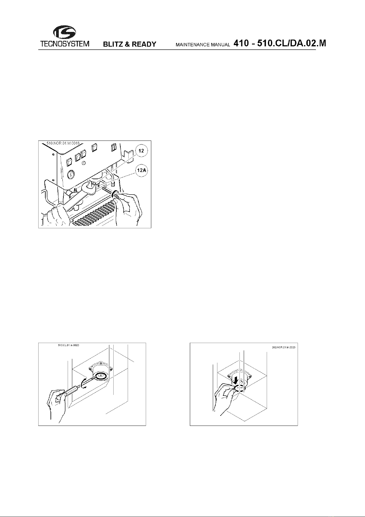
2.1 - Pod holder setting (Only for model 510)
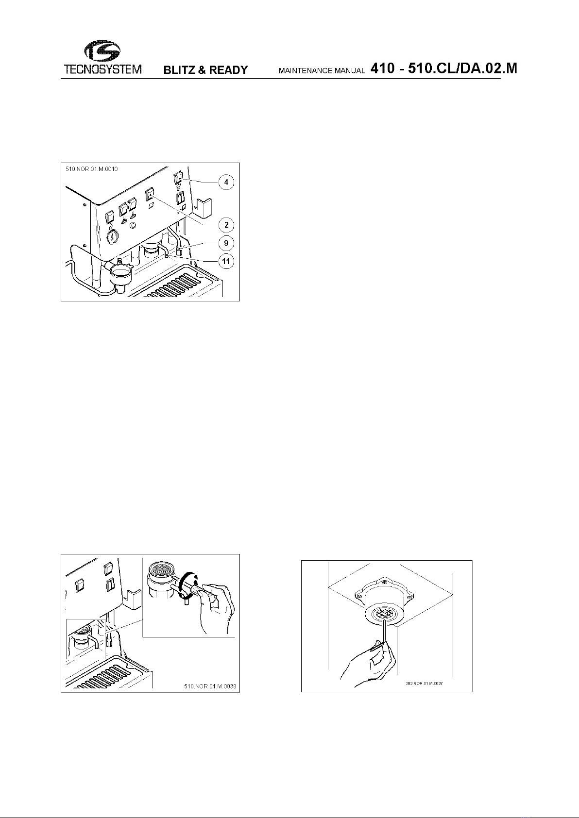
2.2 – Filter cleaning (Only for model 510)
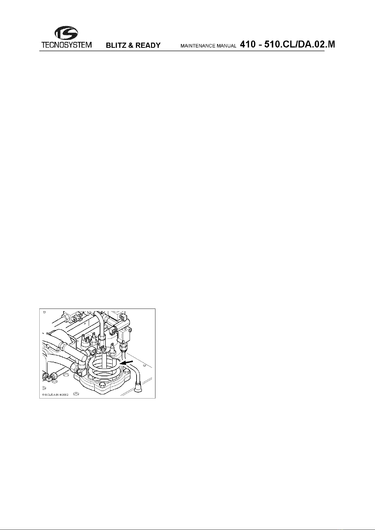
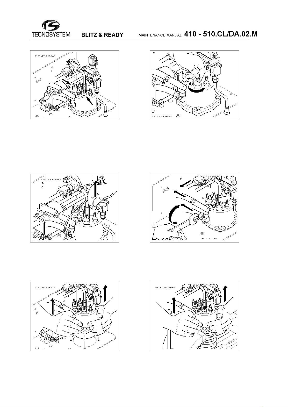
2.3 – Maintenance of the cappuccino maker
3 – Possible problems due to electro-mechanical faults
3.1 - The machine does not turn on.
3.2 - The machine turns on but does not heat.
3.3 - When you press the coffee switch, the pump goes on in a very noisy
way, but no coffee comes out of the pipe.
3.4 - When you press the coffee switch, the pump goes on but no coffee
comes out of its spout and water comes out of the hot water pipe.
3.5 - When you press the water delivery button, the pump goes on, but the
water exits through the by-pass instead of coming out from the relevant pipe,
and goes into the tank (short pipe).
3.6 - When you press the coffee delivery button, the pump goes on but does
not let any coffee out from the relevant pipe.
3.7 - During the steam boiler water level renewal phase, the pump goes on
working for a maximum time of 2 minutes, leading to safety stopping of the
machine.
3.8 - Continuous dripping from the coffee spout when the machine is on,
even when it is not working.
3.9 – When you press the water or coffee switch, the pump is not turned
on.
3.9A - The machine makes the automatic differential switch intervene in
order to protect the power line it is connected to.
3.10 - Steam boiler pressure fault.
3.11 - The steam boiler does not heat.
3.12 - Fault with steam output during working phase.
3.13 - Faulty water output from the safety valve of the boiler during
coffee delivery phase.
3.14 – If steam delivery is requested, the pressure switch shows zero
pressure and the steam delivery stops immediately.
4 - Problems, diagnostics and instructions about the station, the
keyboard and the dosing of the DA model.
4.1 - When turning the machine on, the leds on the keyboard stay off, without
performing the turning on/off sequence.
4.2A - When selecting a coffee (high or low coffee level), a quantity of coffee
different from the preset one is obtained.