TECNOTER LQMI Series User manual

LQMI
LQMI
H
HYDRAULIC
YDRAULIC
MAGNET
MAGNET
V
VER
ER: T
: T
LQMI35
LQMI35
LQMI45
LQMI45
LQMI55
LQMI55
LQMI60
LQMI60
LQMI70
LQMI70
Division: Tecnoter srl Hyd. Magne LQMI Ver. T Page 1/38 Rev: 1.0a_En –
15/07/2018

INDEX
0 INTRODUCTION 3
0.3 SCOPE OF THE INSTRUCTION MANUAL 3
0.4 HOW TO READ THE INSTRUCTION MANUAL 3
0.5 HOW TO STORE THE INSTRUCTION MANUAL 4
0.6 HOW TO UPDATE THE INSTRUCTION MANUAL 4
0.7 RECIPIENTS 4
0.8 GLOSSARY AND SYMBOLS 5
0.8.1 GLOSSARY 5
0.8. SYMBOLS 6
1 GENERAL INFORMATION 7
1. MANUFACTURER IDENTIFICATION AND TECHNICAL SUPPORT 7
1.3 MACHINE IDENTIFICATION DATA AND PLATES 7
1.4 DECLARATION OF CONFORMITY 8
1.5 CUSTOMER/USER RESPONSIBILITIES 9
TECHNICAL DESCRIPTION 11
.3 COMPOSITION OF THE BATTERY MAGNET SYSTEM 11
.4 DESCRIPTION OF THE HYDRAULIC MAGNET 1
.4.1 POWER SYSTEM OF THE HYDRAULIC MAGNETIC PLATE 1
.4. TECHNICAL DATA HYDRAULIC MAGNETS 13
.5 FACTORS AFFECTING THE FORCE OF ATTRACTION OF MAGNETS 13
3 SAFETY 15
3. GENERAL SAFETY WARNINGS 15
3. .1 GENERAL REQUIREMENTS 15
3. . CHECKS & INSPECTIONS 15
3.3 INTENDED USE STANDARD VERSION 15
3.4 INTENDED USE T VERSION 15
3.5 REASONABLY FORESEEABLE MISUSE 15
3.6 DANGER ZONES 16
3.7 SAFETY DEVICES 17
3.8 SIGNS AND DECALS 18
3.9 RESIDUAL RISKS 18
3.10 OPERATING ENVIRONMENT CONDITIONS 19
3.10.1 LIGHTING 19
3.10. VIBRATIONS 19
3.10.3 SOUND EMISSIONS 20
4 MAGNET INSTALLATION 21
4. TRANSPORTATION AND MOVING 21
4.3 STORAGE AND DISPOSAL 21
4.4 OPERATING ENVIRONMENT PREPARATION 21
4.4.1 PREPARING THE AREA FOR INSTALLATION 21
4.4. MACHINE AND HYDRAULIC SYSTEM PREPARATION 22
4.5 PRELIMINARY CHECKS OF MECHANICAL UNITS, ELECTRICAL CONNECTIONS AND INSPECTION
OF SAFETY SYSTEMS 23
5 USING THE MAGNET 24
5.1 GENERAL INFORMATION 24
5. INSPECTIONS 24
5. .1 VISUAL CHECKS 24
5. . INTRODUCTION OF ENERGIES AND POWER ON THE MACHINE 24
5. .3 FUNCTIONAL TESTING 25
5.3 OPERATIONS 25
5.3.1 COMMISSIONING 25
5.3. WORKING CYCLE 25
5.3.3 REQUIREMENTS FOR CORRECT USE 26
5.3.4 ENVIRONMENTAL CONDITIONS 27
5.3.5 LOADS PERMITTED 27
5.3.6 EQUIPMENT AT REST 27
5.3.7 GENERAL MALFUNCTIONING 27
Division: Tecnoter srl Hyd. Magne LQMI Ver. T Page 2/38 Rev: 1.0a_En –
15/07/2018

6 MAINTENANCE 30
6. PRECAUTIONS 30
6.3 PERIODIC MAINTENANCE 30
6.4 LUBRICATION AND CLEANING 30
6.5 LAYOUT, ADJUSTMENTS AND REPLACEMENT OF COMPONENTS 31
6.5.1 ADJUSTMENT AND REPLACEMENT OF THE HYDRAULIC CONTROL VALVE (HCV) 31
6.6 REPLACEMENT OF MAIN COMPONENTS 35
6.6.1 REPLACEMENT OF THE HYDRAULIC MOTOR 35
6.6. REPLACEMENT OF THE COMPLETE ELASTIC COUPLING 35
6.6.3 REPLACEMENT OF THE THREE-PHASE GENERATOR 36
6.6.4 REPLACING THE ELECTRONIC POWER SUPPLY 36
6.7 MAINTENANCE SHEET 37
NOTE: POINTS 0.1 AND 0.2 ARE VOLUNTARY OMISSED
Division: Tecnoter srl Hyd. Magne LQMI Ver. T Page 3/38 Rev: 1.0a_En –
15/07/2018

0 INTRODUCTION
0.3 SCOPE OF THE INSTRUCTION MANUAL
These nstruct ons are an ntegral part of the mach ne and are ntended to prov de all nformat on necessary for:
1. Proper awareness of all safety concerns;
2. How to safely handle the mach ne, packaged and unpackaged;
3. Proper nstallat on of the scrap magnet;
4. In-depth knowledge of ts operat on and l m ts;
5. Its correct use n safe cond t ons;
6. Perform ma ntenance, properly and safely;
7. D smantle the mach ne safely and n compl ance w th ex st ng laws to protect the health of workers and the env ronment.
Attention! Superv sors at the locat on where th s equ pment w ll be nstalled have an obl gat on to read the contents
of th s document and to ensure operators and ma ntenance workers read the parts of t that apply to them.
Th s document assumes that the current work health and safety laws are followed n shops where the equ pment w ll be nstalled.
The nstruct ons, draw ngs and documentat on conta ned n th s manual are techn cal n nature and are the property of the manufacturer and
may not be reproduced n any manner, n whole or n part.
0 INTRODUCTION
0.4 HOW TO READ THE INSTRUCTION MANUAL
The manual s d v ded nto autonomous chapters, each of wh ch s targeted to a spec f c type of operator ( nstaller, operator, and ma ntenance
techn c an), for whom the sk lls needed to operate the mach ne safely have been def ned.
The word "hydraulic magnet" is sometimes replaced with "machine", "equipment" or "interchangeable equipment".
The sequence of the chapters corresponds to the l fe of the mach ne.
To make t easy to understand, terms, abbrev at ons, and symbols were used. The r descr pt ons are prov ded later n th s chapter.
The nstruct on manual s compr sed of a cover, table of contents, and a ser es of chapters/sect ons (w th chapter t tles n black and chapter
subsect on n red).
In the contents of the nd v dual paragraphs, the t tle of the chapter w ll be repeated w th ts paragraph n red
Example
The cover page shows the mach ne dent f cat on data, model, and ser al number and a photograph/draw ng of the type of mach ne descr bed.
Figure numbering
Each f gure s numbered and identified by the chapter no. and the sequential figure no.
Example fig. .3 corresponds to f gure no. 3 n Chapter 2
Table numbering
Each table s numbered and identified by the chapter no. and the sequential table no.
Example tab. 3.4 corresponds to table no. 4 n Chapter 3
Units of measure
The un ts of measure are g ven us ng the nternat onal system.
Division: Tecnoter srl Hyd. Magne LQMI Ver. T Page 4/38 Rev: 1.0a_En –
15/07/2018

0 INTRODUCTION
0.5 STORING THIS INSTRUCTION MANUAL
Th s nstruct on manual must be carefully stored and must accompany the mach ne whenever t changes hands.
It must be handled carefully, w th clean hands, and t must not be placed on d rty surfaces.
No parts must be removed, torn, or changed.
It must be stored n areas protected from hum d ty and heat.
0 INTRODUCTION
0.6 HOW TO UPDATE THE INSTRUCTION MANUAL
The manufacturer reserves the r ght to change the des gn and make mprovements to the mach ne w thout commun cat ng them to the
customer and w thout updat ng the manual that has already been del vered to the user.
0 INTRODUCTION
0.7 INTENDED RECIPIENTS OF THE INSTRUCTION MANUAL
Th s manual s ntended for:
The operator - understood as the person respons ble for operat ng, adjust ng, clean ng, and perform ng rout ne ma ntenance on the mach ne.
Skilled personnel or skilled operator - understood as those nd v duals who have attended spec al zat on courses, tra n ng, etc. and have
exper ence n nstallat on, comm ss on ng and ma ntenance, repa rs, and transport of the mach ne.
Exposed individuals - understood as those nd v duals whose presence ns de and/or near a mach ne s a r sk to the r own health or safety.
Qualifications of the intended recipient
The mach ne s ntended for profess onal and not general use and therefore ts use may only be entrusted to qual f ed nd v duals who, n
part cular:
1. Are legal adults;
2. Are phys cally and mentally f t to perform operat ons of part cular techn cal d ff culty;
3. Have been adequately tra ned n operat ng and ma nta n ng the mach ne;
4. Are cons dered by the r employer su table to perform the task they have been ass gned;
5. Are capable of understand ng and nterpret ng the operator manual and safety precaut ons;
6. Are knowledgeable of the emergency procedures and how to mplement them;
7. Have the ab l ty to use the spec f c type of equ pment;
8. Are fam l ar w th the spec f c appl cable regulat ons;
9. Have understood the operat ng procedures def ned by the manufacturer of the mach ne.
0 INTRODUCTION
0.8 GLOSSARY AND SYMBOLS
Th s paragraph l sts unusual terms or those whose mean ng s d fferent than usual.
The paragraph that follows expla ns the abbrev at ons used and the mean ng of the symbols used to nd cate the operator qual f cat on and
mach ne status. The r use allows qu ck and clear nformat on on the correct and safe use of the mach ne.
0INTRODUCTION
0.8 GLOSSARY AND SYMBOLS
0.8.1 GLOSSARY
MACHINE: n th s manual, mach ne refers to the hydraul c magnet pursuant to D rect ve 2006/42/EC.
DANGER ZONE: any area ns de and/or near a mach ne n wh ch the presence of a person const tutes a r sk to the safety and health of sa d person
(Annex , 1.1.1 D rect ve 2006/42/EC)
EXPOSED PERSON: any person who s found part ally or ent rely n a danger zone
Division: Tecnoter srl Hyd. Magne LQMI Ver. T Page 5/38 Rev: 1.0a_En –
15/07/2018

OPERATOR: the person or persons respons ble for nstall ng, operat ng, regulat ng, perform ng ma ntenance, clean ng, repa r ng, or transport ng
a mach ne (Annex , 1.1.1 D rect ve 2006/42/EC)
MAN-MACHINE INTERACTION: any s tuat on n wh ch an operator must nteract w th the mach ne n any operat ng phase and any moment of ts
l fe
OPERATOR QUALIFICATION: m n mum level of sk lls that the operator must have to perform the operat on descr bed
NUMBER OF OPERATORS: m n mum number of operators needed for perform ng the operat on descr bed and der v ng from an attent ve analys s
performed by the manufacturer. The use of a d fferent number of persons could jeopard se the expected result or put the nd v duals nvolved
n danger.
RESIDUAL RISK: r sk that has not been poss ble to el m nate or suff c ently reduce through des gn, aga nst wh ch the protect ons are not (or are
not totally) effect ve; the manual g ves nformat on regard ng t and nstruct ons and warn ngs to overcome t (see, respect vely, 5.4 and 6.5.1 of
European standards EN 12100: 2010).
SAFETY COMPONENT: t s a component used to ensure safe operat on and whose fa lure or poor operat on jeopard zes the safety and/or the
health of the exposed nd v duals (e.g., l ft ng equ pment; f xed, mob le and adjustable guards, electr c, electron c, opt cal, pneumat c and
hydraul c dev ces that nterlocks a protector, etc.).
CAUTION!
The descr pt ons preceded by th s symbol conta n very mportant nformat on and requ rements, part cularly
regard ng safety.
Fa lure to comply can result n:
1. Danger to the operators;
2. Loss of the contractual warranty;
3. Loss of manufacturer respons b l ty.
0 INTRODUCTION
0.8 GLOSSARY AND SYMBOLS
0.8. SYMBOLS
SYMBOLS RELATED TO OPERATOR QUALIFICATION TAB 0.1
Symbol Description
OPERATOR: nd v dual capable of runn ng the mach ne us ng the commands on the push button panel, load and
unload the mater als used dur ng work and s mple start-up or recovery funct ons follow ng forced stops. Th s
nd v dual must have full knowledge of the nstruct ons n the mach ne use and ma ntenance manual.
LIFTING AND HANDLING EQUIPMENT OPERATOR: operator qual f ed to use equ pment for l ft ng and handl ng
mater als and mach nes (closely follow ng the manufacturer's nstruct ons) accord ng to current laws n the
country where the mach ne s used.
MECHANICAL MAINTENANCE TECHNICIAN: qual f ed techn c an capable of runn ng the mach ne n normal cond t ons,
operat ng on mechan cal parts to perform all adjustments, ma ntenance ntervent ons, and repa rs as necessary.
Not qual f ed for ntervent ons on the electr cal system w th voltage. Possesses any mach nery keys used to d sable
the safety dev ces. Th s nd v dual must have full knowledge of the nstruct ons n the mach ne use and
ma ntenance manual.
Division: Tecnoter srl Hyd. Magne LQMI Ver. T Page 6/38 Rev: 1.0a_En –
15/07/2018

ELECTRICAL MAINTENANCE TECHNICIAN: qual f ed techn c an capable of runn ng the mach ne under normal
cond t ons and all electr cal operat ons for adjustments, ma ntenance, and repa rs. Can also test the mach ne
operat ng cycle. Not qual f ed to work n the presence of voltage ns de cab nets and sw tch boxes; not qual f ed for
mechan cal ntervent ons. Possesses any mach nery keys used to d sable the safety dev ces. Th s nd v dual must
have full knowledge of the nstruct ons n the mach ne use and ma ntenance manual.
MANUFACTURER TECHNICIAN: qual f ed techn c an made ava lable by the manufacturer of the nd v dual
components to carry out compl cated operat ons n part cular s tuat ons or as agreed w th the user. The r sk lls
depend on the s tuat on and are mechan cal, electr cal, electron c, or n software.
SYMBOLS RELATED TO SAFETY TAB 0.
DANGER! INDICATES A DANGER OR RISK OF
INJURY OR DEATH TO THE USER. PAY
MAXIMUM ATTENTION TO THE TEXT WITH
THIS SYMBOL.
ATTENTION! INDICATES A WARNING OF
POSSIBLE DETERIORATION OR DAMAGE TO
THE INTERCHANGEABLE EQUIPMENT.
PAY ATTENTION TO TEXT WITH THIS SYMBOL.
DANGEROUS VOLTAGE HOT SURFACES
DO NOT REMOVE THE SAFETY DEVICES. IT IS FORBIDDEN TO CLEAN, OIL, GREASE, AND
REPAIR OR ADJUST MOVING PARTS BY HAND.
SAFETY SHOES ARE REQUIRED. PROTECTIVE OVERALLS REQUIRED.
PROTECTIVE GLOVES REQUIRED. PROTECTIVE GOGGLES REQUIRED.
THE SYMBOLS IN A TRIANGLE INDICATE A HAZARD.
THE SYMBOLS IN A CIRCLE INDICATE A REQUIREMENT/PROHIBITION.
Division: Tecnoter srl Hyd. Magne LQMI Ver. T Page 7/38 Rev: 1.0a_En –
15/07/2018
!

1 GENERAL INFORMATION
1. MANUFACTURER IDENTIFICATION AND TECHNICAL SUPPORT
ELECTRICAL, HYDRAULIC, AND BATTERY ELECTROMAGNETS are serv ced all over the world w th d rect coord nat on and Tecnoter techn cal
support.
For any nformat on or clar f cat on regard ng the r use, ma ntenance, nstallat on, etc., Tecnoter’s serv ce department or your local dealer
are always ava lable to answer the purchaser's quest ons.
The purchaser should make any requests n clear terms, referr ng to th s manual and always g v ng the data wr tten on the mach ne
dent f cat on plate.
Any request for support at the customer's prem ses or clar f cat on regard ng techn cal aspects n th s document must be addressed to the
manufacturer or to your local dealer.
1 GENERAL INFORMATION
1.3 MACHINE IDENTIFICATION DATA AND PLATES
Sect on related to mach nery for Eu market only
Division: Tecnoter srl Hyd. Magne LQMI Ver. T Page 8/38 Rev: 1.0a_En –
15/07/2018

1 GENERAL INFORMATION
1.5 CUSTOMER/USER RESPONSIBILITIES
1. Make sure the work area s compl ant w th the safety requ rements set forth n current leg slat on n the country where the electromagnet s used.
2. Make sure all of the work equ pment made ava lable to the operators s compl ant w th the safety requ rements set forth n current leg slat on n the
country where the l ft ng system s nstalled and used.
3. Make sure the hydraul c power supply s compl ant w th what s requ red by the manufacturer (see techn cal spec f cat ons).
4. Before nstall ng, us ng, or perform ng ma ntenance on the hydraul c magnet, make sure the nd v duals who w ll carry out these operat ons have
read and understood the use and ma ntenance manual. In part cular, make sure all safety requ rements and requ rements for correct ma ntenance
and safe use are thoroughly understood.
5. Make sure the operator who w ll use the equ pment has been adequately nstructed for safe use of the equ pment nstalled on the work ng veh cle
on wh ch t w ll be nstalled w thout creat ng hazardous s tuat ons.
6. Make sure the nstallat on and ma ntenance personnel have the proper techn cal sk lls to perform those act v t es and are appropr ately nstructed.
7. It s the user/customer's respons b l ty to observe and carefully follow the nstruct ons conta ned n th s manual n order to max m ze product v ty as
well as prolong the l fe of the equ pment and espec ally to reduce the exposure to r sk of those nd v duals who w ll use and ma nta n the
nterchangeable equ pment suppl ed.
Attention!
It s the customer/user's respons b l ty to attach the nstruct ons conta ned here n w th the use and ma ntenance
manual for the system/overall assembly and/or any safety requ rements n the country where t s used and
prov de the operator and ma ntenance techn c an w th any add t onal nformat on.
Division: Tecnoter srl Hyd. Magne LQMI Ver. T Page 9/38 Rev: 1.0a_En –
15/07/2018

TECHNICAL DESCRIPTION
.3 COMPOSITION OF THE HYDRAULIC MAGNETS
Operating Principle
The hydraul c electromagnet s a p ece of equ pment used for the movement of ferrous mater al, n part cular for the
movement of ferrous scrap metals ntended for mater al recycl ng. The hydraul c electromagnet s des gned for nstallat on on
mach nes equ pped w th an aux l ary hydraul c c rcu t, for example excavators veh cles w th hydraul c cranes, etc.
Hydraul c power s der ved from the serv ce l nes of the hydraul c c rcu t of the mach ne, to wh ch the electromagnet must be
connected. In part cular, the power c rcu t l ne of the hydraul c hammer or the rotat on of adequate power s su table for the
hydraul c connect on.
The hydraul c electromagnet uses the hydraul c power suppl ed by the c rcu t of the mach ne us ng a hydraul c motor coupled w th a
synchronous alternator that generates the electr c ty used to power the magnet.
The hydraul c electromagnet does not have ts own controls. It s brought to full power by act vat ng the hydraul c flow n the c rcu t
to wh ch t s connected (for example, v a an act vat on pedal or button to act vate the hydraul c hammer).
The cond t on of "magnet zat on" or "demagnet zat on" of the hydraul c magnet only develops through the movement or non-
movement of the hydraul c o l under pressure. Adequate hos ng connects the hydraul c force po nts between the mach ne and the
hydraul c magnet.
The electron c power c rcu t on board prov des two poss b l t es.
A) Standard: cons sts of an overs ze power supply that, thanks to ts d scharge res stance, prevents dangerous surges that are
generated at the t me of demagnet zat on.
B) Opt onal c rcu t w th nsulated-gate b polar trans stor (IGBT) w th a h gh-power trans stor, a dev ce that prevents dangerous
surges that are generated at the t me of demagnet zat on, and an electron c c rcu t that generates a polar ty reversal due to the
rap d demagnet zat on of the magnet.
The hydraul c electromagnet and the l ft ng cha ns are ncluded n the standard supply of the mach ne.
The mechan cal connect on of the magnet to the mach ne takes place through three-arm cha n w th central arms; the max mum
capac ty of the system s 11,000 kg.
The end-user can dec de to replace the cha ns w th other systems of attach ng to the mach ne, for example qu ck coupl ngs. It s the
respons b l ty of the end user to ensure compl ance w th the requ rements of law and regulat ons of the attachment system
adopted, and also ver f cat on of the adaptab l ty w th ts own funct ons and the features of a spec f c model.
The hydraul c magnet n the vers on w th teeth s always suppl ed w th a cover equ pped w th a dr lled plate for attach ng a
bracket.
The bracket must be f rmly f xed to the magnet welded plate by means of screws / bolts of adequate s ze
The coupl ng of the excavator to the magnet s made through the bracket, as for other common types of equ pment.
Division: Tecnoter srl Hyd. Magne LQMI Ver. T Page 10/38 Rev: 1.0a_En –
15/07/2018
TECHNICAL DESCRIPTION
.4 DESCRIPTIONS OF THE HYDRAULIC MAGNETS
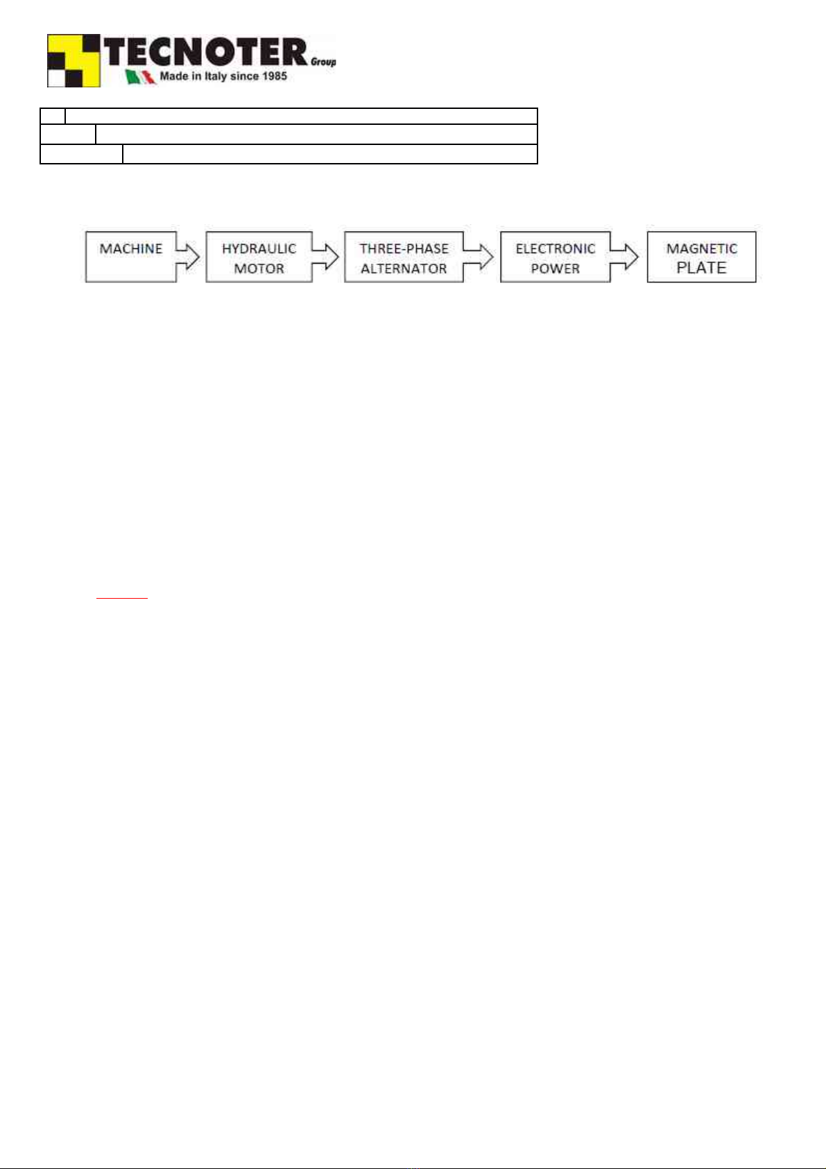
.4.1 POWER SYSTEM OF THE HYDRAULIC MAGNETIC PLATE
Energy s prov ded by the mach ne’s hydraul c system on wh ch the magnet c l ft ng system has been nstalled.
The hydraul c motor s act vated when o l s sent to the c rcu t v a the control lever. When the hydraul c motor rotates, the three-phase
alternator produces electr c ty that s sent to the electron c power supply un t. By means of an alternate/cont nuous power convers on,
the electron c un t transforms the electr c ty n nput nto energy that s su table to power the magnet c plate, that then generates the
magnet c f eld requ red to attract the ferromagnet c parts.
Operation Process
1. The operator n the cab n of the mach ne act vates the hydraul c magnet lever, wh ch sends o l through the hydraul c l ne towards the
hydraul c magnet.
2. Upon arr val at the hydraul c magnet, the o l turns the hydraul c motor.
3. The hydraul c motor turns the current generator that sends voltage to the electron c control box.
4. The electron c control box evaluates the ncom ng voltage and f t dec des that the voltage value (> 80V nput nto the electron c
control) s suff c ent, then t transfers electr c ty to the magnet c plate wh ch becomes magnet zed, attract ng ferromagnet c mater al.
5. If the electron c control cons ders the voltage nsuff c ent t does not send electr c ty to the magnet c plate.
6. To keep the magnet magnet zed, t s essent al to cont nue operat on from the cab n.
7. If the operator nterrupts operat on from the cab n, the motor-generator no longer sends voltage to the electron c control, and the
magnet w ll be demagnet zed.
DANGER !
Demagnet zat on may happen for other reasons related to a decrease n hydraul c performance (flow and/or pressure) of the mach ne.
For example, the s multaneous use of several hydraul c serv ces or the loss of revolut ons of the mach ne could lead to a drop of o l flow-
pressure to the hydraul c magnet. Th s can reduce the revolut ons of the hydraul c motor, thus reduc ng the revolut ons speed of the
generator and also reduc ng the voltage sent to the electron c control.
If the hydraul c var at ons are s gn f cant, the electron c control may nterpret these changes n voltage as a command to stop
magnet zat on. For th s reason, t s adv sable to use an ndependent and/or permanent serv ce for the operat on of the hydraul c magnet
that never falls below the m n mum values requ red.
Division: Tecnoter srl Hyd. Magne LQMI Ver. T Page 11/38 Rev: 1.0a_En –
15/07/2018

TECHNICAL DESCRIPTION MAGNETS
.4 DESCRIPTION OF THE HYDRAULIC MAGNETS
.4. TECHNICAL DATA HYDRAULIC MAGNETS
T
A B
. . LQMI35 LQMI45 LQMI55 LQMI60 LQMI70
WEIGHT HYDRAULIC MAGNET KG
LBS
750
1650
910
2000
1050
2310
1300
2850
1500
3300
WEIGHT HYDRAULIC MAGNET T VERSION KG
LBS
900
1980
1190
2620
1380
3050
1545
3400
2050
4500
MINIMUM FLOW RATE REQUIRED (*) L/1’
Gallon
L/1’
Gallon
45
12
50
13
200
53
70
18
200
53
80
21
200
53
100
26
200
53
MAXIMUM FLOW RATE (***) 200
53
MINIMUM PRESSURE REQUIRED (**)
BAR
PSI
180
2610
180
2610
180
2610
180
2610
180
2610
MAX RETURN PRESSURE
BAR
PSI
20
290
20
290
20
290
20
290
20
290
MAXIMUM PRESSURE
BAR
PSI
240
3500
240
3500
240
3500
240
3500
240
3500
APPROXIMATE HYDRAULIC MOTOR-GENERATOR REVOLUTIONS REV PER
MINUTE
2350-
2400
2480-
2500
2490-
2510
2500-
2540
2580-
2620
THREE-PHASE VOLTAGE TO THE TERMINALS OF THE GENERATOR VOLTS
180 180 180 180 180
POWER DELIVERED FROM THE GENERATOR
KW 3.5 4.5 5.5 6 7
DIAMETER MAGNETIC PLATE
mm
INCHES
860
34
950
38
1050
42
1130
45
1250
50
THEORETICAL RESISTANCE MAGNETIC PLATE AT 20°
Ώ
13.8 10.7 8.8 8 6.9
THEORETICAL VOLTAGE TO THE MAGNETIC PLATE
Vcc
220 220 220 220 220
THEORETICAL CURRENT INTENSITY TO THE MAGNETIC PLATE
Amp
15.9 20.5 25 27.2 31.8
THEORETICAL POWER DELIVERED FROM THE PLATE
KW
3.5 4.5 5.5 6 7
CHAIN MAXIMUM LIFTABLE LOAD KG
SHORT TON
7,000
7.710
9,000
9.920
9,000
9.920
9,000
9.920
9,000
9.920
CARRIER WEIGHT TON 10 – 14 14 – 17 19 – 23 20 – 25 26 - 32
ATTENTION!
For the operat on of the magnet, t s adv sable to use an ndependent hydraul c c rcu t.
Th s results n:
1. Less energy consumed (lower o l flow)
2. Less heat ng of the mach ne’s o l
3. Reduced chance of unwanted mater al fall because of sudden drop of o l flow.
Th s can happen when another hydraul c serv ce s used at the same t me as the magnet, n a common c rcu t.
(*) M n mum flow rate requ red = m n mum flow rate requ red at any t me. If the flow rate falls below th s value even for a short wh le, there w ll be a loss of load.
For th s reason we suggest to set the carr er for a flow h gher than the m n mum to compensate flow fluctuat ons. If the carr er has reduced flow fluctuat ons we
suggest to set the pump at 20-30 l ters per m nute over the m n mum value. If the carr er has large flow fluctuat ons we suggest 70-80 l ters per m nute over the
m n mum value. Typ cal pump sett ng for an lqm 45 w th med um flow fluctuat ons s 200bar and 100 l ters per m nute.
(**) Th s s the value the pump must grant n correspondence wth the nomnal flow. Therefore the sett ng value of the excavator pressure must be cal brated to a h gher value
than that requ red, normally around an add t onal 20 bar, to compensate for any losses for heat ng.
(***) Max mum flow rate that must never be exceeded
ATTENTION!
Us ng the magnet at max mum capac ty value for long per ods may result n over-heat ng.
Division: Tecnoter srl Hyd. Magne LQMI Ver. T Page 12/38 Rev: 1.0a_En –
15/07/2018

TECHNICAL DESCRIPTION MAGNETS
.5 FACTORS AFFECTING THE FORCE OF ATTRACTION OF MAGNETS
In order to optimize lifting of the load, the following factors must be taken into consideration:
Con t
act s ur f
ace
The greater the surface area w th wh ch the magnet comes nto contact w th the p ece to be l fted, the greater the force w th wh ch the p ece tself s l fted.
S u pe
r fi
c i
al f i
n i
s h
A good surface of contact w th the magnet c l fter cons derably d m n shes the gaps (the empty spaces between the magnet and mater als) thus obta n ng a
cons stent force of magnet c anchorage.
M
a te
r i
al
The l ft ng mater al must be a magnet c conductor. Mater al w th the h ghest conduct v ty s m ld steel (ferromagnet c), wh le the worst s alum num
(d amagnet c).
Below are the reduct on factors of the performance depend ng on the type of mater al:
MATERIAL TO LIFT REDUCTION FACTOR FOR THE FORCE OF ATTRACTION
LOW CARBON SOFT STEEL 1
STEEL CASTING 0.9
SILICON STEEL (m n. 3%) 0.8
STEEL WITH HIGH CARBON AND/OR ALLOY 0.7
CAST IRON 0.45
NICKEL 0.
STAINLESS STEEL, NON-MAGNETIC, BRASS, ALUMINUM 0
Division: Tecnoter srl Hyd. Magne LQMI Ver. T Page 13/38 Rev: 1.0a_En –
15/07/2018

3 SAFETY
3. GENERAL SAFETY WARNINGS
3. .1 GENERAL REQUIREMENTS
All the safety equ pment located on the mob le elements to prevent acc dents and protect safety cannot be mod f ed or removed and must
always be adequately safeguarded.
The user must mmed ately nform the employer or h s d rect super or of any defect or anomal es n the mob le elements.
3 SAFETY
3. GENERAL SAFETY WARNINGS
3. . CHECKS & INSPECTIONS
Parts subject to wear must be checked as nd cated n the spec f c chapter n th s manual.
Whenever parts that are worn or defect ve are not replaced n a t mely manner, the manufacturer shall not be l able for any damages
from acc dents that could occur.
Inspect ons must be performed by experts and they must be v sual and funct onal n order to ensure the safety of the mach ne. They
nclude:
1. Inspect on of all structures, wh ch must not show any cracks, breakage, damage, deformat on, corros on, wear or alterat ons
compared to the r or g nal character st cs;
2. Inspect on of all mechan cal organs;
3. Inspect on of all the safet es nstalled;
4. Inspect on of all the connect ons w th p ns and screws;
5. Operat onal nspect on of the mach ne;
6. Inspect on of the mach ne cond t on.
CAUTION! If any anomal es are detected, they must be el m nated before operat ng the mach ne and the expert who performs the
nspect on must note the repa r on the card, thus g v ng approval for use of the mach ne.
The results of th s nspect on must be reported on a card.
If the person perform ng the nspect on f nds cracks or dangerous anomal es, he must mmed ately not fy the mach ne manufacturer.
Put the mach ne out of serv ce whenever there are operat ng anomal es and perform all nspect ons and/or repa rs.
In order to ensure max mum safety when handl ng the mach ne, the follow ng s proh b ted:
1. Tamper ng w th parts of the mach ne;
2. Us ng the mach ne when not operat ng at complete eff c ency;
3. Mod fy ng the mach ne to change the or g nally establ shed use w thout the express author zat on of the manufacturer or w thout
assum ng complete respons b l ty.
3 SAFETY
3.3 INTENDED USE ILQMI STANDARD VERSION
The hydraul c magnet s des gned to l ft ferromagnet c mater als when nstalled on truck cranes, self-propelled loaders, excavators, forkl fts,
etc.
It is for professional use only.
It s ntended to be used by a person n possess on of knowledge and exper ence n the use of systems of th s type, w thout l m tat ons n
phys cal and mental capac ty, and w th no s ght damage.
3 SAFETY
3.4 INTENDED USE ILQMI-T VERSION
The ILQMI-T vers on ncludes the presence of teeth n add t on to the hydraul c magnet. The magnet can therefore be used to l ghtly d g on
loose surfaces n order to f nd h dden or bur ed p eces of metal. It can also be used to m x mater als such as ferrous metals and crushed
concrete.
The T vers on absolutely cannot be used as a means of d gg ng as a bucket. Pressure and stress from the excavator arm are so strong, they
w ll damage the magnet mmed ately.
Division: Tecnoter srl Hyd. Magne LQMI Ver. T Page 14/38 Rev: 1.0a_En –
15/07/2018

3 SAFETY
3.5 REASONABLY FORESEEABLE MISUSE
The act ons descr bed below, wh ch obv ously cannot cover the ent re range of "IMPROPER USE" poss b l t es for the system and are those that are
reasonably foreseeable, must be cons dered to be absolutely proh b ted and therefore are forb dden.
THE HYDRAULIC MAGNET MUST NOT BE USED FOR ANYTHING OTHER THAN THOSE SET FORTH IN THE "INTENDED USE" SECTION and therefore IT IS
FORBIDDEN to use t n cond t ons other than those ment oned and n part cular:
In explos ve or corros ve atmospheres or atmospheres w th a h gh concentrat on of dust or o ly substances suspended n the a r.
W th safety dev ces excluded or not operat ng.
W th hydraul c suppl es that are d fferent than what s nd cated.
As a walk ng area or storage area for other tems.
In cond t ons w th a low level of safety for the operator or other nd v duals;
In the event of tamper ng;
If a v sual nspect on shows damage to the magnet or a malfunct on;
For mov ng people;
For l ft ng and mov ng loads other than those der v ng from the effect of magnet zat on;
By operators who are not qual f ed or who have not read, understood and learnt the contents of the manual;
Do not use T vers on magnets to d g n hard ground.
IT IS ALSO FORBIDDEN:
To use the magnet w thout per od c ma ntenance hav ng been performed
To use the magnet w th lack of concentrat on or carelessly. Th s conduct can lead to ser ous acc dents.
To use the magnet when n a hurry der v ng from the pressure to ma nta n the magnet n operat on n all c rcumstances. Th s conduct can create
potent ally non-compl ant work cond t ons.
To use the magnet when there are people, equ pment or veh cles n the mmed ate area.
Division: Tecnoter srl Hyd. Magne LQMI Ver. T Page 15/38 Rev: 1.0a_En –
15/07/2018

3 SAFETY
3.6 DANGER ZONES
The danger zone s def ned as all of the area around the work ng veh cle.
For a deta led v ew of the area, refer to the manual for the work ng veh cle on wh ch the equ pment s nstalled.
It s forb dden to be n the danger zone and n the work ng veh cle operat ng area dur ng operat on.
DANGER! NO ONE, EXCEPT THE OPERATOR, MAY BE IN THE INTERCHANGEABLE EQUIPMENT WORK AREA.
The nterchangeable equ pment s dest ned to be used by qual f ed operators who are properly nstructed on ts use, who are aware of problems that
could occur w th l ft ng the mater als as descr bed n the "Intended use" sect on and who are consc ous of the r sks present n the work env ronment.
The nterchangeable equ pment s character zed by un ts and parts of nterchangeable equ pment that are cons dered dangerous. All of the areas
cons dered dangerous must be cordoned off n order to prevent access by unauthor zed nd v duals when the nterchangeable equ pment s n mot on.
All of the area nvolved n the work and movement of the equ pment tself s cons dered dangerous and must therefore be cordoned off.
DANGER! Post s gns forb dd ng access to the work area
DANGER! To access danger zones, operate safely and perform all operat ons and methods set forth n th s chapter and the chapters for "Installation
/ use and operation". Only author zed and spec al zed personnel may enter danger zones to perform operat ons.
Division: Tecnoter srl Hyd. Magne LQMI Ver. T Page 16/38 Rev: 1.0a_En –
15/07/2018
!
!
!
3 SAFETY
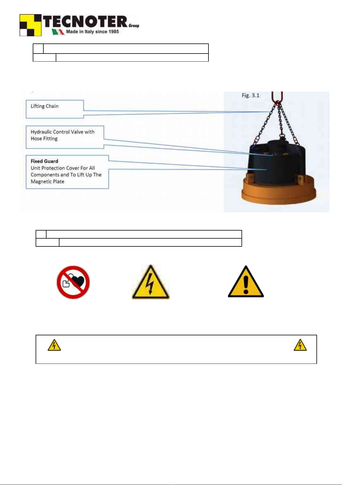
3.7 SAFETY DEVICES
The hydraul c magnet has the follow ng safety dev ces nstalled:
1. F xed Guard (protect ve cover for the power un t)
2. Hydraul c control valve
3 SAFETY
3.8 SIGNS AND DECALS
The s gns and decals nstalled on the mach ne are shown below.
Same s gns must always be reproduced and pos t oned n the work place and near the magnet c mach ne.
All data on the plates must always be leg ble and cleaned per od cally. Whenever a s gn s deter orated and/or no longer leg ble, even f only part ally,
another must be requested from the manufacturer, g v ng the data on the or g nal s gn n order to replace t.
Plates must never be removed.
Plac ng other plates on the mach ne w thout the manufacturer's consent s forb dden.
HIGH VOLTAGE Do not touch the electr c components w th n 30 m nutes from the last operat on.
Division: Tecnoter srl Hyd. Magne LQMI Ver. T Page 17/38 Rev: 1.0a_En –
15/07/2018

REMAIN AT A SAFE DISTANCE OF 0 METERS OR 65 FEET.
INTENSE MAGNETIC FIELD - PROHIBITION OF ACCESS TO BEARERS OF PACEMAKERS
ATTENTION! STICKERS
THE STICKERS MUST ALWAYS BE PRESENT ON THE MACHINE
REPLACE THEM IMMEDIATELY IF DAMAGED
DANGER! ELECTRONIC PARTS INSIDE. Do not clean with pressurized or non-pressurized jets of
water!
3 SAFETY
3.9 RESIDUAL RISKS
DEFINITION OF RESIDUAL RISK:
"R sk due to a danger that cannot be completely reduced through des gn and safety techn ques, .e., r sk due to a potent al danger that s
not obv ous."
THE FOLLOWING IS A LIST OF THE RESIDUAL RISKS AND SOLUTIONS THE USER MUST ADOPT
DANGER! FALLING LOAD
To ensure operator safety ns de the mach ne's area of operat on, t s requ red to create a zone where personnel may not pass
dur ng l ft ng operat ons.
DANGER! IMPACT AND CRUSHING
The r sk s due to the magnet's movements when hook ng the mater al to be l fted. Do not access the work zone or approach the
battery magnet dur ng operat on.
DANGER! SLIPPING Poss ble lubr cant leaks and/or res dues n the area surround ng the nterchangeable equ pment can cause those
us ng, runn ng, and ma nta n ng the battery magnet to sl p. Access these zones w th non-sl p shoes and keep the areas clean.
DANGER! FIRE The r sk s due to the poss ble presence of combust ble l qu ds between the scrap and the presence of o l from the
work ng veh cle on wh ch the equ pment s nstalled. Therefore, evaluate th s poss b l ty and equ p the work ng veh cle or battery
magnet operat ng locat on w th adequate f re ext ngu sh ng equ pment accord ng to the f re safety and prevent on laws n the
country where t s used.
DANGER! FLYING OBJECTS Th s r sk can occur dur ng the attract on phase for the ferromagnet c mater al. Th s force exerted on the
mater al could cause the project on of smaller p eces. Do not access the work zone or approach the battery magnet dur ng
operat on.
DANGER! HYDRAULIC LINE BREAK The breakage or damage of hydraul c system hoses can cause a wh pp ng effect, thereby
njur ng anyone that s located n the work area. It s essent al to perform per od c nspect ons of the hydraul c l nes and replace
anchors, hos ng, and p pes. Do not use hydraul c tubes as a foot support base.
Division: Tecnoter srl Hyd. Magne LQMI Ver. T Page 18/38 Rev: 1.0a_En –
15/07/2018
!
!
!
!
!
!
!

DANGER! WORKING VEHICLE FAILURE Due to poss ble fa lures, the safety c rcu ts on the work ng veh cle can lose the r
effect veness, lower ng the level of safety.
Therefore, you must perform per od c checks of the operat ng cond t ons of the safety dev ces on the work ng veh cle.
DANGER! INSUFFICIENT LIGHTING - There must be an adequate l ght ng system n the work areas dur ng normal operat on and
dur ng ma ntenance. The l ght ng must not create shadow areas that can cause a nu sance or d sturb ng bl nd ng l ght.
DANGER! INTENSE MAGNETIC FIELD Proh b t nd v duals w th pacemakers from pass ng near the area where
the electromagnet s used.
DANGER! ELECTRIC RISK The magnet power supply s electr c (batter es/electr c alternator). Do not open cases or
remove cas ngs. Only author zed and tra ned personnel can perform those operat ons.
3 SAFETY
3.10 OPERATING ENVIRONMENT CONDITIONS
CAUTION The hydraul c magnet cannot be used n areas w th fumes, smoke, or corros ve or abras ve dust, w th r sk of f re or
explos on and n areas where the use of explos on-proof equ pment s requ red.
THE MACHINE IS SUITABLE FOR OPERATION IN THE FOLLOWING ENVIRONMENTS:
Alt tude not greater than 3000 meters;
Temperature between -20°C and +50°C;
Relat ve hum d ty between 30% and 95%.
3 SAFETY
3.10 OPERATING ENVIRONMENT CONDITIONS
3.10.1 LIGHTING
The l ght ng n the nstallat on area must be compl ant w th current leg slat on n the company where the mach ne s nstalled and must ensure good v s b l ty
at each po nt, ensur ng not to create dangerous glare.
S nce the equ pment does not have ts own l ght source, the work area must be equ pped w th general l ght ng to ensure values between 200 and 300 lux at
every po nt of the mach ne.
ATTENTION! The hydraul c magnet must be used n an area w th su table llum nat on.
3 SAFETY
3.10 OPERATING ENVIRONMENT CONDITIONS
3.10. VIBRATIONS
Dur ng operat ng cond t ons that are compl ant w th the nstruct ons for proper use, v brat ons w ll not cause hazardous s tuat ons for the operator.
ATTENTION Excess ve v brat on can only be the result of a mechan cal fa lure wh ch must be mmed ately reported and el m nated n order to avo d
jeopard z ng the operator's safety and the ntegr ty of the hydraul c magnet.
3 SAFETY
3.10 ENVIRONMENTAL CONDITIONS
3.10.3 SOUND EMISSIONS
The cont nuous we ghted sound pressure near the magnet does not exceed 70 dB(a). The max mum c-we ghted nstantaneous sound pressure near the
hydraul c magnet does not exceed 63 pa (130 dB compared to 20 pa).
Other sound level measurements n the work env ronment must be made n accordance w th the prov s ons of the regulat ons n the country of use.
ATTENTION Refer to the use and ma ntenance manual for the work ng veh cle for any personal protect ve equ pment necessary for hear ng
protect on.
Division: Tecnoter srl Hyd. Magne LQMI Ver. T Page 19/38 Rev: 1.0a_En –
15/07/2018
!
!
!
!

4 INSTALLATION
4. TRANSPORTATION AND MOVING
No spec al equ pment s needed to unload and move the equ pment and electr cal system. The suspens on r ng must be used along w th
l ft ng equ pment w th a capac ty equal to the we ght of the magnet, as nd cated on the dent f cat on plate. For movement and transport
operat ons, the magnet must be rested and anchored to a wooden pallet to prevent sl ppage on the transport veh cle.
To unload the magnet from the transport veh cle, proceed slowly to avo d damag ng other parts. Each phase that s not performed properly
can damage the component or lead to dangerous s tuat ons for the operators.
It s recommended to use ded cated personnel and su table l ft ng equ pment and make sure that the operator s aware of these
nstruct ons.
Access to the area nvolved n the operat on must be nh b ted us ng protect ve barr ers (road barr ers).
S gns warn ng of the presence of suspended loads and access and/or passage proh b ted s gns must be posted.
Make sure the veh cles and log st c structures used are n compl ance w th the requ red use and n perfect cond t on.
DANGER! KEEP AWAY FROM HANGING LOADS!
DANGER! INSTALLATION RESTRICTION
The l fter s equ pped w th a r ng (cha n) suspens on system and therefore t can only operate f hung from a su table hook on the work ng
veh cle o r w th a r g d connect ng saddle w th the work ng veh cle.
The manufacturer shall not be l able for damages or njur es due to the use of l ft ng systems other than those descr bed.
4 INSTALLATION
4.3 STORAGE AND DISPOSAL
In the event of inactivity, the machine must be stored, adopting the following precautions:
1) Store the mach ne n a closed locat on
2) Protect the mach ne from mpacts and stresses
3) Protect the mach ne from hum d ty and sudden temperature changes
4) Prevent the mach ne from com ng n contact w th harsh substances.
When putt ng out of serv ce, for demol t on and d sposal of the mach ne or any of ts parts, the purchaser/user must follow current
leg slat on n force n the country of use. “Waste” refers to any substance and object result ng from human act v ty or natural cycles that s
abandoned or dest ned to be abandoned.
Special waste: Those result ng from ndustr al, commerc al, or art sanal process, agr cultural act v t es and serv ces that due to type or
quant ty can be ass m lated w th urban waste; deter orated and obsolete mach nery and equ pment.
Toxic waste: All wastes conta n ng or contam nated by the substances l sted n the Annex to Pres dent al Decree 915/52 mplement ng
D rect ves 75/442/EEC, 76/403/EEC and 78/319/EEC.
For used oil, follow Directive 75/439 that forbids:
Any d scharge of waste o ls nto nland surface water, ground water, coastal waters, and dra nage systems;
Any depos t and/or d scharge of used o ls that are harmful to the so l and any uncontrolled d scharge of res dues result ng from
the process ng of used o ls;
FOR THE DISPOSAL OF SPECIAL AND TOXIC WASTES, SPECIALIZED/AUTHORIZED COMPANIES MUST BE
USED.
Division: Tecnoter srl Hyd. Magne LQMI Ver. T Page 20/38 Rev: 1.0a_En –
15/07/2018
!
!
This manual suits for next models
5
Table of contents
Other TECNOTER Water Pump manuals


Popular Water Pump manuals by other brands

Alfalaval
Alfalaval LKH UltraPure instruction manual

SPX FLOW
SPX FLOW Johnson Pump 10-13635-01 instruction manual

Little Giant
Little Giant 20E-CIM instruction sheet

Water Care
Water Care Combipump quick start guide

Alfalaval
Alfalaval OptiLobe 22 quick start guide

aqua technix
aqua technix AQUA Plus Series Original installation and operating manual

Blue Marine
Blue Marine Polario 4000 instruction manual

red lion
red lion 6RLPG-2U owner's manual

HOMEDEPOT
HOMEDEPOT EVERBILT SUP80-HD Use and care guide

Little Giant
Little Giant WGP-65-PW user manual

Astral Pool
Astral Pool VICTORIA PLUS SILENT quick start guide

Little Giant
Little Giant PE-2.5F-PW Series manual


