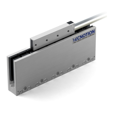
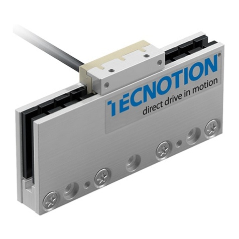
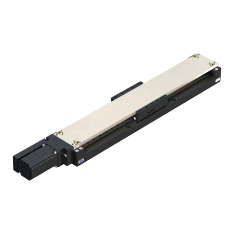
Tecnotion TM3 Series User manual

Iron Core linear motor manual

2
Iron Core linear motor manual - ver. 1.02. Document nr 4022.363.4190.2
©2015 Tecnotion BV - All rights reserved - The contents of this document are subject to change without prior notice.
[ INTRODUCTION ]
A linear motor system is a part of a specific machine. Tecnotion’s Iron core linear motors are components that can be combined
with numerous application devices. This manual is intended for technicians who want to construct a machine that includes a
linear motor system.
It gives insight in the basic components of aTecnotion iron core linear motor and additional components to complete the whole
motion system. The manual further informs about important design and installation aspects of the linear motors. The settings
required before starting up are discussed.
In the appendix the important dimensions for designing the construction that will hold the linear motor can be found. Finally,
the glossary offers insight into the definition of all specifications of a Tecnotion linear motor.
When installing a linear motor system one should be familiar with some important safety remarks. In the first chapter these
remarks are made. Please, read them carefully.

3
Iron Core linear motor manual - ver. 1.02. Document nr 4022.363.4190.2
©2015 Tecnotion BV - All rights reserved - The contents of this document are subject to change without prior notice.
TABLE OF CONTENTS
TOC
TABLE OF CONTENTS
1. [ BEFORE YOU START ] 5
1.1 Important notice 5
1.2 Safety warnings 5
1.3 Certication 7
1.3.1 CE certication
1.3.2 UL / CSA certication
1.3.3 Restriction of Hazardous Substances (RoHS)
2. [ MOTOR COMPONENTS ] 8
2.1 Components 8
2.1.1 Coil unit
2.1.2 Magnet plates
2.1.3 Magnetic eld protection plates
2.1.4 Bolts and dowelpins
2.2 Additional features 10
2.2.1 Analog Hall module
2.2.2 Digital Hall module
2.2.3 Additional motion system components
3. [ MOTOR CONFIGURATION ] 11
3.1 Conguration options 11
3.1.1 Magnet track length
3.1.2 Air gap
3.1.3 Coupling of motors
3.2 Mechanical interface 14
3.2.1 Flatness
3.2.2 Mounting height
3.2.3 Coil positioning over the magnet track
3.2.4 Bolts for coil unit
3.2.5 Dowelpins for coil unit
3.2.6 Magnettrack
3.2.7 Bolts for magnet plates
3.2.8 Dowelpins for magnet plates
3.2.9 Water cooling connections
3.3 Watercooling 18
3.4 Electrical interface 19
3.5 Temperature sensors 21
3.6 Accessories 23
3.6.1 Analog Hall module
3.6.2 Digital Hall module
3.7 Storage 26
4. [ INSTALLATION ] 27
4.1 Installation material 27
4.2 Cleaning 27
4.3 Installation order 28
4.3.1 Mounting the Coil Unit
4.3.2 Mounting the magnet plates
4.4 Electrical connections 33
4.4.1 General remarks
4.4.2 Powerlines
4.4.3 Protective earth
4.4.4 Polarization test
4.4.5 Temperature sensor cable wiring
4.5 De-installation order 34
5. [ ADDITIONAL INSTALLATIONS ] 35
5.1 Stainless steel magnet track cover 35
5.2 Covering the magnet plate 35
5.3 Installing water cooling connections 36
5.3.1 Additional installation material
5.3.2 Fitting water-cooling connections
5.4 Installing the analog hall module 38
5.4.1 Additional installation material
5.4.2 Mounting the analog hall module
5.5 Installing the digital hall module 39
5.5.1 Additional installation material
5.5.2 Mounting the digital hall module

4
Iron Core linear motor manual - ver. 1.02. Document nr 4022.363.4190.2
©2015 Tecnotion BV - All rights reserved - The contents of this document are subject to change without prior notice.
6. [ OPERATION ] 40
6.1 Pre-commissioning 40
6.2 Conguring 40
6.3 Testing 41
6.4 Starting up 41
APPENDIX A 43
Dimensions - TM Coil 43
Dimensions - TM Magnet plates 44
Dimensions - TL Coil 45
Dimensions - TL Magnet plates 46
Dimensions - TB Coil 47
Dimensions - TB Magnet plates 48
Dimensions - TBW Coil 49
Dimensions - TBW Magnet plates 50
APPENDIX B 51
Motor cable conguration 51
APPENDIX C 52
Temperature sensor location 52
APPENDIX D 53
Package weight 53
APPENDIX E 54
EC - ROHS Declaration 54
CSA Certication 55
APPENDIX F 56
Coupling - TM Series 56
Coupling - TL Series 57
APPENDIX F 58
Coupling - TB Series 58
Coupling - TBW Series 59
APPENDIX G 60
F / v Graphs 60
GLOSSARY 66

5
Tecnotion | www.tecnotion.com | [email protected]
Iron Core linear motor manual - ver. 1.02. Document nr 4022.363.4190.2
©2015 Tecnotion BV - All rights reserved - The contents of this document are subject to change without prior notice.
1. [ BEFORE YOU START ]
BEFORE YOU START
CH 1
Please read the following instructions very carefully.
They are important for a safe and warranted installation and operation of
the Linear Motor
1.1 Important notice
Before installing and using the Linear Motor, read this instruction
manual carefully. The manufacturer declines all responsibility
in case of accident or damage due to negligence or lack of
observance of the instructions described in this manual. The
manufacturer also declines all responsibility in case of accident
or damage in conditions that differ from those indicated
in the manual; Tecnotion also declines all responsibility
for damage caused by improper use of the Linear Motor.
Handle the components of the Linear Motor with care, packed
as well as unpacked. Especially the magnet plates are sensitive
to mechanical shocks. Never drop a magnet plate or release it in
an uncontrolled way.
Do not expose the magnets to temperatures higher than 70° C.
The magnets may be demagnetized at higher temperatures.
Unpack the Linear Motor and check its integrity. If there is any
irregularity, contact the dealer or manufacturer, signalling the
nature of the defects.
Make a note of the serial number. This facilitates the
correspondence with the supplier.
1.2 Safety warnings
The Linear Motor is used as a part of a machine. The user has to
take care that the machine as a whole fulfils all CE require-
ments.
The magnet plates show large attraction forces on all soft
magnetic objects such as iron.These forces cannot be controlled
by hand. They may cause serious jamming danger. Do not
bring any soft magnetic objects (iron) nearer than 25cm of the
magnetic side of the magnet plate.
Be sure that the magnetic plates are fixed into your machine
before removing the magnetic field protection plates. Put the
magnetic field protection plates on the magnetic plates again
before dismounting them.
Magnetic sensitive objects like banking cards, pacemakers or
other magnetic information carriers may be damaged if they are
brought within 1m of the magnet plates.
Safety and information symbols:
The lightbulb describes a‘Tip’.
The exclamation mark is a, non safety related, important notice
that the user should be aware of.
The warning signs inform about safety information that the user
should respect.

6
Tecnotion | www.tecnotion.com | [email protected]
Iron Core linear motor manual - ver. 1.02. Document nr 4022.363.4190.2
©2015 Tecnotion BV - All rights reserved - The contents of this document are subject to change without prior notice.
BEFORE YOU START
CH 1
The magnet plate and coil unit can be damaged when cleaned
with a non-prescribed cleaning agent.
Use only Isopropanol as a cleaning agent.
UV Blacklight can cause irreversible damage to the eyes
and other tissue when exposed. When using a UV Blacklight
installation wear appropriate protective clothing and glasses.
The magnet plates attract each other while mounting. This may
cause serious jamming danger. Take care that a magnetplate
does not damage the adjecent magnet plate while mounting.
If at any time and in any situation there is any doubt about
the safety of the Linear Motor, do not use it and contact your
supplier.
The Linear Motor is powered by a servo amplifier. In case of a
power disruption or fatal error this may automatically result in
a free run out of the motor. Make mechanical precautions to
prevent damage on the motor or your machine in the case of
such an event.
Before installing the motor, make sure that the supply mains
are grounded and operate in conformity with the regulations in
force.
Make sure that there is an effective protective earth. Make sure
that there is no voltage at the wire terminals before connecting.
An earth connection does not work on non-conducting
mounting surfaces like granite. In these cases the protective
earth must be established by an earthing wire.
Before carrying out checks or doing any maintenance, clear the
system by disconnecting the voltage. Be sure that there is no
possibility of accidental connections.

7
Iron Core linear motor manual - ver. 1.02. Document nr 4022.363.4190.2
©2015 Tecnotion BV - All rights reserved - The contents of this document are subject to change without prior notice.
BEFORE YOU START
CH 1
Series CE UL / CSA RoHS
TM3 Yes Yes Yes
TM6 Yes Yes Yes
TM12 Yes Yes Yes
TM18 Yes Yes Yes
TL6 Yes Yes Yes
TL9 Yes Yes Yes
TL12 Yes Yes Yes
TL15 Yes Yes Yes
TL18 Yes Yes Yes
TL24 Yes Yes Yes
TB12 Yes Yes Yes
TB15 Yes Yes Yes
TB30 Yes Yes Yes
TBW18 Yes Yes Yes
TBW30 Yes Yes Yes
TBW45 Yes Yes Yes
1.3 Certication
All information about certifications can be found in this chapter. The de-
claration of comformity or compliance can be found in APPENDIX E.
1.3.1 CE certication
Tecnotion B.V. declares that all linear motors mentioned in this Installa-
tion manual are manufactured in accordance with European directive
2006/95/EC and in conformity with the following standards, see table 1.1.
Standard Name of standard
EN 60034-1: 2010 Rotating Electrical Machines,
Part 1: Rating and performance
EN 60204-1: 2010 Safety of machinery - Electrical equipment of machines, Part 1:
General requirements
Table 1.1: Applicable standards
1.3.2 UL / CSA certication
All Tecnotion B.V. Ironcore motors have UL / CSA certification. Please
contact your local Tecnotion representative for more information.
1.3.3 Restriction of Hazardous Substances (RoHS)
Tecnotion B.V. declares to be compliant with the RoHS-guideline. Therefore
Tecnotion ensures that all products are free from lead, cadmium, mercury,
hexavalent chromium, polybrominated biphenyls or polybrominated
diphenyl ethers.
Table 1.2: Overview of applicable standards per motortype

8
Iron Core linear motor manual - ver. 1.02. Document nr 4022.363.4190.2
©2015 Tecnotion BV - All rights reserved - The contents of this document are subject to change without prior notice.
MOTOR COMPONENTS
CH 2
2. [ MOTOR COMPONENTS ]
2.1 Components
Winding TM TL TB TBW
3 6 12 18 6 9 12 15 18 24 12 15 30 18 30 45
Nx x x x x x x x x x x x x
Sx x x x x x x x x x x x x x x x
A Tecnotion iron core linear motor consists out of a coil unit and one or
more magnet plates. Together with a slide, mounting frame, rails and be-
aring system, dampers, encoder, controller and amplifier the linear motor
forms a complete machine concept.
Picture 2.1: A complete axis system with Tecnotion coil unit and magnet plates installed
2.1.1 Coil unit
Tecnotion offers most of the coilunits as an N- and S-winding version. What
type is required depends on the voltage, current and speed requirements
of the application.
The N-winding type is optimized for current, enabling the use of a smaller
less costly amplifier. S-winding is optimized for higher speeds or lower
voltages. It can however require a larger amplifier.
Table2.3: available N- and S-winding type coilunits
Tecnotion only supplies coils and magnet plates and offers a few additional
components like Hall modules and stainless steel cover plates. All other
components need to be sourced from other suppliers. Please review this
chapter carefully to determine what is necessary to design a complete
system.
Picture2.2: A TL6 coil unit
Power cable
Temperature
sensor cable
Coil unit
Bearing
Damper
Ruler
Slide
Cable chain
Magnet plate
Rail
Encoder

9
Iron Core linear motor manual - ver. 1.02. Document nr 4022.363.4190.2
©2015 Tecnotion BV - All rights reserved - The contents of this document are subject to change without prior notice.
MOTOR COMPONENTS
CH 2
All iron core linear motors have various magnet plate lengths. This enables
efficient design of the magnet track length. For more information on
magnet track design please review chapter 3.1.1 Magnet track length on
page 11
To prevent serious jamming danger only handle the magnet
plates covered with the magnetic field protection plates.
2.1.2 Magnet plates
Picture 2.4: A TL192mm magnet plate
2.1.3 Magnetic eld protection plates
Magnet plates produce very high attraction forces. These forces are
unpredictable and cannot be controlled by hand.
Tecnotion iron core magnet plates are always delivered with protective
plates. These plates function as a shield for the magnetic forces. With the
protective plates the magnet plates can be handled safely.
Also use the protective plates during assembly and disassembly. Please
review chapter 4.3.2 Mounting the magnet plates on page 30 how to
do this.
Picture 2.5: A magnet plate with a protection plate.

10
Iron Core linear motor manual - ver. 1.02. Document nr 4022.363.4190.2
©2015 Tecnotion BV - All rights reserved - The contents of this document are subject to change without prior notice.
MOTOR COMPONENTS
CH 2
Picture 2.6: The analog hall module
Picture 2.7: The digital hall module
Applying too long bolts for the coil unit may inconspicuously
cause damage and dangerous situations. Please, check
(1) bolt length before mounting
(2) bolt height after mounting
2.1.4 Bolts and dowelpins
The bolts and dowelpins for mounting the coil and magnet plates are
not provided by Tecnotion. The bolt length depends on the mechanical
dimensions of the mounting slide.
Please review chapter 4.3.1 Mounting the Coil Unit on page 29 and
4.3.2 Mounting the magnet plates on page 30 to see what bolts and
dowelpins are required.
2.2 Additional features
The components mentioned in this paragraph can also be delivered by
Tecnotion. The digital hall module for commutation and the analog hall
module for positioning can be used as cost effective alternatives to a
separate encoder system when positioning requirements are not extreme.
The maximal repeatable accuracy is ~30 µm and absolute accuracy is
~ 100 µm, depending on the interpolation. Finally Tecnotion can also
deliver a stainless steel cover plate for the magnet track.
2.2.1 Analog Hall module
This analog hall module can function as a incremental encoder. It uses the
magnettrack as the linear scale. Please review chapter 5.4 Installing the
analog hall module on page 38 for more information.
2.2.2 Digital Hall module
The digital hall module can be used when a controller does not offer the
possibility to commutate within the servo drive. It uses the magnettrack as
the linear scale. Please review chapter 5.5 Installing the digital hall module
on page 39 for more information.

11
Iron Core linear motor manual - ver. 1.02. Document nr 4022.363.4190.2
©2015 Tecnotion BV - All rights reserved - The contents of this document are subject to change without prior notice.
MOTOR COMPONENTS
CH 3
2.2.3 Additional motion system components
A complete motion system would require at a minimum the following
components that are not supplied by Tecnotion.
■Power supply
■Cables and connectors
■Amplifier and servo controller system
■Bearing system
■Ruler and encoder system if Tecnotion’s analog or digital hall module
is not used
■Bolts and dowelpins
3. [ MOTOR CONFIGURATION ]
3.1 Conguration options
Individual iron core coils can be coupled.This can be done on two separate
magnet tracks for gantry type applications or on a single magnet track to
yield more force.
This last option is especially interesting for cost reduction in long stroke
applications.
By coupling two coils a smaller series coil and magnet track can be used.
This will reduce the magnet track cost.
3.1.1 Magnet track length
This paragraph describes how to determine the required amount of mag-
net plates for an application. There are two ways to determine the required
amount.
The easiest way to determine the required number of magnet plates is to
add up the necessary stroke for the application and the length of the coil
unit. Please review the example for further information. This will provide
the minimum magnet track length that needs to be constructed with the
available magnet plate sizes. Please refer to APPENDIX A for an overview of
the available length per series.

12
Iron Core linear motor manual - ver. 1.02. Document nr 4022.363.4190.2
©2015 Tecnotion BV - All rights reserved - The contents of this document are subject to change without prior notice.
It can be cost effective to determine the required magnet track length by
means of the effective area instead of the coil unit length. This is especially
interesting when an extra magnet plate is required to attain the minimum
hub length when, according to the coil length, it falls short by approxima-
tely 25mm. This method will save the need for one magnet plate.
The effective area of a coil unit is the area where the actual windings are
situated in the coil, see picture 3.1. In this area the force is created that
propels a linear motor. The remaining space accommodates for example
the wiring, the PCB or filler material. This non effective area of the coil can
overrun the end of the magnet track without any loss of force.
ABC
Picture 3.1: Location of effective area
Example
Magnet length calculation with coil
unit length
Hr = Required stroke 440mm
Lc = TL6 Coil unit length 146mm
Mpl = Magnet plate length 288mm
Required number of magnet plates
=(Hr+Lc)/Mpl>two288mmmagnetplates
Magnet length calculation by means
of effective area
Hr = Required stroke 440mm
Leff = Lc – (a + b) = TL6 Coil unit effective
area 114mm
Mpl = Magnet plate length 288mm
Required number of magnet plates
=(Hr+Leff)/Mpl<two288mm magnetplates
Table 3.2 states the location where the effective area of a coil starts and
ends.
TM
Parameter Unit Dimension 3 6 12 18
Cableside mm A19 23 23 26,7
End mm B 8 6 2 3,7
Effective area mm C66 114 216 305,6
TL
Parameter Unit Dimension 6 9 12 15 18 24
Cableside mm A26 25 26 26,2 26,7 26
End mm B 6 5 2 6,2 3,7 2
Effective area mm C114 164 216 257,6 305,6 440
TB TBW
Parameter Unit Dimension 12 15 30 18 30 45
Cableside mm A26 26,2 26,2 34,7 39,2 39,2
End mm B 2 6,2 6,2 3,7 11,2 11,2
Effective area mm C216 257,6 529,6 305,6 529,6 801,6
Table 3.2: Dimensions of the effective area per motor type
3.1.2 Air gap
The air gap between the magnet plates and the coil unit can be increased
to overcome tolerance issues in clearance or deviations in parallelism or
flatness. Especially for large axis configurations this can be helpful.
Decreasing the air gap is not recommended because of the tight toleran-
ces this creates for the mechanics in the design and the increase in costs
this creates.
CH 3

13
Iron Core linear motor manual - ver. 1.02. Document nr 4022.363.4190.2
©2015 Tecnotion BV - All rights reserved - The contents of this document are subject to change without prior notice.
MOTOR CONFIGURATION
CH 3
Mounting height (nominal)
TM,TL series 40mm ±0.1mm
TB series 45mm ±0.1mm
TBW series 47mm ±0.1mm
Table 3.3: Mounting height of T-Series
Tecnotion doesn’t specify the nominal air gap because of the casted finish
of the coil unit and the magnet plate. This finish makes it difficult to get
an accurate reading of the air gap with the use of a feeler gage. To get an
accurate measurement Tecnotion advices to derive the air gap from the
total mounting height .
The reduction in force which the increase of the air gap creates is a non-li-
near function which is showed in graph 3.3.
0%
20%
40%
60%
80%
100%
0 2 4 6 8
Percentage of nominal Fc (%)
Airgap (mm)
Fc
Fa
Graph 3.3 Continuous force and attraction force airgap dependency.
3.1.3 Coupling of motors
Different type of motors within one series can be coupled as long as they
have the same motor constant (N and S can not be coupled). The forces of
both coils can be added up.
Motors must always be connected to the drive in parallel. Series coupling
isn’t possible because of voltage limitations of the cables. Refer to appen-
dix F for details about phase connections.
Parallel coupled: If cables of both motors face the same direction then
the motors can simply be placed at the same position on each individual
magnet plate parallel to each other.
In line coupling: Different orientations are possible.
.
.
.
.
.
.
Cables facing each other
Cables facing left or right
Cables facing outwards

14
Iron Core linear motor manual - ver. 1.02. Document nr 4022.363.4190.2
©2015 Tecnotion BV - All rights reserved - The contents of this document are subject to change without prior notice.
MOTOR CONFIGURATION
CH 3
Applying too long bolts for the coil unit may inconspicuously
cause damage and dangerous situations. Please, check
(1) bolt length before mounting
(2) bolt height after mounting
Use only the specified type of flat head fasteners with the correct
length. The coil and magnet plate can be damaged by non flat
head bolts.
Make sure the dowelpins do not extend further than the
specified height. The magnet plate can be damaged by too long
dowelpins.
The use of other water cooling connnections may cause higher
pressure drops than indicated due to smaller throughput.
3.2 Mechanical interface
When using a Tecnotion linear motor please take notice of the ad-
vice, tips and warnings in this chapter. It will make sure that your li-
near motor will perform as best as possible. Special attention should
be given to the orientation of the coil over the magnet track. All
dimensions for the ironcore series products can be found in APPENDIX A.
3.2.1 Flatness
With the prescribed flatness, see picture 3.4, the specified mounting height
can be used. If a lower flatness ratio is to be used the mounting height
needs to be increased. Please refer to 3.2.2 Mounting height on page 15
for further information.
Details about minimum mounting distances between both coils can be
found in appendix F. For other coupling possibilities please contact your
local Tecnotion representative.
Use only one of the temperature sensors
Make sure that the cables of both motors have exactly the same length
Please remember to respect the coil positioning over the magnet track as
described in 3.2.3
Picture 3.4: Flatness and parallelism requirements for coil and magnet plate
r
0,1
i
0,1 A
r
0,1
Mounting Frame
Magnet Plate
Coil Unit
Slide
H
u
0,1mm
A

15
Iron Core linear motor manual - ver. 1.02. Document nr 4022.363.4190.2
©2015 Tecnotion BV - All rights reserved - The contents of this document are subject to change without prior notice.
MOTOR CONFIGURATION
CH 3
Picture 3.5: Non symmetrical positioning of the coil unit over the magnet track
Applying too long bolts for the coil unit may inconspicuously
cause damage and dangerous situations. Please, check
(1) bolt length before mounting
(2) bolt height after mounting
All mounting holes must be used. The bolt length depends on the
mechanical dimensions of the mounting slide, see table 3.6.
3.2.2 Mounting height
By using the specified mounting height between the bottom of the magnet
plate and the top of the coil unit the correct air gap will be attained.The air
gap between the coil and magnet plate does not need to be verified. Refer
to APPENDIX A for the dimensions.
The mounting height can be increased. This will cause the rated
specifications of the linear motor to deteriorate exponentially.
For more information on air gap influences refer to 3.1.3 Coupling of motors
on page 13.
3.2.3 Coil positioning over the magnet track
Do not construct the coils symmetrically over the magnet track. The
windings are not positioned in the middle of the coil.This would deteriorate
the available force. Please construct according to the specified dimension
in drawing 0 in APPENDIX A in this manual.
The dowel pin holes of the coil unit will exactly line up over the length axis
of the magnet plate when properly constructed, see picture 3.5.
Dowel pin
Magnetplate magnec
and mechanical cen-
terline
3.2.4 Bolts for coil unit
Bolts for coil unit TM TL TB and TBW
Bolts (steel) M4
DIN912
M5
DIN912
M5
DIN912
Depth bolt in thread hole Min: 4 mm
Max: 5 mm
Min 4 mm
Max: 5 mm
Min: 4.5 mm
Max: 6 mm
Tightening torque 2.0 – 3.0 Nm 3.0 – 5.0 Nm
Dowelpins (stainless) 5h8 M3
Table 3.6: Bolts for coil unit

16
Iron Core linear motor manual - ver. 1.02. Document nr 4022.363.4190.2
©2015 Tecnotion BV - All rights reserved - The contents of this document are subject to change without prior notice.
Positioning holes
Mounting holes
Positioning holes
for Dowelpins
Mounting holes with
inner M5 thread
MOTOR CONFIGURATION
CH 3
Dowelpins for coil unit TM TL TB/TBW
Dowelpins (Stainless) 5h8 M3
Table 3.7: Dowelpins for coil unit
3.2.5 Dowelpins for coil unit
Use only the specified type of flat head fasteners with the correct
length. The coil and magnet plate can be damaged by non flat
head bolts.
Make sure the dowelpins do not extend further than the
specified height. The magnet plate can be damaged by too long
dowelpins.
3.2.6 Magnettrack
For short magnet track length magnet plates can be butted directly
together. For magnet track length over 2000mm or when using the analog
hall module it is advised to use positioning holes with dowelpins.
Picture 3.8: Location of the mounting holes, dowel pin and reference marker
The magnet plates have a magnetic north and south pole. They need to be
correctly positioned adjacent to each other. This can be verified in several
ways:
■The dowel pin holes should be on the same side
■The reference marker between the mounting holes on one side of the
magnet plate should all be on the same side
■Adjacent magnet plates should attract and not repel each other
Bolts for magnet plates TM TL TB/TBW
Bolts (steel) M5x10, DIN7984 M5x10, DIN7984 M5x16, DIN912
Depth bolt in thread hole Min: 6.5mm
Tightening torque 2.0 –3.5Nm
Reference marker
Table 3.9: Flathead bolts for magnet plates
3.2.7 Bolts for magnet plates
Dowelpins for magnet plates TM TL TB/TBW
Dowelpins (stainless) 5h8 M3
Table 3.10: Dowelpins for magnet plates
3.2.8 Dowelpins for magnet plates
3.2.9 Water cooling connections
The TL and TBW series come equipped with integrated water cooling
channels. These can be used when water cooling is required to attain a
higher continuous force.
Dowel pin holes

17
Iron Core linear motor manual - ver. 1.02. Document nr 4022.363.4190.2
©2015 Tecnotion BV - All rights reserved - The contents of this document are subject to change without prior notice.
MOTOR CONFIGURATION
CH 3
The use of other connnections may cause higher pressure drops
than indicated due to smaller throughput.
Picture 3.13: TBW water cooling channels form a closed loop within the coil unit. The entrance and
exit holes of the cooling channels are located on the same side of the coil unit.
For the TL series the nipples will extend above the top mounting surface
of the coil, see picture 3.12. The slide needs to accommodate room for this.
Hose
Nipple Coil unit - TL
Slide
Beware of extending
nippels
Picture 3.12: TL nipples extend above mounting surface
TBW water cooling
The watercooling channels for the TBW series form a closed loop within the
coil unit, see picture 3.13. The entrance and exit are located on one side of
the coil unit. Please refer to Table 3.14: recommendations for TL and TBW
water cooling connections. on page 18 for the nipples dimensions.
Picture 3.11: TL water cooling channels run completely through the coil. The cooling circuit needs
to be closed externally by means of a tube.
TL water cooling
The TL series coils come equipped with two channels that run completely
throughthecoilunit,seepicture 3.13.Thecircuitneedstobeclosed externally
by means of a tube. Please refer to Table 3.14: recommendations for TL and
TBW water cooling connections. on page 18 for the nipple dimensions.

18
Iron Core linear motor manual - ver. 1.02. Document nr 4022.363.4190.2
©2015 Tecnotion BV - All rights reserved - The contents of this document are subject to change without prior notice.
MOTOR CONFIGURATION
CH 3
3.3 Watercooling
Tecnotion TL and TBW series iron core motors come equipped with wa-
ter cooling capabilities. The continuous force water cooled specifications
for the TL and TBW series are based on pure water cooling. This chapter
explains how to design your water cooling system with water and other
common coolants.
Further information regarding the location and dimension of the
water cooling connections can be found in chapter 3.2.9 Water cooling
connections on page 16.
Connection of hoses
When fitting the hoses, the connections have to be free of greases and oil.
The two cooling channels of the TL-motor can be connected in series. Both
cooling channels can also be used in parallel configuration. This connecti-
on reduces the pressure drop, but only if cavitation is less ø6mm-ø8mm,
when using Y-joints.
TL-series TBW-series
Hose diameter ø4mm (inner diameter) Ø8mm (outer diameter)
Minimum flow diameter fitting ø2.5mm Ø5mm
Hose examples: Festo PU-4*
Rauclair PVC E 4x1*
flexible
Festo PUN-H-8x1,25*
*Other hoses can also be applied, but the outer diameter should Ø8mm to fit properly on a 1/8”
push and pull fitting.
Table 3.15: Recommended watercooling connections
TL6 TL12 TL15 TL18 TL24 TBW18 TBW30 TBW45
Minimum
Flow (l/min)*
0.7 1.4 1.8 2.2 2.9 3.1 5.2 7.8
Pressure drop
(bar)*
1 2 2 2 3 1 1.5 2.5
*Values are based on pure water coolant and depend on used connections and hose-system.
Table 3.16: Presure drop value per coil type
Nipples TL-series TBW-series
Thread holes 4 times M5 (on both
sides of coilunit)
2 times 1/8”NPT (both on
one side)
Recommended Nipple/Fitting M5 nipple Push-Pull Fitting, -Festo
QS-1/8-8*
Sealings M5 plastic sealings and
Loctite 638/648 glue
Teflon tape
Tightening torque 0,2 - 0,3 Nm 4.0 Nm
* Other 1/8” Push and Pull Fitting can also be applied. The use of smaller hose diameter and /or
nipple diameter can reduce the flow.
Table 3.14: recommendations for TL and TBW water cooling connections.

19
Iron Core linear motor manual - ver. 1.02. Document nr 4022.363.4190.2
©2015 Tecnotion BV - All rights reserved - The contents of this document are subject to change without prior notice.
MOTOR CONFIGURATION
CH 3
3.4 Electrical interface
Be sure your machine as a whole meets the requirements of all
applicable electrical standards, such as the EN 60204 standard.
Cables
Tecnotion linear motor’s electrical wiring is externally configured with two
cables:
■a power cable
■a temperature sensor cable.
Both power cable and temperature sensor cable are shielded with a brai-
ded metal cable shield.
Details about the motor cable configuration can be found in appendix B
on page 52.
The TM series comes equipped with a 3m long power- and temperature
sensor cable suited for use in a power chain. All other motors have a 1m
long non flexible cable.
Cable Type
Series
Length Remark TM TL TB TBW
Power 1m X X X
3m Flex X
Temperature 1m X X X
3m Flex X
For wiring scheme of both cables please see the figure 3.18. If desired you
can shorten these cables and provide them with appropriate connectors.
Servo
amplifier
L1
L3 L2
PTC
KTY
L1
L2
L3
PE
green/
yellow
white
brown
yellow
green
Linear motor
Slide
Power cable
Temperature
sensor cable
Figure 3.18: Wiring scheme for iron core
Not all cables are meant for use within cable chains. Therefore user defin-
ed cables should be used that meet the specifications concerning bending
radius, length, replacebility, velocity, acceleration, etc. The coil’s standard
cables must be connected properly to the user defined cables.
Table 3.17: Cable length per series

20
Iron Core linear motor manual - ver. 1.02. Document nr 4022.363.4190.2
©2015 Tecnotion BV - All rights reserved - The contents of this document are subject to change without prior notice.
MOTOR CONFIGURATION
CH 3
Power cable
The power cable can be confectioned by the user to fit the servo drive. All
motors require an extra flexible cable between the coil and the servo drive
except for the TM –series.
Powercable Color code TM/TL/TB/TBW Connection to servo controller
3-phases L1 black‘1’ 3-phases
L2 black‘2’
L3 black‘3’
Protective Earth green/yellow Protective Earth
Shield Metal shield Protective Earth
Table 3.19: Power cables wire identification
Protective earth
Internally the motor’s protective earth wire is galvanically connected to the
motor housing. This wire must be connected to the protective earth con-
nector of the servo amplifier.
Provide the motor system with protective earth lines to the amplifier that
are as short as possible.
Provide the magnet track with an effective protective earth connection.
Temperature sensor cable
The coil unit is equipped with two temperature sensors, one PTC-1k-type
for protection and one of the KTY83-122 type for temperature measure-
ment.
Please refer to chapter 3.5 Temperature sensors on page 21 for more
information regarding the sensors. The temperature cable consists of four
wires. For wire color and function, see table 3.19. Refer to Table 3.17: Cable
length per series on page 19 for the length of the temperature sensor
cable.
All motors require an extra flexible temperature sensor cable between the
coil and the servo drive except for the TM-series.
Sensor cable (color) Connection to servo controller
PTC (white) PTC
PTC (brown) PTC
KTY83-122 (green ) KTY83-122
KTY83-122 (yellow) KTY83-122
Shield Protective Earth
Table 3.20: Sensor cable wire identification
This manual suits for next models
15
Table of contents
Other Tecnotion Engine manuals
Popular Engine manuals by other brands

MPI
MPI Himax HC2816 Series manual
Assun
Assun AM-CL1935MAE Series product manual

Robin America
Robin America EH12-2, EH17-2, EH25-2 parts manual
Weston UK
Weston UK WEST EUROTECH 52 V2 instructions

Nice
Nice Era Fit S Instructions and warnings for installation and use

Ingersoll-Rand
Ingersoll-Rand AF0860 Series Operator's manual
