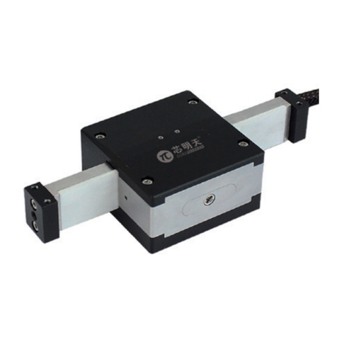
Tecnotion UC3 Series User manual

Ironless linear motor manual

2
Ironless linear motor manual - ver. 1.03
©2016 Tecnotion BV - All rights reserved - The contents of this document are subject to change without prior notice.
[ INTRODUCTION ]
A linear motor system is a part of a specific machine. Tecnotion’s Ironless linear motors are components that can be combined
with numerous application devices. This manual is intended for technicians who want to construct a machine that includes a
linear motor system.
It gives insight in the basic components of a Tecnotion ironless linear motor and additional components to complete the whole
motion system. The manual further informs about important design and installation aspects of the linear motors. The settings
required before starting up are discussed.
In the appendix the important dimensions for designing the construction that will hold the linear motor can be found. Finally,
the glossary gives insight in the definition of all specifications of a Tecnotion linear motor.
When installing a linear motor system one should be familiar with some important safety remarks. In the first chapter these
remarks are made. Please, read them carefully.

©2016 Tecnotion BV - All rights reserved - The contents of this document are subject to change without prior notice.
3
Tecnotion | www.tecnotion.com | [email protected]
Ironless linear motor manual - ver. 1.03
TABLE OF CONTENTS
TOC
TABLE OF CONTENTS
1. [ BEFORE YOU START ] 4
1.2 Safety warnings 4
1.3 Certication 6
1.3.1 CE certication
1.3.2 UL / CSA certication
1.3.3 Restriction of Hazardous Substance (RoHS)
2. [ MOTOR COMPONENTS ] 7
2.1 Basic components 7
2.2 Additional features 8
2.2.1 Bolts and dowel pins
2.2.2 Controller and measurement unit
2.2.3 Tools
3. [ INSTALLATION ] 9
3.1 Cleaning 9
3.2 Cleanroom cleaning 9
3.2.1 Tools
3.2.2 Cleaning instructions
3.3 Installation 11
3.4 Requirements for the mounting surface 12
3.5 Magnet yoke mounting 13
3.6 Coil unit mounting instructions 14
3.7 Electrical connections 14
3.7.1 General remarks
3.7.2 Power lines
3.7.3 Protective earth
3.7.4 Temperature Sensor
3.7.5 Temperature protection
3.7.6 PTC specication
3.7.7 Maximum operating temperature
3.7.8 NTC Characteristic
3.7.9 Polarization test
3.8 Transportation 19
3.9 Storage 19
4. [ OPERATION ] 20
4.1 Pre-commissioning 20
4.2 Conguring 20
4.3 Testing 21
4.3.1 End switches
4.4 Starting up 21
[ APPENDIX ]
APPENDIX A Dimensions - UC 22
APPENDIX B Motor cable conguration 28
APPENDIX C Digital Hall Modules 30
APPENDIX D Vacuum Installation 35
APPENDIX E Declarations 37
APPENDIX F F / v Graphs 38
GLOSSARY 43

4
Tecnotion | www.tecnotion.com | [email protected]
Ironless linear motor manual - ver. 1.03
©2016 Tecnotion BV - All rights reserved - The contents of this document are subject to change without prior notice.
BEFORE YOU START
CH 1
1. [ BEFORE YOU START ]
Please read the following instructions very carefully.
They are important for a safe and warranted installation and operation of
the Linear Motor.
1.1. Important notice
Before installing and using the Linear Motor, read this instruction
manual carefully. The manufacturer declines all responsibility
in case of accident or damage due to negligence or lack of
observance of the instructions described in this manual. The
manufacturer also declines all responsibility in case of accident
or damage in conditions that differ from those indicated in the
manual; Tecnotion also declines all responsibility for damage
caused by improper use of the Linear Motor.
Handle the components of the Linear Motor with care, packed
as well as unpacked. Especially the magnet yokes are sensitive
to mechanical shocks. Never drop a magnet yoke or release it in
an uncontrolled way.
Do not expose the magnets to temperatures higher than 70° C.
The magnets may be demagnetized at higher temperatures.
Unpack the Linear Motor and check its integrity. If there is any
irregularity. If there is any irregularity contact the dealer or
manufacturer, signalling the nature of the defects.
Make a note of the serial number. This facilitates the
correspondence with the supplier.
Safety and information symbols:
The lightbulb describes a‘Tip’.
The exclamation mark is a, non safety related, important notice
that the user should be aware of.
The warning signs inform about safety information that the user
should respect.
1.2 Safety warnings
The Linear Motor is used as a part of a machine. The machine
manufacturer or representative has to take care that the
machine as a whole fulfils all CE requirements.
The magnet yokes show large attraction forces on all soft
magnetic objects such as iron.These forces cannot be controlled
by hand. They may cause serious jamming danger. Do not
bring any soft magnetic objects (iron) nearer than 25cm of the
magnetic side of the magnet yoke.
Magnetic sensitive objects like banking cards, pacemakers or
other magnetic information carriers may be damaged if they are
brought within 1m of the magnet yokes.

5
Tecnotion | www.tecnotion.com | [email protected]
Ironless linear motor manual - ver. 1.03
©2016 Tecnotion BV - All rights reserved - The contents of this document are subject to change without prior notice.
BEFORE YOU START
CH 1
The magnet yoke and coil unit can be damaged when cleaned
with a non-prescribed cleaning agent.
Use only isopropanol as a cleaning agent.
UV Blacklight can cause irreversible damage to the eyes
and other tissue when exposed. When using a UV Blacklight
installation wear appropriate protective clothing and glasses.
The magnet yokes do attract each other while mounting. Take
care that the closing plates of one yoke do not damage the
magnets of the neighbour magnet yoke while mounting.
If at any time and in any situation there is any doubt about
the safety of the Linear Motor, do not use it and contact your
supplier.
The Linear Motor is powered by a servo amplifier. In case of a
power disruption or fatal error this may automatically result in
a free run out of the motor. Make mechanical precautions to
prevent damage on the motor or your machine in the case of
such an event.
Before installing the motor, make sure that the supply mains
are grounded and operate in conformity with the regulations in
force.
Make sure that there is an effective protective earth.
Make sure that there is no voltage at the wire terminals before
connecting.
An earth connection does not work on non-conducting
mounting surfaces like granite. In these cases the protective
earth must be established by an earthing wire
Before carrying out checks or doing any maintenance, clear the
system by disconnecting the voltage. Be sure that there is no
possibility of accidental connections.

©2016 Tecnotion BV - All rights reserved - The contents of this document are subject to change without prior notice.
6
Tecnotion | www.tecnotion.com | [email protected]
Ironless linear motor manual - ver. 1.03
BEFORE YOU START
CH 1
Series CE UL / CSA RoHS
UC3 Yes No Yes
UC6 Yes No Yes
UF3 Yes No Yes
UF6 Yes No Yes
UM3 Yes No Yes
UM6 Yes No Yes
UM9 Yes No Yes
UM12 Yes No Yes
UMV12 Yes No Yes
UL3 Yes No Yes
UL6 Yes No Yes
UL9 Yes No Yes
ULV9 Yes No Yes
UL12 Yes No Yes
UL15 Yes No Yes
UXA3 Yes No Yes
UXA6 Yes No Yes
UXA9 Yes No Yes
UXA12 Yes No Yes
UXA18 Yes No Yes
UXX3 Yes No Yes
UXX6 Yes No Yes
UXX9 Yes No Yes
UXX12 Yes No Yes
UXX18 Yes No Yes
Table 1.2: Overview of applicable standards per motortype
1.3 Certication
All information about certifications can be found in this chapter. The
declaration of comformity can be found in APPENDIX E.
1.3.1 CE certication
Tecnotion B.V. declares that the UM, UL, UX,UXA and UXX linear motors
mentioned in this Installation manual are manufactured in accordance
with European directive 2006/95/EC and in conformity with the following
standards, see table 1.1.
Tecnotion B.V. declares that the UC and UF linear motors mentioned in
this Installation manual are destined to be incorporated in other machines
or to be combined with other machines, and is not (entirely) in complian-
ce with the Machine Directive (98/37/EC). The UC and UF linear motors are
in conformity with the following standards, see table 1.1.
1.3.2 UL / CSA certication
Tecnotion B.V. Ironless motors currently do not have UL / CSA certification.
Please contact your local Tecnotion representative for more information.
Standard Name of standard
EN 60034-1: 2010 Rotating Electrical Machines,
Part 1: Rating and performance
EN 60204-1: 2010 Safety of machinery - Electrical equipment of machines, Part 1:
General requirements
Table 1.1: Applicable standards
1.3.3 Restriction of Hazardous Substance (RoHS)
Tecnotion B.V. declares to be compliant with the RoHS-guideline. Therefore
Tecnotion ensures that all products are free from lead, cadmium, mercury,
hexavalent chromium, polybrominated biphenyls or probrominated
diphenyl ethers.

©2016 Tecnotion BV - All rights reserved - The contents of this document are subject to change without prior notice.
7
Tecnotion | www.tecnotion.com | [email protected]
Ironless linear motor manual - ver. 1.03
MOTOR COMPONENTS
CH 2
2. [ MOTOR COMPONENTS ]
An ironless linear motor of Tecnotion is not a system on itself. It contains
several components, such as a coil unit and magnet yokes. The compo-
nents should be build within a total machine concept or a working unit.
The size and the shape of the mounting frame, the design of the slide, the
type bearings or the kind of dampers depend of the required application.
For instance the mounting frame and the slide should be designed in such
a way that a correct air gap between coil unit and magnet yokes will be
obtained.
Tecnotion provides standard and special components which are suitable
for numerous linear motor applications. These components can easily be
applied in your system.
2.1 Basic components
The basic Linear Motor components supplied by Tecnotion are:
■The coil unit (the N and S version differing in voltage and current re-
quirements)
■The magnet yoke (in different lengths, varying in outer dimensions)
Picture 2.1: A complete ironless linear motor system
Picture 2.2: A coil unit and magnet yoke

©2016 Tecnotion BV - All rights reserved - The contents of this document are subject to change without prior notice.
8
Tecnotion | www.tecnotion.com | [email protected]
Ironless linear motor manual - ver. 1.03
MOTOR COMPONENTS
CH 2
2.2 Additional features
For a proper installation of your linear motor system you also need:
■fixing components, like bolts and dowel pins;
■additional devices, like a servo controller and a linear encoder;
■the right tools.
These features are no part of Tecnotion’s standard delivery.
2.2.1 Bolts and dowel pins
The following bolts and dowel pins are required for positioning and fixing
the coil unit to the slide as well as connecting the magnet yokes to the
mounting frame:
Features UM UL UXA UXX
Bolts for coil unit (steel) M3x16,
DIN912
M4x20,
DIN912
M5x20,
DIN912
M5x20,
DIN912
Tightening torque 1.0 - 2.0 Nm 2.0 - 3.0 Nm 3.0 - 5.0 Nm 3.0 - 5.0 Nm
Bolts for magnet yoke
(steel)
M4x25,
DIN912
M5x35,
DIN912
M6x40,
DIN912
M6x50,
DIN912
Dowel pins for magnet
yoke (optional) 3h8, DIN7
Table 2.4: Bolts for coil unit and yoke UC and UF series
Features UC UF
Bolts for coil unit (steel) M3, DIN912, Class 12.9 M3, DIN912, Class 12.9
Tightening torque 1.0 - 2.0 Nm 1.0 - 2.0 Nm
Dept bolt in threat hole Top: through coil unit
Side: 1.5 - 2.8mm
Top: through coil unit
Side: 1.5 - 2.8mm
Bolts for magnet yoke (steel) M4x20, DIN912 M4x25, DIN912
Dowel pins for magnet yoke
(optional) 3h8, DIN7
Table 2.3: Bolts for coil unit and yoke UM,UL,UXA and UXX series
2.2.2 Controller and measurement unit
Required is:
■An appropriate servo controller/amplifier
■A ruler and a linear encoder or an Hall module
■Power supply, cabling and connectors
For more information please contact Tecnotion.
2.2.3 Tools
Necessary for the installation is:
■Allen Key set
Occasionally useful are:
■Heat sink compound (optional)
■Isopropanolwipes to clean mounting surfaces

©2016 Tecnotion BV - All rights reserved - The contents of this document are subject to change without prior notice.
9
Tecnotion | www.tecnotion.com | [email protected]
Ironless linear motor manual - ver. 1.03
INSTALLATION
CH 3
3. [ INSTALLATION ]
3.1 Cleaning
The magnet yokes show large attraction forces on all soft
magnetic objects such as iron. These forces cannot be controlled
by hand. They may cause serious jamming danger.
Do not bring any soft magnetic objects (iron) nearer than 1m of
the magnetic side of the magnet yoke.
Magnetic sensitive objects like banking cards, pacemakers or
other magnetic information carriers may be damaged if they are
brought within 25cm of the magnet yokes.
The magnet yoke and coil unit can be damaged when cleaned
with a non-prescribed cleaning agent.
Use only Isopropanol as a cleaning agent.
For general, non-cleanroom applications, the magnet yokes and coil units
do not need to be cleaned intensively.
For cleaning purposes Tecnotions prescribes Isopropanol as cleaning agent
for the magnet yoke and coil.
3.2 Cleanroom cleaning
For cleanroom applications Tecnotion products need to be cleaned additi-
onally to remove dust particles.
3.2.1 Tools
■Isopropanol cleaning wipes
■Filtered pressed air installation
■Blacklight installation
■UV Glasses
■Cleanroom compatible vacuum cleaner
■Cotton swap

©2016 Tecnotion BV - All rights reserved - The contents of this document are subject to change without prior notice.
10
Tecnotion | www.tecnotion.com | [email protected]
Ironless linear motor manual - ver. 1.03
INSTALLATION
CH 3
3.2.2 Cleaning instructions
Only the cleaning of the yokes is described. The same method can be used
to clean the coils and the cables.
Initial cleaning
1. Clean the workstation with Isopropanol cleaning wipes (IPA).
Make sure the workstation is clean.
2. Blow filtered pressed air in to the gap between each pair of
magnets.
3. Blow filtered pressed air in to the side of the yoke. Repeat for
the other side.
7. Clean the yoke with a cleanroom compatible vacuum cleaner.
8. Repeat the process for the other side of the yoke.
9. Clean all sides of the magnet yoke with IPA cleaning wipes.
Only move the IPA cleaning wipe in one direction, do not move back and
forward. This will enhance the cleaning action.
10. Clean the inside of the magnet yoke with an IPA cleaning wipe
and a cotton swab.
Verication of cleaning
11. Inspect the magnet yoke with the blacklight installation for
remaining dust particles.
Especially check the areas between the magnets and the gab between the
magnets and the bottom of the yoke.
12. Ifdustparticlesarevisible:RemovethemwithanIPAcleaning wipe
andcottonswabuntilthesurface is cleaned toanacceptablelevel.
UV Blacklight can cause irreversible damage to the eyes and other
tissue when exposed. When using a UV Blacklight installation
wear appropriate protective clothing and glasses.
Verication of surface pollution
4. Inspect the yoke with the blacklight installation for dust particles.
Intensive cleaning
5. Clean the workstation with IPA cleaning wipes.
6. Place the magnet yoke on the cleaned workstation.
step 1/5 step 2 step 3 step 4/11 step 7/8 step 9

©2016 Tecnotion BV - All rights reserved - The contents of this document are subject to change without prior notice.
11
Tecnotion | www.tecnotion.com | [email protected]
Ironless linear motor manual - ver. 1.03
INSTALLATION
CH 3
Picture 3.1: A ironless linear motor system
Picture 3.2: Coil unit, slide, magnet yoke and mounting surface
3.3 Installation
Vacuum installation
For installation of vacuum motors special instructions are required, these
instructions can be found in the vacuum appendix.
Before installing the Linear Motor components, the installation of the
mounting frame should be completed. The slide should be provided with
bearings, dampers, linear probe and required cabling in such a way that
a smooth, save and well positioned transport of the slide over the stroke
is established. The ruler should be properly positioned and fixed to the
frame. The operation of bearings and dampers should be tested as well as
the guidance of the moving cables.
The correct installation order is for electrical safety reasons:
1. Mount the magnet yokes to the mounting surface of the machine.
2. Mount the coil unit to the involved machine parts
3. Connect the wiring to the coil unit.
From a magnetic point of view the installation order of the mechanics is
not critical, because no attraction is present between the coil unit and
magnet yokes.
The de-installation order is:
1. Disconnect the wiring from the coil unit.
2. Dismount the coil unit from the machine parts.
3. Dismountthemagnetyokesfrom the machine’smounting surface
Before mounting the Linear Motor, special attention must be paid tot the
mounting surface of the motor.
Before starting the installation, check the presence of the right
number and type of the delivered components. In case of doubt,
please contact Tecnotion immediately.
Magnet
H
Yoke
Coil unit
Mounting surface for magnet track
Slide
Bearing

©2016 Tecnotion BV - All rights reserved - The contents of this document are subject to change without prior notice.
12
Tecnotion | www.tecnotion.com | [email protected]
Ironless linear motor manual - ver. 1.03
INSTALLATION
CH 3
3.4 Requirements for the mounting surface
Picture 3.3: Flatness and parallelism of mounting surfaces
The mounting surfaces of both magnet yokes and coil units have to be flat
to prevent them from being submitted to bending forces (see picture 3.3
and table 3.5).
Type Coil unit flatness Parallelism H Seperation of mounting faces
R (mm) S (mm) (mm) V (mm)
UC 0.02 0.02 51 0.375 +/- 0.05
UF 0.05 0.02 53 0.625 +/- 0.05
UM 0.05 0.05 68 5.5 +/- 0.1
UMX 0.05 0.05 68 6.5 +/- 0.1
UL 0.1 0.05 105 8.2 +/- 0.1
ULX 0.1 0.05 105 12.0 +/- 0.1
UXA 0.1 0.05 124.8 11.5 +/- 0.1
UXX 0.1 0.05 124.8 16.5 +/- 0.1
Table 3.5: Installation tolerances U-series
The track of the magnet yokes – from now on to be called the magnet track
– and the coil unit have to be aligned with respect to each other. Note that
this has to be accomplished by the machine’s construction.
Picture 3.6: Air gaps and axial references, schematically
Axial reference for the magnet track (MR, see picture 3.6) can be obtained
by the use of:
■Dowel pins in the middle yoke of a short track
■Dowel pins along the complete side of a long track
■Milled reference along complete side of a long track (inner radius <
0.2mm), or
■Alignment by hand during mounting
Axial reference for the coil unit (CR, see picture 3.6) is obtained by:
■Two dowel pins beside the first and last bolt of the coil unit
■Milled reference along complete side (inner radius < 0.2mm), or
■Alignment by hand during mounting
V
// | S
// | S
R
Only use the aluminium side of the UC and UF series
housing as mounting surface (see picture 3.4). The
epoxy/power cable side is not suited for alignment.
Picture 3.4: UC-UF coil
A1
A2
MR
CR
H

©2016 Tecnotion BV - All rights reserved - The contents of this document are subject to change without prior notice.
13
Tecnotion | www.tecnotion.com | [email protected]
Ironless linear motor manual - ver. 1.03
INSTALLATION
CH 3
Note that only when the right references and dimensions as listed in table
3.5 are applied the right dimensioned air gaps (A1 and A2, see picture 3.6)
will be obtained.The dimensions of the coil units and magnet yokes can be
found in APPENDIX A.
3.5 Magnet yoke mounting
Especially the magnet yokes must be handled with care. They are
sensitive to mechanical shocks. Never drop a magnet yoke or
release it in an uncontrolled way!
Be sure that the mounting surfaces are free of contamination.
Particles > 0.1mm can cause inaccurate placement and
consequently damage to your Linear Motor.
The magnet yokes contain a strong magnetic field. Lose iron
objects that are brought within 5cm of the yokes, can be drawn
into the yokes and cause damage.
Magnetic sensitive objects like banking cards or other magnetic
information carriers may be damaged if they are brought within
1m of the magnet yokes.
The magnet yokes do attract each other while mounting. Take
care that the closing plates of one yoke do not damage the
magnets of the neighbour magnet yoke while mounting.
It is recommended to start the mounting of the magnet track with the
middle – and preferably the longest – magnet yoke. This middle yoke can
be aligned using the 3mm dowel pins or a milled reference.
Fix the magnet yoke on the mounting surface with bolts using the
prescripted tightening torque.
The following yokes can be mounted with mechanical contact using the
mutual attraction force of the magnet yokes.
Take care: apply the principle of controlled rotational mounting.
A straight forward directing and placing of the yokes implies the
risk of striking due to magnetic forces. Uncontrolled approach
may cause damage to the magnets (see picture 3.7)
Picture 3.7: Principle of controlled rotational mounting of the magnet yokes
The next magnet yokes should not be aligned on dowel pins. Using a track
of pins has two disadvantages:
1. In that situation rotational mounting is difficult.
2. Mounting can be impossible because of tolerances. The yokes are
designed for a contact mounting without guaranteed gap
between them.
Using a milled axial reference is advised for placement of the next tracks.

©2016 Tecnotion BV - All rights reserved - The contents of this document are subject to change without prior notice.
14
Tecnotion | www.tecnotion.com | [email protected]
Ironless linear motor manual - ver. 1.03
INSTALLATION
CH 3
Placement of just one yoke on each side of the middle yoke can be done by
simply aligning the yokes with respect to each other.
There is no danger of mounting the magnet yokes with an incorrect orien-
tation, the standard yokes are“Murphy-safe”. A 180° rotated yoke does not
have any effect on the motor function.
3.6 Coil unit mounting instructions
Be sure that the mounting surfaces are free of contamination.
Particles > 0.1mm can cause inaccurate placement and
consequently damage to your Linear Motor.
The mounting of the coil unit on appropriate and clean mounting surfaces is
very straightforward because no attraction forces are present between coil
unit and magnet yokes. Please review chapter 3.1 Cleaning on page 9.
The coil unit can be placed into the machine by hand carefully, pushed to
the axial reference and fixed with bolts. Tightening torque of the bolts as
prescribed in chapter 2.1 Basic components on page 7.
For applications which are susceptible to vibrations, the bolts
have to be secured against loosening by means of rings or
(Loctite) thread lock.
In case of high continous forces, apply a heatsink compound to
obtain optimal thermal contact between the coil unit and the
mounting surface.
3.7 Electrical connections
Before starting any activity on the wiring, make sure that the
mainsaredisconnected.Workcarefullyaccordingtheinstructions
belonging to the applied servo controller. Be sure your machine
as a whole meets the requirements of all applicable electrical
standards, such as the EN 60204 standard.
3.7.1 General remarks
The linear motor’s electrical wiring is externally configured with two 1.0
meter cables: a power cable and a temperature cable. If desired you can
shorten these cables and provide them with appropriate connectors.
The UXA/UXX3S is delivered with a FLEX cable of 3m. Suitable for cable chains.
Both power cable and temperature cable are shielded with a braided
metal cable shield for electromagnetic immunity. The shield is galvanically
connected inside the coil unit housing.
Besides this manual you should follow carefully the installation instructions
of your servo amplifier supplier. Make sure that the linear motor system as a
whole meets all the applicable electrical directives.
For wiring scheme of the UM, UL,UXA and UXX series see figure 3.8.
The wiring scheme of the UF type is shown in figure 3.9.
The wiring scheme of the UC type is shown in figure 3.10.
The UC coil is supplied with a five wire cable. The green and the yellow wire
do not have a function.

©2016 Tecnotion BV - All rights reserved - The contents of this document are subject to change without prior notice.
15
Tecnotion | www.tecnotion.com | [email protected]
Ironless linear motor manual - ver. 1.03
INSTALLATION
CH 3
Servo
amplifier
L1
L3 L2
PTC
NTC
L1
L2
L3
PE
green
Shielded cable
white
brown
yellow
green
Linear motor
Slide
Servo
amplifier
L1
L3 L2
NTC
L1
L2
L3
yellow
green
Linear motor
Slide
Shielded cable
Picture 3.8: Wiring scheme UM, UL, UXA and UXX series ironless
Picture 3.9: Wiring scheme UF series ironless
Servo
amplifier
L1
L3 L2
L1
L2
L3
yellow
green
Linear motor
Slide
Shielded cable
Picture 3.10: Wiring scheme UC series ironless, green and yellow wires are unused
3.7.2 Power lines
The three phases of the motor’s power cable have to be connected to
the servo amplifier in such a way that the positive three phase direction
of the motor conforms the positive direction of the linear encoder. This
polarization has to be tested, it cannot be seen at first sight.
Testing the polarization is very important, because a wrong
polarization will result in an uncontrolled run out of the slide.
The power cable can be confectioned by the user to fit on the servo drive.
The power cables are not suited for use in cable chains.

©2016 Tecnotion BV - All rights reserved - The contents of this document are subject to change without prior notice.
16
Tecnotion | www.tecnotion.com | [email protected]
Ironless linear motor manual - ver. 1.03
INSTALLATION
CH 3
Powercable Color code Connection to servo controller
3-phases L1 black 3-phases
L2 red
L3 white
Protective Earth green/yellow Protective Earth
Shield (Protective) Earth
Table 3.11: Powercables wire identification
3.7.3 Protective earth
Be sure that the earth shield of the cable is well connected – also through
the connecting devices – to the PE connector or the housing of the ampli-
fier. Most linear motors are driven on the principle of pulse width modula-
tion. This involves large electrical impulses and causes a significant risk of
electromagnetical interference.
Internally the motor’s PE wire (green/yellow) is galvanic connected to the
motor housing. This wire must be connected to the PE connector of the
servo amplifier. Provide the motor system with PE lines to the amplifier that
are as short as possible.
3.7.4 Temperature Sensor
The coil unit of the UM,UL,UXA and UXX Linear Motors come equipped
with two temperature sensors, one PTC-1k-type and one NTC-sensor. The
UF series has only a NTC-sensor. The UC series has no temperature sensors.
For more details about both sensor see the next three paragraphs.
The temperature cable consists of four wires. For wire color and function,
see table 3.12.
Sensor cable (color) Connection to servo controller
PTC (white) PTC
PTC (brown) PTC
NTC (green ) NTC
NTC (yellow) NTC
Shield Protective Earth
Table 3.12: Sensor cable wire identification
3.7.5 Temperature protection
The temperature sensors are normally used for overheating protection of
the coil unit. The NTC-sensor can be used for monitoring temperature, the
PTC can be used as cut off sensor when the maximal temperature is ex-
ceeded. For specifications and characteristics see the next two paragraphs.
In cases where long peak currents are demanded, the thermal response
time of the coil unit is too long to ensure a proper overheating protection
by the sensors.The temperature sensors can ensure a proper protection up
to an Irms of 25% of the peak current of the motor. This corresponds to a
temperature increase of 4,5°C/s.
These long peak current conditions can occur for example during an acci-
dental run or by taking a new axis in control.
In this case I²t protection is essential to prevent the coil unit from overhe-
ating. In almost all controllers an I²t-protention can be set in the software.
For more information contact Tecnotion’s Application support team.

©2016 Tecnotion BV - All rights reserved - The contents of this document are subject to change without prior notice.
17
Tecnotion | www.tecnotion.com | [email protected]
Ironless linear motor manual - ver. 1.03
INSTALLATION
CH 3
3.7.6 PTC specification
The PTC-1k type is a sensor which has a very sudden resistance rise near the
critical temperature of the coils. It is almost a digital indicator: temperature
below vs. over critical temperature.Therefore it is very useful for signalizing
over temperature without requiring sensitive electronics. Disadvantage is
that it is not possible to obtain a temperate signal.
At room temperature the PTC has an electrical resistance <100 .When the
temperature raises to the critical temperature the resistance will increase
rather uniformly up to 1000 . Above this temperature the resistance in-
creases exponentially. Now, 1000 is the switching resistance. The ampli-
fier should immediately stop the power supply when this resistance is ex-
ceeded. In this way overheating and motor damage can be prevented. No
need to say that the PTC cable must be connected properly to the amplifier.
Temperature Resistance
Up to 20°C below critical temperature < 250
Up to 5°C below critical temperature < 550
Nominal switching resistance 1000
Above critical temperature > 1330
Table 3.13: Resistance range of the PTC-1K sensor
3.7.7 Maximum operating temperature
Series Maximum operating temperature
UC 80C
UF, UM, UL, UXA, UXX 110C
T (°C)
R (Ω)
10 30 50 70 90 110 130 150 180
101
102
103
104
105
106
107
Graph 3.14: Temperature dependence of the PTC-1k sensor. The sensor follows the 110°C
characteristic

©2016 Tecnotion BV - All rights reserved - The contents of this document are subject to change without prior notice.
18
Tecnotion | www.tecnotion.com | [email protected]
Ironless linear motor manual - ver. 1.03
INSTALLATION
CH 3
3.7.8 NTC Characteristic
The Coil has a NTC temperature sensor for monitoring the temperature.
Graph 3.15: Temperature dependency of the NTC
0050 100 150
Rntc
°C
Ω
T
R
10000
2000020000
30000
Sensor specification of NTC-sensor
Tolerance RR / RR5%
Max power 60mW
Table 3.16: Scheme for obtaining a linear voltage signal from the NTC-sensor
T (ºC) 010 20 30 40 50 60
RNTC () 32650 19900 12490 8057 5327 3603 2488
T (ºC) 70 80 90 100 110 120 130
RNTC () 1752 1258 918 680 511 389 301
3.7.9 Polarization test
Before testing, make sure that the electrical and mechanical
protection of the linear motor system is well configured!
Make sure that there is an effective protective earth. Make sure
that there is no voltage at the wire terminals before connecting.
There is one regular way of testing the polarization. Some servo amplifiers
can operate in an in moment service mode. By means of regulating an ex-
ternal resolver manually, it can be determined whether the motor’s direc-
tion of running conforms the resolver’s sense of rotation. If so, the motor
is well connected. If not, two phases of the power cable – phase 1 and 3
– must be changed.
Internally all ironless linear motors are equally wired and connected, so one
test satisfies to find out the polarization of a motor ruler combination. If
more axes are constructed in exactly the same way the polarization will be
equal.
For more information, please contact Tecnotion.

©2016 Tecnotion BV - All rights reserved - The contents of this document are subject to change without prior notice.
19
Tecnotion | www.tecnotion.com | [email protected]
Ironless linear motor manual - ver. 1.03
INSTALLATION
CH 3
3.8 Transportation
For transport, additional transport packacking is neccesary.
3.9 Storage
The Storage area for linear motor components needs to be clearly
delimited with a warning sign: “Caution! Powerful magnets”
To ensure the product quality Tecnotion advises the folowing storage
conditions:
Only store motors and magnetyokes in their original packaging.
Stacking height 4 cartons
Storage temperature -25°C to +55°C and a maximum rate of change of 20oC/hour
Storage humidity 5 to 95%, relative humidity with no condensation
Storage duration No limitation.

©2016 Tecnotion BV - All rights reserved - The contents of this document are subject to change without prior notice.
20
Tecnotion | www.tecnotion.com | [email protected]
Ironless linear motor manual - ver. 1.03
OPERATION
CH 4
4. [ OPERATION ]
4.1 Pre-commissioning
When you are convinced that your application’s linear motor system is
assembled in a proper way, both mechanically and electrically, you can
proceed to the next step. You can put your motor system into operation.
But before powering the system, please do have a final check:
1. Does the slide have a free run over the whole
magnet track, without touching small mechanical
parts like bolts or contamination?
2. Are the mechanical end stops, end switches and
the dampers well dimensioned and properly
configured?
3. Does your system have an emergency stop?
4. When used, is the temperature cable properly
connected?
5. Does the motor ruler combination have the right
polarization?
6. Has the power cable been connected properly?
7. Does the physical earth has been connected properly?
4.2 Conguring
After the amplifier is powered up some input and output signals need to
be examined.
1. Check the end switches by pushing the slide manually to the
switch position. Simultaneously check whether the signal is
detected by the amplifier.
2. Check the presence of the PTC signal.
3. The following motor items should be configured as parameter
settings of the servo amplifier:
■Maximum continuous current.
■Maximum peak current.
■Amount of coils.
■Maximum speed.
■Presence/absence of an electromechanical motor brake.
■Magnet interval (North-South distance) and/or pole pitch
(North-North distance).
■Switching resistance of PTC.
4. The following settings for the ruler system should be configured
as parameters of the servo amplifier:
■Type of interface of the ruler system.
■Resolution or period of the linear encoder.
5. These are the I/O parameters to be configured:
■Settings of the available digital inputs and outputs. For instance,
■pay attention to the type of end switches.
■Settings of the available analog inputs and outputs.
6. Finally the controlling parameters must be configured.
■Current control settings. These settings depend on both motor
and amplifier.
■Speed control settings.
■Position control settings.
This manual suits for next models
24
Table of contents
Other Tecnotion Engine manuals
