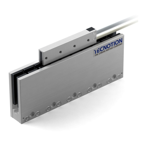
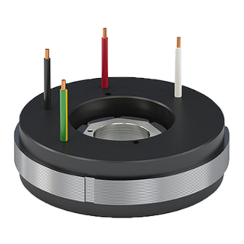
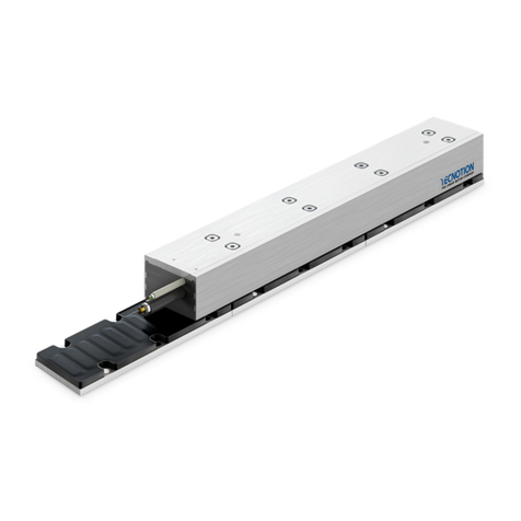
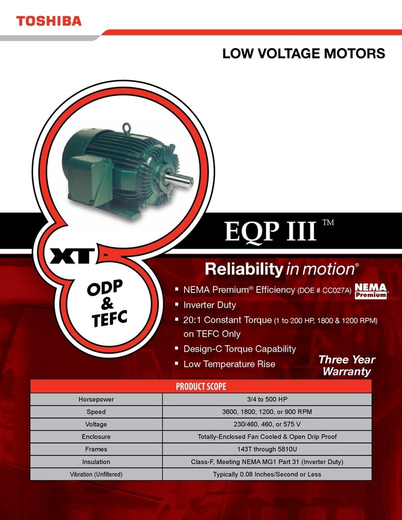
Tecnotion UC Series Instruction Manual

TECNOTION B.V.
PO BOX 23
7600 AA ALMELO
THE NETHERLANDS
Document nr. 4022.363.4197.1
Version 2.1
Issue Date: February 2005
Installing
Tecnotion Ironless Linear
Motors

TECNOTION INSTALLING IRONLESS LINEAR MOTORS
DOCUMENT NR 4022.363.4197.1 1CONTENTS
Contents
Co Contents
Installing Tecnotion Ironless Linear Motors
Contents...................................................................................................................................................1
Introduction ..............................................................................................................................................2
1. Before you start ...............................................................................................................................3
1.1. Important notice....................................................................................................................3
1.2. Safety warnings ....................................................................................................................4
1.3. EC declaration ......................................................................................................................5
2. Components ....................................................................................................................................6
2.1. Basic components................................................................................................................7
2.2. Additional Features ..............................................................................................................8
2.2.1. Bolts and dowel pins........................................................................................................9
2.2.2. Controller and measurement unit ...................................................................................9
2.2.3. Tools...............................................................................................................................10
3. Installation ......................................................................................................................................11
3.1. Installation order .................................................................................................................12
3.2. Requirements for the mounting surfaces..........................................................................13
3.3. Magnet track mounting instructions...................................................................................15
3.4. Coil unit mounting instructions...........................................................................................17
3.5. Electrical Connections........................................................................................................18
3.5.1. General remarks............................................................................................................18
3.5.2. Power lines.....................................................................................................................20
3.5.3. Protective earth..............................................................................................................20
3.5.4. Temperature Sensor .....................................................................................................21
3.5.5. PTC specification...........................................................................................................21
3.5.6. KTY specification ...........................................................................................................22
3.5.7. Polarization test .............................................................................................................23
4. Operation .......................................................................................................................................24
4.1. General ...............................................................................................................................24
4.2. Configuring..........................................................................................................................25
4.3. Testing ................................................................................................................................26
4.3.1. End switches..................................................................................................................26
4.4. Starting up...........................................................................................................................27
4.5. Optimization of control settings..........................................................................................27

TECNOTION INSTALLING IRONLESS LINEAR MOTORS
DOCUMENT NR 4022.363.4197.1 2INTRODUCTION
Intro
IIntroduction
Generally a linear motor system is a part of a specific machine.
Tecnotion’s linear motors can be combined with numerous application
devices. This installation manual is intended for those technicians who
construct a machine that includes a linear motor system
When installing a linear motor system one should be familiar with some
important safety remarks. In the first chapter these remarks are made.
Please, read them carefully.
Besides mounting the coil unit and the magnet plates, the installation
includes the electrical wiring and the connections between the motor
and the servo-controller.
Before starting up, some required settings will be discussed. Finally
your linear motor can take off for it’s first ride.
For further information and support, please contact:
TECNOTION B.V. Telephone: +31(0)546 536 300
PO Box 23 Fax: +31(0)546 536 310
7600 AA Almelo sales@tecnotion.com
The Netherlands www.tecnotion.com

TECNOTION INSTALLING IRONLESS LINEAR MOTORS
DOCUMENT NR 4022.363.4197.1 3BEFORE YOU START
Chapter
Ch 1. Before you start
Please read the following instructions very carefully. They are important
for a safe and warranted installation and operation of the Linear Motor.
1.1. Important notice
Before installing and using the Linear Motor, read this
instruction manual carefully. The manufacturer declines all
responsibility in case of accident or damage due to
negligence or lack of observance of the instructions
described in this manual. The manufacturer also declines all
responsibility in case of accident or damage in conditions
that differ from those indicated in the manual; Tecnotion also
declines all responsibility for damage caused by improper
use of the Linear Motor.
Handle the components of the Linear Motor with care,
packed as well as unpacked. Especially the magnet yokes
are sensitive to mechanical shocks. Never drop a magnet
yoke or release it in an uncontrolled way.
Do not expose the magnets to temperatures higher than
70° C. The magnets may be demagnetized at higher
temperatures.
Unpack the Linear Motor and check its integrity. If there is
any irregularity, contact the dealer or manufacturer,
signalling the nature of the defects.
Make a note of the serial number. This facilitates the
correspondence with the supplier.

TECNOTION INSTALLING IRONLESS LINEAR MOTORS
DOCUMENT NR 4022.363.4197.1 4BEFORE YOU START
1.2. Safety warnings
The Linear Motor is used as a part of a machine. The user
has to take care that the machine as a whole fulfils all CE
requirements.
The magnet yokes contain a strong magnetic field. Lose iron
objects that are brought within 5cm of the yokes, can be
drawn into the yokes and cause damage.
The magnet yokes do attract each other while mounting.
Take care that the closing plates of one yoke do not damage
the magnets of the neighbour magnet yoke while mounting.
If at any time and in any situation there is any doubt about
the safety of the Linear Motor, do not use it and contact your
supplier.
The Linear Motor is powered by a servo amplifier. In case of
a power disruption or fatal error this may automatically result
in a free run out of the motor. Make mechanical precautions
to prevent damage on the motor or your machine in the case
of such an event.
Before installing the motor, make sure that the supply mains
are grounded and operate in conformity with the regulations
in force.

TECNOTION INSTALLING IRONLESS LINEAR MOTORS
DOCUMENT NR 4022.363.4197.1 5BEFORE YOU START
Make sure that there is an effective protective earth. Make
sure that there is no voltage at the line wire terminals before
connecting.
An earth connection does not work on non-conducting
mounting surfaces like granite. In these cases the protective
earth must be established by an earthing wire
Before carrying out checks or doing any maintenance, clear
the system by disconnecting the voltage. Be sure that there
is no possibility of accidental connections.
1.3. EC declaration
Tecnotion B.V. declares that the all linear motors produced by
Tecnotion are manufactured in accordance with the applicable
European directives and in conformity with the following standards:
Standard # Date of issue Name of Standard
EN 60034 05-1998 Rotating electrical machines
EN 60204 (-1) 02-1995 Safety of machinery
EN 50081-2 08-1993 Emission requirements for products in an
industrial environment
EN 50082-2 03-1995 Immunity requirements for products in an
industrial environment

TECNOTION INSTALLING IRONLESS LINEAR MOTORS
DOCUMENT NR 4022.363.4197.1 6COMPONENTS
Chapter
Ch 2. Components
Figure 1: A complete ironless linear motor system
An ironless linear motor of Tecnotion is not a system on itself. It
contains several components, such as a coil unit and magnet yokes.
The components should be build within a total machine concept or a
working unit. The size and the shape of the mounting frame, the design
of the slide, the type bearings or the kind of dampers depend of the
required application. For instance the mounting frame and the slide
should be designed in such a way that a correct air gap between coil
unit and magnet yokes will be obtained.
Tecnotion provides standard and special components which are
suitable for numerous linear motor applications. These components
can easily be applied in your system.

TECNOTION INSTALLING IRONLESS LINEAR MOTORS
DOCUMENT NR 4022.363.4197.1 7COMPONENTS
2.1. Basic components
The basic Linear Motor components supplied by Tecnotion are:
•The coil unit (the N and S version differing in voltage and current
requirements)
Figure 2: Coil unit
•The magnet yoke (in different lengths, varying in outer dimensions
and mounting)
Figure 3: Magnet yoke

TECNOTION INSTALLING IRONLESS LINEAR MOTORS
DOCUMENT NR 4022.363.4197.1 8COMPONENTS
Before starting the installation, check the presence of the
right number and type of the delivered components. In case
of doubt, please contact Tecnotion immediately.
2.2. Additional Features
For a proper installation of your linear motor system you also need
•fixing components, like bolts and pins;
•additional devices, like a servo controller and a linear encoder;
•the right tools.
These features are no part of Tecnotion’s standard delivery. If desired
Tecnotion can supply all additional components as well as some types
of devices.

TECNOTION INSTALLING IRONLESS LINEAR MOTORS
DOCUMENT NR 4022.363.4197.1 9COMPONENTS
2.2.1. Bolts and dowel pins
Figure 4: Dowel pins
The following bolts and dowel pins are required for positioning and
fixing the coil unit to the slide as well as connecting the magnet yokes
to the mounting frame:
Features UC UM UL UX
Bolts for coil unit (steel) M3,
DIN912
M3x16,
DIN912
M4x20,
DIN912
M5x20,
DIN912
Bolts for magnet yoke
(steel)
M4x20,
DIN7984
M4x25,
DIN912
M5x35,
DIN912
M6x40,
DIN912
Dowel pins for magnet
yoke (optional)
3h8,
DIN7
2.2.2. Controller and measurement unit
Required is:
•An appropriate servo controller/amplifier
•A ruler and a linear encoder or an analogue Hall module
•Power supply, cabling and connectors
For more information please contact Tecnotion.

TECNOTION INSTALLING IRONLESS LINEAR MOTORS
DOCUMENT NR 4022.363.4197.1 10 COMPONENTS
2.2.3. Tools
Necessary for the installation is:
•Allen Key set
Occasionally useful are:
•Heat sink compound (optional)
•Wipes to clean mounting surfaces

TECNOTION INSTALLING IRONLESS LINEAR MOTORS
DOCUMENT NR 4022.363.4197.1 11 INSTALLATION
Chapter
Ch 3. Installation

TECNOTION INSTALLING IRONLESS LINEAR MOTORS
DOCUMENT NR 4022.363.4197.1 12 INSTALLATION
3.1. Installation order
Figure 5: Ironless linear motor system
Yoke
Magnet
Coil unit
Slid e
Mounting surface
for magnet track
Figure 6: Coil unit, slide, magnet yoke and mounting surface, schematically
The installation order of this instruction manual must be
followed. A different order may cause damage to your
machine.
Before installing the Linear Motor components, the installation of the
mounting frame should be completed. The slide should be provided
with bearings, dampers, linear probe and required cabling in such a
way that a smooth, save and well positioned transport of the slide over
the stroke is established. The ruler should be properly positioned and
fixed to the frame. The operation of bearings and dampers should be
tested as well as the guidance of the moving cables.
The correct installation order is for electrical safety reasons:

TECNOTION INSTALLING IRONLESS LINEAR MOTORS
DOCUMENT NR 4022.363.4197.1 13 INSTALLATION
1. Mount the magnet yokes to the mounting surface of the machine.
2. Mount the coil unit to the involved machine parts
3. Connect the wiring to the coil unit.
From a magnetical point of view the installation order of the mechanics
is not critical, because no attraction is present between the coil unit and
magnet yokes.
The de-installation order is:
1. Disconnect the wiring from the coil unit.
2. Dismount the coil unit from the machine parts.
3. Dismount the magnet yokes from the machine’s mounting surface
Before mounting the Linear Motor, special attention must be paid tot
the mounting surface of the motor.
3.2. Requirements for the mounting surfaces
A
0.1
0.05 A(p a p e rp la ne o nly)
Figure 7: Flatness and parallelism of mounting surfaces, schematically
The mounting surfaces of both magnet yokes and coil units have to be
flat to prevent them from being submitted to bending forces.

TECNOTION INSTALLING IRONLESS LINEAR MOTORS
DOCUMENT NR 4022.363.4197.1 14 INSTALLATION
Specifications:
•Surface for coil unit having a flatness better then 0.1mm.
•Surface for the track of magnet yokes having a flatness better than
0.1mm.
The track of the magnet yokes – from now on to be called the magnet
track – and the coil unit have to be aligned with respect to each other.
Note that this has to be accomplished by the machine’s construction.
To guarantee a non-contact running, the mounting surfaces of coil unit
and the magnet track must be parallel:
•Parallelism of both surfaces better then 0.05mm in the plane
perpendicular to the travelling direction.
To prevent disturbance forces, the axial direction of both components
should be parallel. This has to be accomplished by supporting axial
references for both the coil unit and the magnet yokes.
•axial references for both coil unit and magnet track with parallelism
better than 0.2mm.
A1
MR
CR
A2
Figure 8: Air gaps and axial references, schematically
Axial reference for the magnet track (MR, see figure above) can be
obtained by the use of
•dowel pins in the middle yoke of a short track,
•dowel pins along the complete side of a long track,

TECNOTION INSTALLING IRONLESS LINEAR MOTORS
DOCUMENT NR 4022.363.4197.1 15 INSTALLATION
•milled reference along complete side of a long track (inner radius <
0.2mm), or
•alignment by hand during mounting.
Axial reference for the coil unit (CR) is obtained by
•two dowel pins beside the first and last bolt of the coil unit,
•milled reference along complete side (inner radius < 0.2mm), or
•alignment by hand during mounting.
Note that only when the right references and dimensions are applied
the right dimensioned air gaps (A1 and A2) will be obtained. The
dimensions of the coil units and magnet yokes can be found on the
internet site of Tecnotion: www.tecnotion.com.
3.3. Magnet track mounting instructions
Especially the magnet yokes must be handled with care.
They are sensitive to mechanical shocks. Never drop a
magnet yoke or release it in an uncontrolled way!
Be sure that the mounting surfaces are free of
contamination. Particles > 0.1mm can cause inaccurate
placement and consequently damage to your Linear Motor.
It is recommended to start the mounting of the magnet track with the
middle – and preferably the longest – magnet yoke. This middle yoke
can be aligned using the 3mm dowel pins or a milled reference.
Fix the magnet yoke on the mounting surface with bolts using the
prescripted tightening torque.

TECNOTION INSTALLING IRONLESS LINEAR MOTORS
DOCUMENT NR 4022.363.4197.1 16 INSTALLATION
The following yokes can be mounted with mechanical contact using the
mutual attraction force of the magnet yokes.
Take care: apply the principle of controlled rotational
mounting. Uncontrolled approach may cause damage to the
magnets (see Figure 9).
Because a straight forward directing and placing of the yokes implies
the risk of striking due to magnetical forces (as well as the risk of
damaged magnets), the principle of rotational mounting is
recommended here.
Yoke 1
Y
oke3
Y
oke 2
Figure 9: Principle of controlled rotational mounting of the magnet yokes
The next magnet yokes should not be aligned on dowel pins. Using a
track of pins has namely two disadvantages:
1. In that situation rotational mounting is difficult.
2. Mounting can be impossible because of tolerances. The yokes are
designed for a contact mounting without guaranteed gap between
them.
Using a milled axial reference is advised for placement of the next
tracks (longer than 200mm).
Placement of just one yoke on each side of the middle yoke can be
done by simply aligning the yokes with respect to each other.
There is no danger of mounting the magnet yokes with an incorrect
orientation, they are “Murphy-safe”. A 180° rotated yoke does not have
any effect on the motor function.

TECNOTION INSTALLING IRONLESS LINEAR MOTORS
DOCUMENT NR 4022.363.4197.1 17 INSTALLATION
3.4. Coil unit mounting instructions
Be sure that the mounting surfaces are free of
contamination. Particles > 0.1mm can cause inaccurate
placement and consequently damage to your Linear Motor.
The mounting of the coil unit on appropriate and clean mounting
surfaces is very straightforward because no attraction forces are
present between coil unit and magnet yokes.
The coil unit can be placed into the machine by hand carefully, pushed
to the axial reference and fixed with bolts. Tightening torque of the bolts
as prescipted.
For applications which are susceptible to vibrations, the
bolts have to be secured against loosening by means of
rings or (Loctite) thread lock.
In case of high continous forces, apply a heatsink compound
to obtain optimal thermal contact between the coil unit and
the mounting surface.

TECNOTION INSTALLING IRONLESS LINEAR MOTORS
DOCUMENT NR 4022.363.4197.1 18 INSTALLATION
3.5. Electrical Connections
Before starting any activity on the wiring, make sure that the
mains are disconnected. Work carefully according the
instructions belonging to the applied servo controller. Be
sure your machine meets the requirements of the EN 60204
standard.
3.5.1. General remarks
The linear motor’s electrical wiring is externally configured with two 1.0
meter cables: a power cable and a temperature cable. If desired you
can shorten these cables and provide them with appropriate
connectors.
Note that the UM, UL and UX cables are not meant for use
within cable chains. For that purpose user defined cables
should be used which meet the specifications concerning
bending radius, length, replacebility, etcetera. Take care of
connecting the motor’s standard cables properly to the user
defined cables.
Only the UC power cable is suited for use within a cable chain.
Both power cable and temperature cable (except UC) are shielded with
a plaited metal cable sheath for electromagnetic immunity.
Besides this manual you should follow carefully the installation
instructions of your servo amplifier supplier. Make sure that the linear
motor system as a whole meets all the applicable electrical directives.

TECNOTION INSTALLING IRONLESS LINEAR MOTORS
DOCUMENT NR 4022.363.4197.1 19 INSTALLATION
For wiring scheme see figure below.
L1
L1
L2
L2
L3
L3
gr/ye
white
brown
ye
green
PE
Line a r
motor
Slid e
PTC
KTY
Se r v o
amplifier
Figure 10: Wiring scheme UM, UL and UX series ironless
L1
L1
L2
L2
L3
L3
gr/ye
PE
Linear
motor
Slid e
Se r v o
am plifier
Figure 11: Wiring scheme UC series ironless
This manual suits for next models
3
Table of contents
Other Tecnotion Engine manuals
Popular Engine manuals by other brands

Hyundai Seasall
Hyundai Seasall U125S Installation & operation manual
Packard
Packard 320725-753 installation instructions
Motolux
Motolux 802311012 Programming instructions
Kubota
Kubota V3600-E3 Operator's manual
PTM Engines
PTM Engines 120F owner's manual

Simple Motors
Simple Motors Kit 11 Assembly instructions
