Tecnoware EVO DSP PLUS TT 15 KVA User manual

Uninterruptible Power Supply
EVO DSP PLUS TT 10 KVA
EVO DSP PLUS TT 15 KVA
EVO DSP PLUS TT 20 KVA
User’s m nu l
M nu le utente


Index
User’s M nu l - English ........................................................................ 1
S fety W rnings ................................................................................. 1
1
Introduction ................................................................................. 2
2
Gener l Ch r cteristics ................................................................... 3
3
Receipt nd site selection ................................................................ 3
4
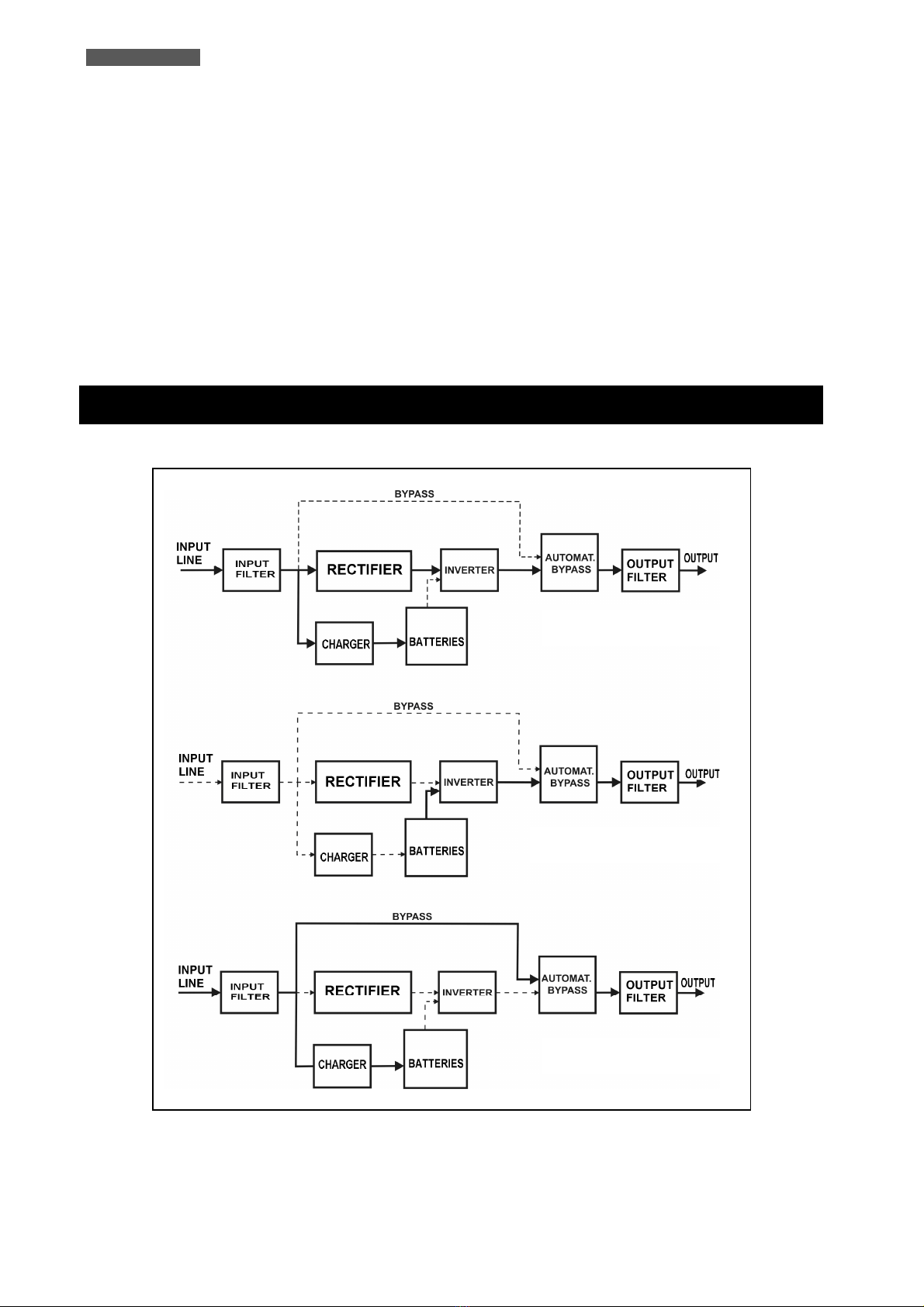
Oper ting Modes ........................................................................... 4
4.1
UPS Power On ......................................................................... 5
4.2
NORMAL Mode ......................................................................... 6
4.3
BATTERY Mode ........................................................................ 6
4.4
BYPASS Mode .......................................................................... 7
4.5
NO-OUTPUT Mode .................................................................... 8
4.6
BATTERY TEST mode .................................................................
4.7
ECO Mode ............................................................................. 10
4.8
CONVERTER FREQUENCY Mode ..................................................... 11
4.
WARNING STATUS .................................................................... 12
4.10
FAULT STATUS ........................................................................ 12
5
Extern l Description ...................................................................... 13
5.1
Front Panel ........................................................................... 13
5.1.1
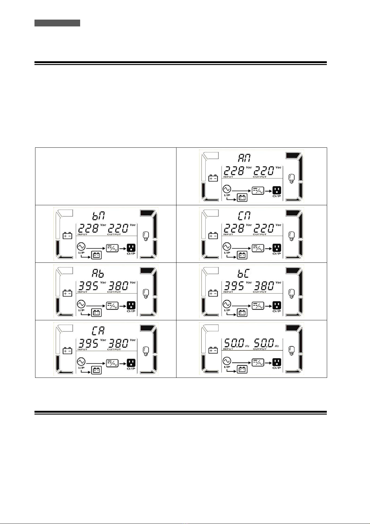
Graphic LCD Panel ....................................................................... 14
5.1.2
Buttons.................................................................................... 16
5.1.3
LED Indicators ............................................................................ 16
5.1.4
Acoustic Alarm ........................................................................... 16
5.2
Rear Side .............................................................................. 17
5.2.1
Input/Output Terminals ................................................................ 18
5.2.2
EPO (Emergency Power Off) ........................................................... 1
6
Electric l Inst ll tion ..................................................................... 19
6.1
Installation ............................................................................ 20
7
First St rt Up ............................................................................... 22
8
Functioning ................................................................................. 22
8.1
Turning ON and OFF ................................................................. 22
8.2
Low Battery and Automatic Restart ............................................... 23
8.3
Load Testing .......................................................................... 23
8.4
Manual Bypass ........................................................................ 24
8.5
Battery Test .......................................................................... 24
8.6
Operation in Warning Status ....................................................... 25
8.7
Operation in Fault Mode ............................................................ 26
8.8
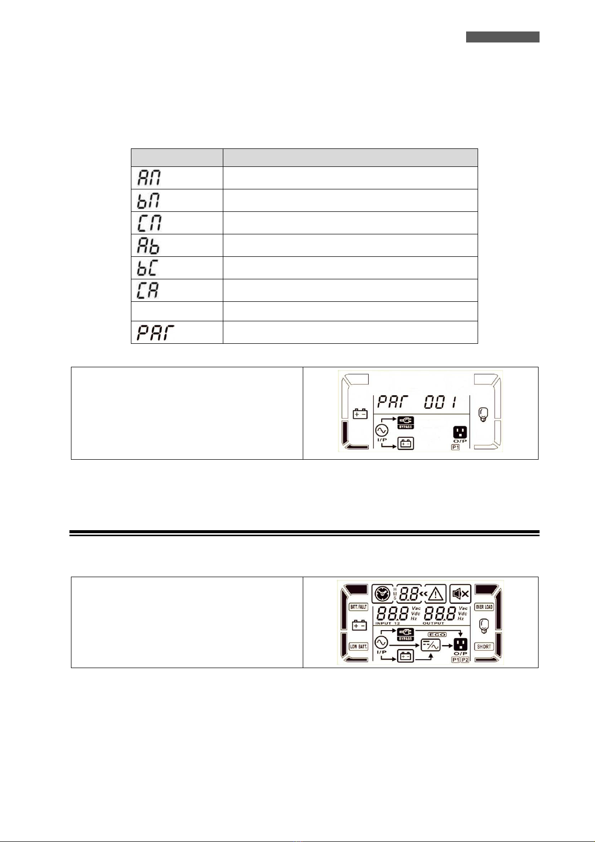
Operating Procedures for Parallel System ........................................ 27
8.8.1
Parallel System Connection ............................................................ 27
8.8.2
Add one new unit into the Parallel System .......................................... 28
8.8.3
Remove one unit from the Parallel System .......................................... 28
9
Communic tion Interf ces ............................................................... 28
10
Technic l Ch r cteristics ................................................................ 29
11
M inten nce ................................................................................ 31
11.1
UPS Cleaning ......................................................................... 31
11.2
Battery ................................................................................ 31
11.3
Operator Safety ...................................................................... 31
12
Troubleshooting ........................................................................... 32
Conformity to the Europe n Directives ................................................... 34
Product Dispos l ............................................................................... 34
Le d B tteries ................................................................................. 34

Indice
M nu le Utente – It li no ................................................................... 35
Avvisi di Sicurezz ............................................................................ 35
1
Introduzione ............................................................................... 36
2
C r tteristiche Gener li................................................................. 37
3
Ricevimento e Colloc zione ............................................................ 37
4
Modi di Funzion mento ................................................................. 38
4.1
Accensione UPS ....................................................................... 3
4.2
Modo NORMALE ....................................................................... 40
4.3
Modo BATTERIA ....................................................................... 40
4.4
Modo BYPASS .......................................................................... 41
4.5
Modo NO-OUTPUT .................................................................... 42
4.6
Modo BATTERY TEST ................................................................. 43
4.7
Modo ECO ............................................................................. 44
4.8
Modo CONVERTITORE DI FREQUENZA .............................................. 45
4.
STATO DI ALLARME ................................................................... 46
4.10
STATO DI GUASTO (FAULT) ......................................................... 46
5
Descrizione Estern ...................................................................... 47
5.1
Pannello Frontale .................................................................... 47
5.1.1
Pannello LCD Grafico .................................................................... 48
5.1.2
Pulsanti .................................................................................... 50
5.1.3
Indicazioni a Led ......................................................................... 50
5.1.4
Allarme Acustico ......................................................................... 50
5.2
Pannello Posteriore .................................................................. 51
5.2.1
Morsettiera d’Ingresso/Uscita .......................................................... 52
5.2.2
EPO (Emergency Power Off) ............................................................ 53
6
Inst ll zione Elettric ................................................................... 53
6.1
Installazione .......................................................................... 54
7
Prim Accensione ......................................................................... 56
8
Funzion mento ........................................................................... 56
8.1
Accensione e Spegnimento ......................................................... 56
8.2
Fine Autonomia e Riaccensione Automatica ...................................... 57
8.3
Controllo del Carico ................................................................. 57
8.4
Bypass Manuale ....................................................................... 58
8.5
Test Batteria .......................................................................... 58
8.6
Segnalazioni di Allarme ............................................................. 5
8.7
Segnalazioni di Guasto .............................................................. 60
8.8
Procedure Operative per Sistemi Parallelo ....................................... 61
8.8.1
Collegamenti per Sistema Parallelo ................................................... 61
8.8.2
Aggiungere un nuovo UPS nel Sistema Parallelo ..................................... 62
8.8.3
Rimuovere un UPS dal Sistema Parallelo.............................................. 62
9
Interf cce di Comunic zione ........................................................... 62
10
C r tteristiche Tecniche ................................................................ 63
11
M nutenzione ............................................................................. 65
11.1
Pulizia dell’UPS ...................................................................... 65
11.2
Batterie ................................................................................ 65
11.3
Sicurezza dell’Operatore ........................................................... 65
12
Anom lie ed Interventi .................................................................. 66
Conformità lle Direttive Europee ........................................................ 68
Sm ltimento del Prodotto ................................................................... 68
B tterie l Piombo ............................................................................ 68

ENGLISH
UPS EVO DSP PLUS TT 1 User’s manual
User’s M nu l - English
S fety W rnings
Re d this m nu l c refully nd completely before inst lling nd using the TECNOWARE EVO DSP
PLUS TT Uninterruptible Power Supply, which, from here fter, will lso be referred to s UPS.
The UPS must be used only by properly tr ined personnel. To ensure correct nd s fe
oper tions, it is necess ry th t oper tors nd m inten nce personnel observe the gener l
s fety St nd rds s well s the specific instructions included in this m nu l.
Risk of electric shock: do not remove the cover. The UPS cont ins intern l p rts which re t
high Volt ge nd re potenti lly d ngerous, c p ble of c using injury or de th by electric
shock.
There re no intern l p rts in the UPS which re user service ble. Any rep ir or m inten nce
work must be performed exclusively by qu lified technic l personnel uthorized by
TECNOWARE. TECNOWARE declines ny responsibility if this w rning is disreg rded.
The electric inst ll tion h s to be done by qu lified personnel. Follow ll the S fety St nd rds
(CEI St nd rds in It ly or IEEE elsewhere) for the Input/Output connections nd for the right
section of Input/Output c bles.
It is compulsory to ground the UPS ccording to S fety St nd rds.
Risk of electric shock t the Output lines when the UPS is ON.
Risk of electric shock t the Output lines while the unit is connected to the AC utility line.
For respect of the S fety St nd rds is necess ry the presence of differenti l circuit bre ker
between UPS Output lines nd the lo ds.
We recommend to use dedic te AC Input/Output power line for the UPS.
Do not obstruct ventil tion slots or holes nd do not rest ny object on top of the UPS.
Do not insert objects or pour liquids in the ventil tion holes.
Inst ll the UPS indoors, in protected, cle n nd moisture-free environment.
Do not expose to the direct sun light.
Do not keep liquids, fl mm ble g ses or corrosive subst nces ne r the UPS.

ENGLISH
User’s manual 2 UPS EVO DSP PLUS TT
1Introduction
UPS EVO DSP PLUS TT (UPS means Uninterruptible Power Supply) is the result of constant technological research
aimed at obtaining the best performance at the lowest cost.
UPS EVO DSP PLUS TT is an advanced ON-LINE UPS built specifically to protect your computer from any
irregularities in the AC line (for example blackouts, brownouts, over voltages, micro-interruptions), which often
cause damage to hardware and software.
All that is possible because UPS EVO DSP PLUS TT is a Double-Conversion ON-LINE UPS.
Under normal AC line condition UPS EVO DSP PLUS TT provides an automatic Output Voltage regulation from the
Rectifier and Inverter blocks and filters out frequently occurring electrical disturbances (high Voltage transients,
spikes, interferences, etc.), thus protecting the devices connected to its outlets. During a power failure, UPS EVO
DSP PLUS TT continues supplying adequate AC power (with a true sine wave) to all connected devices through its
internal batteries and by its DC/AC converter (Inverter).
UPS EVO DSP PLUS TT protects the devices from accidental overload or Inverter fault by an Automatic Bypass that
directly connects the AC Input line with its outlets.
UPS EVO DSP PLUS TT models are factory-equipped with RS-232 and USB interfaces, which may be used for notify
to a computer a power failure or a Low Battery condition: this allows automatic data backup during an extended
blackout with the most common operating systems (Windows, Linux, Unix, etc). Thanks to Interfaces, UPS EVO DSP
PLUS TT can communicate the several made measurements (Input/Output Voltage, batteries, absorption,
Frequency, etc.), and can also be programmed in order to start-up or shutdown automatically at fixed times.
Re d this m nu l c refully before using the UPS EVO DSP PLUS TT; it includes import nt
s fety w rnings nd useful dvices for correct use nd inst ll tion.
UPS EVO DSP PLUS TT is constantly being developed and improved: consequently, your unit may differ somewhat
from the description contained in this manual.
This manual includes the following models:
•UPS EVO DSP PLUS TT 10 KVA
•UPS EVO DSP PLUS TT 15 KVA
•UPS EVO DSP PLUS TT 20 KVA
In this manual UPS EVO DSP PLUS TT will simply be referred to as UPS.
EVO DSP PLUS TT models are made from a single unit that contains the electronics parts and the batteries.
However EVO DSP PLUS TT models are predisposed to the connection with external BATTERY BOX units in order to
increase the autonomy.

ENGLISH
UPS EVO DSP PLUS TT 3 User’s manual
2Gener l Ch r cteristics
UPS EVO DSP PLUS TT has all the advanced features, which guarantee maximum reliability and safety:
•Double-Conversion ON-LINE Transformerless technology
•Sinusoidal wave generated by an IGBT Inverter
•Output Voltage regulation ±1%
•Protection from overload and short circuits
•Automatic Bypass to protect from accidental overload or Inverter fault
•Start-up even under Mains OFF conditions
•Automatic protection when Battery is low
•Automatic restart, following an automatic shut-down due to Low Battery, once AC utility power comes
back on
•Selectable Input Frequency (50/60 Hz)
•Graphic LCD panel for visualization of the Input and Output Voltage measurements, batteries Voltage,
percentage of load, Frequency, alarms, overload, fault and path of energy flow
•Acoustic signals of various kinds indicating alarm situations
•Available settings of all the UPS parameters by user through front panel pushbuttons and graphic LCD
panel
•SNMP Adapter (optional)
•EPO (Emergency Power OFF)
•Communication with the computer through RS-232 and USB interfaces
•Available extended autonomy by adding external Battery Boxes
•Manual Bypass for maintenance
•Parallel operating mode up to 3 UPS’s (optional)
•ECO functioning mode (selectable)
•Frequency Converter functioning mode (selectable)
•High efficiency
•Maximum reliability
•Smart design and easy to use
3Receipt nd site selection
Carefully remove the UPS from its packaging, and carry out a meticulous inspection. We recommend keeping the
original packaging in a secure place, in case you need to send the UPS for maintenance purposes. In case of
transport damage, notify the carrier and dealer immediately.
We recommend paying attention to the below points in order to choose a correct placement for your UPS:
•The UPS is designed to operate in a protected environment (e.g. offices). We therefore recommend
installing it in a place with very little or no humidity, dust or smoke.
•When the UPS is brought from a cold place to a warmer place, humidity in the air may cause condensation
in the UPS. In this case, allow UPS to stand for two hours in the warmer place before beginning with the
installation.

ENGLISH
User’s manual 4 UPS EVO DSP PLUS TT
•In all circumstances, see the “Technical Characteristics” chapter for environmental specifications and
check that the selected area meets these criteria.
•During normal operation the UPS discharges a minimal amount of heat. So it is necessary to leave at least
25 cm of unobstructed space all around the UPS in order to keep it properly ventilated.
•Do not obstruct ventilation holes.
•Do not insert objects or pour liquids in the ventilation holes.
•Do not rest any object on top of the UPS.
•Do not keep liquids, flammable gases or corrosive substances near the unit.
•Install the UPS on a properly tiled floor. Avoid the installation on a floor that is not tiled flat.
4Oper ting Modes
Figure 1 – Oper ting modes
BATTERY MODE
NORMAL MODE
BYPASS MODE

ENGLISH
UPS EVO DSP PLUS TT 5 User’s manual
Following pages shows LCD display for operating modes and status.
If the UPS is in normal operation, it will show seven screens one by one, which represents 3 Phase Input/Output
voltages (AN, bN, CN), 3 Line Input/Output voltages (Ab, bC, CA) and frequency in turns (see the table below).
Displ y P r meter V lue
L1 Phase-Neutral Voltage (Input/Output)
L2 Phase-Neutral Voltage (Input/Output)
L3 Phase-Neutral Voltage (Input/Output)
L1 Phase-L2 Phase Voltage (Input/Output)
L2 Phase-L3 Phase Voltage (Input/Output)
L3 Phase-L1 Phase Voltage (Input/Output)
No parameter
Frequency (Input/Output)
Parallel UPS Systems, “001” means the master UPS
If Parallel UPS Systems are successfully set up, it will
show one more screen with “PAR”.
The master UPS will be default assigned as “001” and
slave UPSs will be assigned as either “002” or “003”.
The assigned numbers may be changed dynamically in
the operation
P r llel screen
4.1 UPS Power On
When UPS is powered on, it will enter into this mode for a few seconds as initializing the CPU and system.
All the icons on the graphic LCD panel are ON.
All the leds are ON.

ENGLISH
User’s manual 6 UPS EVO DSP PLUS TT
4.2 NORMAL Mode
The UPS typically works in Normal mode: Input mains power is available and its amplitude is within specifications.
Please refer to figure 1.
After the filter has eliminated any high Frequency interference present on the mains, the AC Input line is rectified
and conditioned in the Rectifier block (AC/DC conversion); the continuous power now enters into the Inverter
block and is then reconverted into alternated power (DC/AC conversion), overcoming the Automatic Bypass and
feeding the load after an extra filtration. At the same time the UPS recharges the batteries through the Battery
Charger block.
Please refer to figure 2, which describe the UPS front panel.
The Normal mode is identified by:
1. Line led is ON.
2. The graphic LCD panel shows the path of energy
flow during Normal mode.
4.3 BATTERY Mode
During operation in Normal mode, if the UPS finds the Mains OFF condition (due to a Blackout or
Overvoltage/Brownout), it then switches into Battery mode. In this case, the batteries supply the required Output
power thanks to the DC/AC conversion carried out by the Inverter. The UPS switches back to Normal mode a few
seconds after AC Input power is restored or Voltage comes back to internal specifications.
Please refer to figure 1.

ENGLISH
UPS EVO DSP PLUS TT 7 User’s manual
The Battery mode is identified by:
1. B ttery led is ON.
2. The graphic LCD panel shows the path of energy
flow during Battery mode.
3. An acoustic signal every 4 seconds.
4.4 BYPASS Mode
In Bypass mode, the AC Input line is directly connected with the UPS outlets by an Automatic Bypass.
As indicated in figure 1, in Bypass mode the UPS recharges the batteries.
If you connect the AC Input line to the UPS and the Input line breaker on the rear is “ON”, the UPS will go to
Bypass mode.
The Bypass mode is an idle mode for the UPS: then by pressing ON button, the UPS turns ON completely,
activating the Inverter block.
When the UPS works in Bypass mode it can be considered as “not active”, since the Inverter block is not active.
The UPS is considered “active” when the Inverter block is ON (in Normal mode and in Battery mode).
Furthermore the UPS switches utom tic lly to Byp ss mode s consequence of ccident l overlo d or
Inverter f ult thus protecting the supplied devices.

ENGLISH
User’s manual 8 UPS EVO DSP PLUS TT
The Bypass mode is identified by:
1. Byp ss led is ON.
2. The graphic LCD panel shows the path of energy
flow during Bypass mode.
3. An acoustic signal every 2 minutes.
During Byp ss mode, lo ds re fed directly from AC Input line. Therefore no protection
g inst AC Input line disturb nces or interruptions is present.
4.5 NO-OUTPUT Mode
When Bypass voltage/frequency is out of acceptable range or Bypass is disabled, UPS will enter into No-Output
mode if powering on or turning off the UPS. It means the UPS has no output.

ENGLISH
UPS EVO DSP PLUS TT 9 User’s manual
The No-Output mode is identified by:
1. All he leds are OFF.
2. The graphic LCD panel shows the path of energy
flow during No-Output mode.
3. An acoustic signal every 2 minutes.
4.6 BATTERY TEST mode
When UPS is in AC mode or CVCF mode, press “Test” key for more than 0.5s. Then, the UPS will beep once and
start the Battery Test mode. The line between I/P and inverter icons will blink to remind users. This operation is
used to check the battery status.
The Battery Test mode is identified by:
1. B ttery, Line and Byp ss leds are ON.
2. The graphic LCD panel shows the path of energy
flow during Battery Test mode.

ENGLISH
User’s manual 10 UPS EVO DSP PLUS TT
4.7 ECO Mode
It is possible to select the ECO mode to save energy and to increase the efficiency of the UPS.
The ECO mode uses the Bypass to feed the loads. The UPS will operate as in Bypass mode whenever the
Frequency/waveform/RMS value of AC Input line mains Voltage is within their tolerance limits. If the AC Input line
Voltage goes beyond these limits, the UPS switches into normal operation.
Please contact Technical Service for the instruction to enable the ECO mode; by default ECO mode is disable.
ECO mode does not provide perfect st bility in Frequency/w veform/RMS v lue of the
Output Volt ge like in Norm l mode. Thus, the use of this mode should be c refully
executed ccording to the level of protection required by the pplic tion.
The ECO mode is identified by:
1. Byp ss and Line leds are ON.
2. The graphic LCD panel shows the path of energy
flow during ECO mode (the “ECO” icon is ON).

ENGLISH
UPS EVO DSP PLUS TT 11 User’s manual
4.8 CONVERTER FREQUENCY Mode
It is possible to select the Converter Frequency mode to work with the Output Frequency different from the Input
Frequency. For example it is possible to work with 60 Hz Input Frequency and 50 Hz Output Frequency or 50Hz
Input Frequency and 60 Hz Output Frequency.
Please contact Technical Service for the instruction to enable the Converter Frequency mode; by default
Converter Frequency mode is disable, and the Output Frequency will synchronize automatically with the Input
Frequency.
The Converter Frequency mode is identified by:
1. Line led is ON.
2. The graphic LCD panel shows the path of energy flow
during Converter Frequency mode.
3. The “CF” characters are ON together with the
Input/Output frequency.

ENGLISH
User’s manual 12 UPS EVO DSP PLUS TT
4.9 WARNING STATUS
If some errors occur in the UPS (but it is still running normally), it will show one more screen to represent the
warning situation. In the warning screen, the icon will be flashing, and it can show up to 3 error codes and
each code indicates one error. You can find the code meaning in the warning code table (see 8.6 chapter).
The Warning Status is identified by:
1. Line led is ON.
2. The graphic LCD panel shows the path of energy flow
during Warning Status.
3. An acoustic signal every second.
4.10 FAULT STATUS
When UPS has fault happened, the inverter will be blocked. It will display Fault code in screen, and the icon
will light up. You can find the code meaning in the Fault code table (see 8.7 chapter).
The Fault Status is identified by:
1. F ult led is ON.
2. The graphic LCD panel shows the path of energy flow
during Fault Status.
3. A continuous acoustic signal.

ENGLISH
UPS EVO DSP PLUS TT 13 User’s manual
5Extern l Description
5.1 Front P nel
The front panel informs the user about operating status, alarm conditions and measurements. It also provides
access to controls and configuration parameters.
Front panel shown below consists of three parts:
1. Graphic LCD panel provides complete information about the energy flow path and existing alarms, Load and
Battery level, Input, Output and Battery measurements.
2. 4 LEDs when illuminated indicate UPS status.
3. 4 buttons enable the user to turn ON/OFF the UPS and to make selections of the functioning parameters.
Figure 2 – Front p nel
Bypass
Line
Battery
Fault
OFF
TEST
MUTE
ON

ENGLISH
User’s manual 14 UPS EVO DSP PLUS TT
5.1.1 Gr phic LCD P nel
Please refer to figure 3.
Figure 3 – Gr phic LCD P nel
Gr phic LCD P nel Function
B ckup time inform tion
Indicates how much time has passed in Battery mode.
H: hours, M: minutes, S: seconds
F ult inform tion
Indicates the warning that a fault has occurred.
Indicates the Fault codes, and the codes are listed in the “Fault Table” of chapter
8.
Mute oper tion
Indicates that the UPS alarm is disabled (muted).
Output Volt ge inform tion
Indicates the Output Voltage or Frequency.
Vac: Output Voltage - Hz: Output Frequency
B ttery
Info
Mode Oper tion
Info
Input & B ttery
Volt ge Info
Output
Volt ge Info
Lo d
Info
B ckup Time
Info F ult Info Buzzer Info
Progr mm ble
Output
Info

ENGLISH
UPS EVO DSP PLUS TT 15 User’s manual
Gr phic LCD P nel Function
Lo d inform tion
Indicates the load level by 0-25%, 26-50%, 51-75%, and 76-100%.
Indicates Overload.
Indicates the load or the Output is short-circuited
Mode oper tion inform tion
Indicates the UPS connects to the mains.
Indicates the Battery is working.
Indicates the Bypass circuit is working.
Indicates the ECO mode is enabled.
Indicates the Inverter circuit is working.
Indicates the Output is working.
B ttery inform tion
Indicates the Battery capacity by 0-25%, 26-50%, 51-75%, and 76-100%.
Indicates the Battery is faulty or defective.
Indicates Low Battery level and Low Battery Voltage.
Input nd B ttery Volt ge inform tion
Indicates the Input Voltage or Frequency or Battery Voltage.
Vac: Input Voltage - Vdc: Battery Voltage - Hz: Input Frequency

ENGLISH
User’s manual 16 UPS EVO DSP PLUS TT
5.1.2 Buttons
Functions of the buttons are given below:
Button Function
ON Turn ON: press and hold the button more than 0.5 sec to turn the UPS ON.
OFF Turn OFF: press and hold the button more than 0.5 sec to turn the UPS OFF.
TEST Battery Test: press and hold the button more than 0.5 sec to test the Battery while in Normal
mode.
MUTE Mute the alarm: press and hold the button more than 0.5 sec to mute the buzzer. If you press it
again after the buzzer is muted, the buzzer will beep again.
5.1.3 LED Indic tors
There are 4 LEDs on the front panel to show the UPS working status:
St tus LED Byp ss Line B ttery F ult
UPS Power On
● ● ● ●
NORMAL Mode
○ ● ○ ○
BATTERY Mode
○ ○ ● ○
BYPASS Mode
● ○ ○ ○
NO-OUTPUT Mode
○ ○ ○ ○
BATTERY TEST Mode
● ● ● ○
ECO Mode
● ● ○ ○
FREQUENCY CONVERTER Mode
○ ● ○ ○
FAULT St tus
○ ○ ○ ●
Note:
●
means LED is lit (ON) and
○
means LED is not lit (OFF).
5.1.4 Acoustic Al rm
Description Buzzer St tus OFF
UPS st tus
Bypass Mode Beeping once every 2 minutes
YES Battery Mode Beeping once every 4 seconds
Fault Mode Beeping continuously
W rning
Overload Beeping twice every second NO
Others Beeping once every second
F ult
All Beeping continuously YES
Note: OFF = YES means that the buzzer can be muted or stopped
OFF = NO means that the buzzer can NOT be muted or stopped
This manual suits for next models
2
Table of contents
Languages:
Other Tecnoware Power Supply manuals
Popular Power Supply manuals by other brands

Pulsar
Pulsar BLACK POWER PSBEN 5012E/LCD manual

SRS Light Design
SRS Light Design WPSU240-8 instruction manual

HP
HP ProCurve 1600M Installation and Removal

Konica Minolta
Konica Minolta MK-734 installation manual

Keysight Technologies
Keysight Technologies E36100B Series Operating and service guide

bonitron
bonitron M3628ACF Customer Reference Manual