ATEQ CDF7000 User manual

RM_CDF7000_315.00_EN_01_2022-12-01
CDF7000
User manual

RM_CDF7000_315.00_EN_01_2022-12-01
1/33
Table of Contents
Safety instructions / Warranty .................................................................................4
GOOD PRACTICES AND SAFETY INSTRUCTIONS............................................................4
AIR QUALITY REQUIREMENTS............................................................................................5
Introduction...............................................................................................................6
ATEQ CDF7000, MULTI-RANGE LEAKAGE CALIBRATOR ...............................................6
FLOW TEST............................................................................................................................6
Measurement principle..................................................................................................6
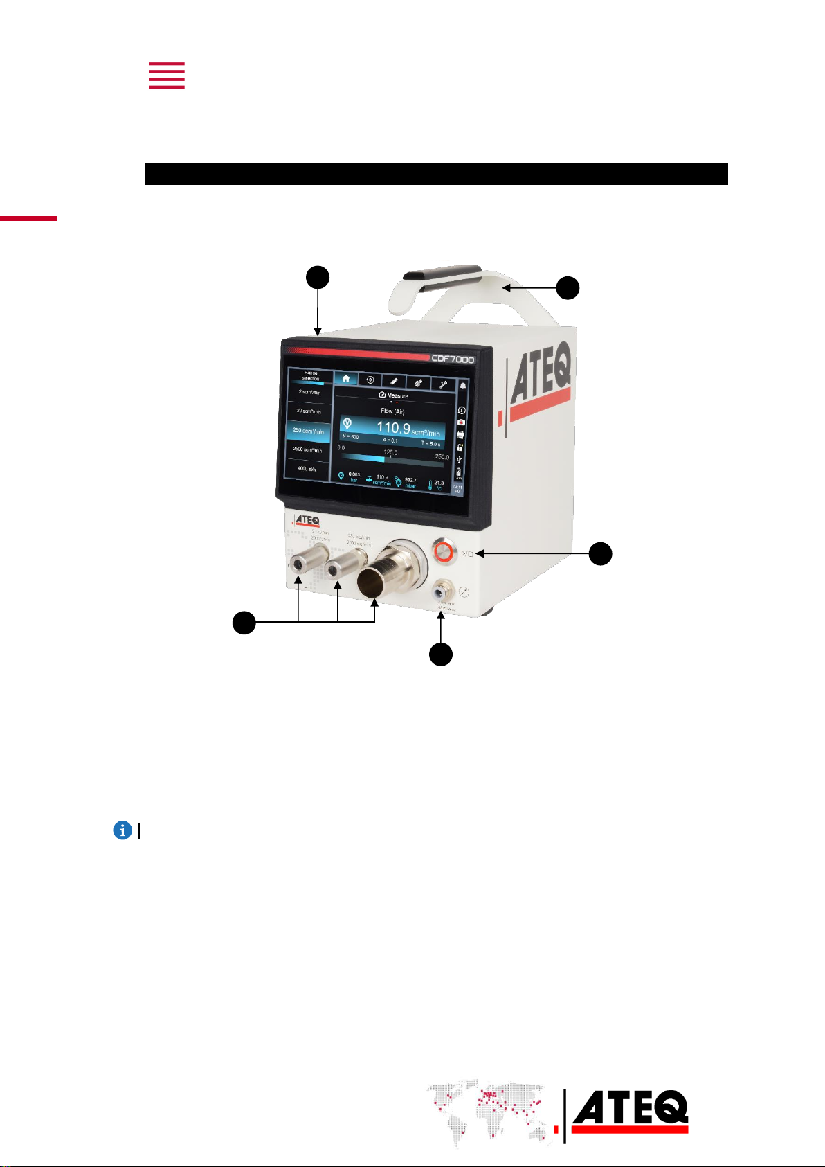
Your ATEQ CDF7000.................................................................................................7
FRONT PANEL .......................................................................................................................7
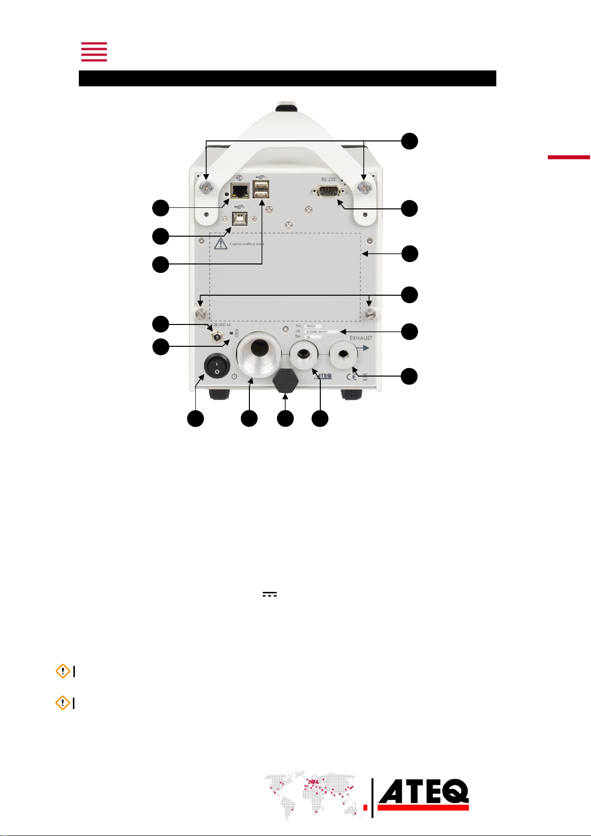
REAR PANEL .........................................................................................................................8
POWER SUPPLY CONNECTOR ...........................................................................................9
External power supply...................................................................................................9
DIGITAL CONNECTIONS.....................................................................................................10
PC USB connector........................................................................................................10
RS232 connector ..........................................................................................................11
Ethernet connector (option).......................................................................................11
PNEUMATIC CONFIGURATION..........................................................................................12
Pressure measurement...............................................................................................12
Leakage measurement................................................................................................12
Leakage calibration......................................................................................................13
User interface..........................................................................................................14
INTRODUCTION ...................................................................................................................14
BUTTON................................................................................................................................14
Cycle button...................................................................................................................14
DISPLAY ...............................................................................................................................15
HOME screen (Standby mode)..................................................................................15
HOME screen (in Measurement mode)...................................................................17
Start-up....................................................................................................................19
POWERING UP.....................................................................................................................19
RANGE SELECTION ............................................................................................................19
STARTING AND STOPPING MEASUREMENTS................................................................20
Starting the measurement..........................................................................................20
Stopping the measurement........................................................................................20
AUTO-ZERO .........................................................................................................................20
User settings...........................................................................................................21
SETTINGS MENU .................................................................................................................21
Available settings.........................................................................................................22

2/33
RM_CDF7000_315.00_EN_01_2022-12-01
Changing units............................................................................................................. 23
Switching to standard units and settings ............................................................. 23
Measurement filters..................................................................................................... 23
Selecting the gas type................................................................................................ 24
CONFIGURATION MENU.................................................................................................... 25
IS/SAE units................................................................................................................... 25
Automatic auto-zero.................................................................................................... 26
Exporting data.............................................................................................................. 26
CSV separator............................................................................................................... 26
Standby........................................................................................................................... 26
MAINTENANCE MENU........................................................................................................ 27
Reset ............................................................................................................................... 27
Valve control................................................................................................................. 27
Calibration date............................................................................................................ 28
STATUS ICONS ................................................................................................................... 28
Notification.................................................................................................................... 28
Screen shot ................................................................................................................... 28
Information.................................................................................................................... 28
Export.............................................................................................................................. 28
Time................................................................................................................................. 28
Alarm message........................................................................................................29
PRESSURE –FULL-SCALE EXCEEDED........................................................................... 29
FLOW RATE –FULL-SCALE EXCEEDED......................................................................... 29
CALIBRATION DATE OVERRUN ....................................................................................... 30
FLOW RATE WARNING...................................................................................................... 31
PRESSURE WARNING........................................................................................................ 31
Maintenance and servicing.....................................................................................32
Cleaning instructions.................................................................................................. 32
Handling precautions.................................................................................................. 32
Recycling ....................................................................................................................... 32
Technical characteristics .......................................................................................33

RM_CDF7000_315.00_EN_01_2022-12-01
3/33
ATEQ –Measurement Solution, Global Leader.
We are working continuously to improve our products. So the information contained in this
manual, the device and the technical specifications may be modified without prior notification.
The images and illustrations in this manual are non-contractual.
ATEQ
15, rue des Dames, Z.I.
78340 LES CLAYES-SOUS-BOIS
FRANCE
ateq.com
Tel. +33 1 30 80 1020
Fax: +33 1 30 54 1100
ATEQ K.K.
3 –41 ATEQ Building, Ikehata
Chiryū, Aichi pref.
JAPAN
ateq.co.jp
Tel: +81 566 84 4670
Fax: +81 566 84 4680
ATEQ China
98 Jian Peng Lu
Shanghai
CHINA
shanghai@ateq.com.cn
ateq.com.cn
Tel: +86 21 6763 9508
Fax: +86 21 6763 9528
ATEQ SYSTEMS ANALYSIS TAIWAN CO.,
LTD.
No. 3, LAN 223, San Jia Dong Street
40642, TAICHUNG
TAIWAN
ateqtaiwan@ateq.com.tw
ateq.com.tw
Tel: +886 4 2437 5278
Fax: +886 4 2437 3675
ATEQ CORP.
35980 Industrial Road Suite L
Livonia, MI 48150
UNITED STATES
leaktest@atequsa.com
atequsa.com
Tel: +1 734 838 3100
Fax: +1 734 838 0644

4/33
RM_CDF7000_315.00_EN_01_2022-12-01
Safety instructions / Warranty
GOOD PRACTICES AND SAFETY INSTRUCTIONS
Safety recommendations
The power supply provided with the device must be used to recharge the battery or to
operate the device directly connected to the mains.
For safety and quality purposes, the unit must be supplied with air at a minimum operating
pressure (0.6 MPa ± 15%) before being powered up.
Recommendations for the test environment
Keep the test area as clean as possible.
Recommendations for operators
ATEQ recommends that operators using the devices are trained and have a level of
qualification that corresponds to the work to be carried out.
General recommendations
—Read the user manual before using the device.
—All electrical connections to the device must be equipped with safety systems (fuses,
circuit breakers, etc.) suited to the needs and in compliance with the applicable standards
and rules.
—To avoid electromagnetic interference, electrical connections to the device should be
shorter than 2 m.
—The power supply plug must be earthed.
—Disconnect the device from the mains before carrying out any maintenance work.
—Shut off the compressed air supply when working on the pneumatic assembly.
—Never open a connected device.
—Avoid splashing water on the device.
—Do not drop the device when moving it.
—Do not place the device on its front panel.
ATEQ is ready to give any information about using the device in optimum safety conditions.
Please note that ATEQ cannot be held responsible for any accident related to misuse of the
measuring instrument or the workstation or to non-compliance of the installation with the
safety rules.
Furthermore, ATEQ declines any responsibility for the calibration or installation of their
instruments that is not carried out by ATEQ.
ATEQ also declines any responsibility for any modification (program, mechanical or electrical)
of the device carried out without their written consent.

RM_CDF7000_315.00_EN_01_2022-12-01
5/33
AIR QUALITY REQUIREMENTS
Air quality requirements according to ISO 8573
The air must be clean and dry.
The presence of impurities, oil or humidity in the air can lead to deterioration which is not
covered by the warranty.
When the instrument is used in a vacuum, prevent impurities from getting inside.
We strongly recommend that a suitable airtight filter is installed between the tested part and
the instrument.
ATEQ specifies the following for the air supply to the device.
Recommended additional equipment
ATEQ recommends the installation of the following additional equipment:
—An air dryer to supply air at less than -40°C dew point.
—Double filter, 25 micron and 1/100 micron.
Air characteristics
ISO 8573 class
Particle size and concentration
0.1 μm and 0.1 mg/m3
Class 1
Dew point under pressure
- 40°C dew point
Class 2
Maximum concentration of oil
0.01 mg/m3
Class 1

6/33
RM_CDF7000_315.00_EN_01_2022-12-01
Introduction
ATEQ CDF7000, MULTI-RANGE LEAKAGE CALIBRATOR
The ATEQ CDF7000 is a multi-range flowmeter for calibrating leakage devices, especially
ATEQ devices.
FLOW TEST
Measurement principle
The ATEQ CDF7000 measures a pressure drop using a differential sensor, at the terminals of
a calibrated pneumatic orifice. It can also be used to check a leakage or a calibrated jet.
Connexion avec
l'appareil à tester
Atmosphère
Capteur de
pression différentiel

RM_CDF7000_315.00_EN_01_2022-12-01
7/33
Your ATEQ CDF7000
FRONT PANEL
The user interface is located on the front panel.
1. Touch screen.
2. Removable handle.
3. Cycle button (START/RESET)
4. Quick connect for pressure measurement.
5. Flow rate measurement connections.
For more information, refer to the User Interface chapter.
1
3
4
5
2

8/33
RM_CDF7000_315.00_EN_01_2022-12-01
REAR PANEL
1. Handle screws.
2. RS232 connector for Printer / Modbus (option) or Profibus (option)
3. Space for internal battery.
4. Cover screws.
5. Part number/Serial number.
6. Capillary exhaust 2–20 cc/min.
7. Capillary exhaust 250–2500 cc/min.
8. Protective stop.
9. Optional capillary exhausts.
10. Main ON/OFF switch.
11. Charging LED.
12. Connector for power supply 28 VDC 4A/h.
13. USB A connector.
14. USB B connector.
15. Ethernet connector.
NB Check that the two handle screws are tight before lifting the device.
Leave enough space at the back of the device for quick access to the main switch.
3
4
1
15
14
13
2
5
11
12
7
10
6
9
8

RM_CDF7000_315.00_EN_01_2022-12-01
9/33
POWER SUPPLY CONNECTOR
The device has a 24 V lithium-ion battery with 8 hours life.
It takes 3 hours to recharge the battery.
External power supply
24 VDC connector
For charging purposes, connect the device to an external
power supply (28 VDC 4 A), using a 2.5 mm jack.
The external power supply of the previous version of the CDF device cannot be used with the
CDF7000.
NB Do not use any power supply other than the one provided by ATEQ.
Charging
When the charger is not connected, the LED is off.
When the charger is connected, the LED comes on:
- It is red if the battery is charging.
- It is green if the battery is already charged.
When the charger is connected and the battery reaches full charge, the LED goes from red
to green.
Main ON/OFF switch
I On
OOff

10/33
RM_CDF7000_315.00_EN_01_2022-12-01
DIGITAL CONNECTIONS
PC USB connector
USB connectors can be used for connecting miscellaneous compatible USB devices.
The USB connectors are on the rear of the device (see illustration).
USB connector to PC
USB connector to USB key
Do not connect two USB devices at the same time.
Do not use a cable longer than 2 m.
Only use this connection for temporary communication.
Connection to a PC cannot be used permanently because the communication can be
disconnected by the PC.

RM_CDF7000_315.00_EN_01_2022-12-01
11/33
RS232 connector
RS232 - 9-pin male SubD connector
For Printer, Modbus (option) or Profibus (option).
RS232 for printer, barcode reader, PC connection.
Ethernet connector (option)
Standard connection Ethernet TCP / IP protocol.
One of these network protocols is available:
—Ethernet.
—Profinet.
—Ethercat.
Pin number
Signal
1
Not used.
2
RXD data input.
3
TXD data input.
4
Not used.
5
Ground.
6
Not used.
7
RTS request to send.
8
CTS clear to send.
9
Not used.
1
5
6
9

12/33
RM_CDF7000_315.00_EN_01_2022-12-01
PNEUMATIC CONFIGURATION
The leakage calibrator can perform a pressure measurement and a leakage measurement.
Pressure measurement
Connect to the pressure circuit of the device under test.
Circuit of the device under test
Leakage measurement
Connect to the measuring circuit of the device under test.
The leakage calibrator has two (or three, depending on options) connections for the leakage
test outlet:
•One connection for low flow rates (0.001 –20.00 mL/min),
•One connection for high flow rates (20.00 to 2500 ml/min).
•A 3rd optional connection allows different flow rates to be measured according to the
size selected (150 l/h, 4000 l/h, 10,000 l/h or 20,000 l/h).
Circuit of the device under test

RM_CDF7000_315.00_EN_01_2022-12-01
13/33
Leakage calibration
STANDARD LEAKAGE
Test
pressure

14/33
RM_CDF7000_315.00_EN_01_2022-12-01
User interface
INTRODUCTION
The front user interface has a touch screen and a user button.
1. Touch screen.
2. Cycle button (START/RESET)
BUTTON
Cycle button
The cycle button starts and stops the measurement.
In Standby mode, the button is green.
Status
Name
Function
Start
Press the button to start the measurement and display
the bar chart measurements.
Stop
Stops the current measurement and returns to the
Standby screen.
1
2

RM_CDF7000_315.00_EN_01_2022-12-01
15/33
DISPLAY
The device has a home screen that changes, depending on the various processes.
HOME screen (Standby mode)
1. Range selection.
2. Navigation tool.
3. Status icon/shortcuts.
4. Measurement display area.
Navigation tools
No.
Button
Description
1
HOME
Returns directly to the home screen.
2
AUTO-ZERO
Manual start of an auto-zero phase.
3
SETTINGS
Measurement settings.
4
CONFIGURATION
Goes to device main configuration menu.
5
MAINTENANCE
Goes to device maintenance information.
1
3
2
4
1
2
3
4
5

16/33
RM_CDF7000_315.00_EN_01_2022-12-01
Status icons/Shortcuts
No.
Button
Description
1
NOTIFICATIONS
Notification indication / Shortcut to
notifications.
2
INFORMATION
Shortcut to device information
(configuration).
3
SCREEN CAPTURE
Takes a screen shot of the live screen
(in ATEQ mode).
4
EXPORT
Shortcut to export settings.
5
UNLOCKING
Indicates that the ATEQ settings are
unlocked.
6
USB
Indication that the USB connection is active
/ Shortcut to port configuration.
7
BATTERY GAUGE
Indication of battery level / Shortcut to
battery information.
8
TIME
Indication of time / Shortcut to time and
date setting.
1
2
3
4
5
6
7
8

RM_CDF7000_315.00_EN_01_2022-12-01
17/33
HOME screen (in Measurement mode)
The measurement screen displays the current measurement. The device measures
continuously and displays the measurements from the various sensors
Bar chart display
1. Type of measurement display
2. Gas used
3. Flow rate measurement
4. Flow rate unit
5. Filtering time
6. Bar chart / indication of flow rate dynamics
7. Capillary temperature measurement
8. ATM pressure measurement
9. Shortcut to proportional valve setting (not available on pre-series devices)
10.Standard deviation (Sample filter function)
11.Test pressure measurement
12.Number of measurements linked to the filter (Sample filter function)
13.Full scale of selected range
14.Indication of pressure/vacuum
15.Filtering time tracking (Sample filter function)
Other types of display or measurement mode are available by swiping the home screen
horizontally.
9
1
6
4
3
5
8
7
10
12
11
13
14
15
2

18/33
RM_CDF7000_315.00_EN_01_2022-12-01
Curve display
The curve display gives the measurement shown as a bar chart, but the measured points are
also displayed as a curve.
The curve display can be enlarged to full screen by clicking the magnifying glass icon
The measurement curve of another sensor can be displayed. Go to the selection menu using
the ( ) button, then select the sensor to be displayed.
The time scale of each curve can be set using the list of times available on the Action Key
menu .

RM_CDF7000_315.00_EN_01_2022-12-01
19/33
Start-up
POWERING UP
1. Make sure that all the necessary connections are made.
Electrical: e.g., power supply, inputs/outputs, etc.
Pneumatic: including air line supply pressure.
2. Power up the device.
After powering up the device, the
Home (Standby mode) screen appears.
It displays the 2 cc/min range by default.
RANGE SELECTION
Range selection is done directly on the HOME screen, whether the device is in Measurement
mode or in Standby mode.
If the device is in Measurement mode, it will automatically perform an auto-zero when
changing range.
In automatic mode, the device changes range automatically (present on the same pneumatic
connection).
If the flow rate is too high or too low, the device highlights the range suitable for the flow
rate applied.
The range can be changed while the measurement is in progress.
The device changes range automatically and performs an auto-zero.
Table of contents